
JOHNSON - Radio transceiver PRESIDENT - Free user manual and instructions
Find the device manual for free JOHNSON PRESIDENT in PDF.
User questions about JOHNSON PRESIDENT
0 question about this device. Answer the ones you know or ask your own.
Ask a new question about this device
Download the instructions for your Radio transceiver in PDF format for free! Find your manual JOHNSON - PRESIDENT and take your electronic device back in hand. On this page are published all the documents necessary for the use of your device. JOHNSON by PRESIDENT.
USER MANUAL JOHNSON PRESIDENT
Owner's manual / Handbuch
#
SOMMAIRE
Français
INSTALLATION 5
UTILISATION 7
CARACTERISTIQUESTECHNIQUES 9
GUIDE DE DÉPANNAGE 9
COMMENTÉMETTURE/RECEVOIR UNMESSAGE 10
GLOSSaire 10
GARANTIE 12
MODELE JOHNSON FM 43
TABLEAU DES FREQUENCES 46
SUMARIO
INSTALACION 15
UTILIZACION 17
CHARACTERISTICASTECNICAS 19
GUIA DE PROBLEMAS 19
COMO EMITIR O RECIBIR UN MENSAJE 20
LEXICO 20
GARANTIA 22
CERTIFICADO DE ACEPTACION 41
DECLARACION CE DE CONFORMIDAD 42
TABLE DE FRECUENCIAS 46
Espanol
SUMMARY
INSTALLATION 25
USE 27
TECHNICAL CHARACTERISTICS 29
TROUBLESHOOTING 29
HOW TO TRANSMIT OR RECEIVE AMESSAGE 30
GLOSSARY 30
MODEL JOHNSON FM 44
FREQUENCY TABLES 46
English
INHALTSANGABE
INSTALLATION 33
BEDIENUNG 35
TECHNISCHE DATEN 37
BEI PROBLEMEN 37
TIPS FÜR DEN FUNKVERKEHR 38
BEURTEILUNG DER EMPFANGSQUALITÄT 38
MODELL JOHNSON FM 45
CB-KANÄLE UND IHRE FREQUENZEN 46
Deutsch
ATTENTION!
Continuous waves (morse)
Liaison longue distance
: Dual watch (double veille)
Frequency modulation
Ground plane (antenna vertical)
Standing Waves Ratio
Short waves listening
Short waves (ondes courtes)
Type: radio CB JOHNSON ASC.
H Hotel
I India
J Juliett
L Lima
M Mike
N November
Oscar
P Papa
Q Quebec
R Romeo
S Sierra
T Tango
U Uniform
V Victor
W Whiskey
YYankee
Z Zulu
TERMINOS DEL ARGOT CEBEISTA:
A.L.
ARMONICOS
AVE MARIA
BARBAS
BARRA MOVIL
BASE
BIGOTADA
BREAK
BREAKER
CAJATONTA
CHICHARRA
CORTINERO
CRUCE DE ANTENAS
DOS METROS HORIZONTALS
ENCENDER FILAMENTOS
ESPIRAS
FOTOCOPIA
FRECUENCIA
KAS
LABORO
LADRILLO
LINEA DE BAJA
O LINEA DE 500
MODULAR
O.K.
OKAPA
P.A.
PASTILLA
P.O. BOX
PRIMERISIMOS
PUNTITO
PUNTOS VERDES
E.
RX.
SAXO
SECRETARIA
TIA VINAGRE O TIA VIRGINIA
TRASIMATA
TX
VERTICAL
VIA BAJA
Amplificador lineal
Hijos
Amplitude modulación
Tip: radio CB JOHNSON ASC.
N^ de Serie:

SIN SELLO DEL DISTRIBUTOR LA GARANTIA NO SERA VALIDA.
A REMITIR RESPUESTA VIA CORREO
CUESTIONARIO CB CONFIDENCIAL
PRESIDENT
ANTENAS IBERICA
Botanica, 107-109, Pol. Ind. Gran Via Sud 08908 L'HOSPITALET DE LLOBREGAT BARCELONA
Fecade compra:
Tip: radio CB JOHNSON ASC.
N^ de Serie:

SIN SELLO DEL DISTRIBUTOR LA GARANTIA NO SERA VALIDA.
Nombre Apellido
Dicho.
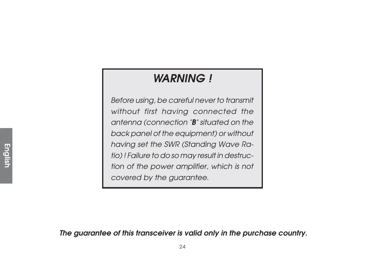
Before using, be careful never to transmit without first having connected the antenna (connection "B" situated on the back panel of the equipment) or without having set the SWR (Standing Wave Ratio)! Failure to do so may result in destruction of the power amplifier, which is not covered by the guarantee.
The guarantee of this transceiver is valid only in the purchase country.
Welcome to the world of the new generation of CB radios. The new PRESIDENT range gives you access to top performance CB equipment. With the use of up-to-date technology, which guarantees unprecedented quality, your PRESIDENT JOHNSON ASC is a new step in personal communications and is the surest choice for the most demanding of professional CB radio users. To ensure that you make the most of all its capacities, we advise you to read carefully this manual before installing and using your PRESIDENT JOHNSON ASC.
A) INSTALLATION:
1) WHERE AND HOW TO MOUNT YOUR MOBILE CB RADIO:
a) You should choose the most appropriate setting from a simple and practical point of view.
b) Your CB radio should not interfere with the driver or the passengers.
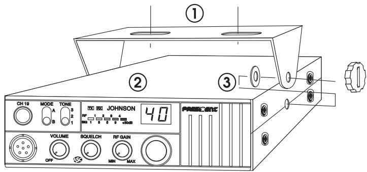
MOUNTING DIAGRAM
c) Remember to provide for the passing and protection of different wires (e.g. power, antenna, accessory cabling) so that they do not in any way interfere with the driving of the vehicle.
d) To install your equipment, use the cradle (1) and the self-tapping screws (2) provided (drilling diameter 3.2mm ). Take care not to damage the vehicle's electrical system while drilling the dash board.
e) Do not forget to insert the rubber joints (3) between the CB and its support as these have a shock-absorbing effect which permits gentle orientation and tightening of the set.
f) Choose where to place the microphone support and remember that the microphone cord must stretch to the driver without interfering with the controls of the vehicle.
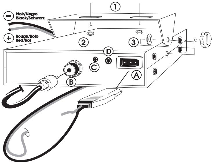
- N.B.: As the transceiver has a frontal microphone socket, it can be set into the dash board. In this case, you will need to add an external loud speaker to improve the sound quality of communications (connector EXT.SP situated on the back panel: D). Ask your dealer for advice on mounting your CB radio.
2) ANTENNA INSTALLATION:
a) Choosing your antenna:
- For CB radios, the longer the antenna, the better its results. Your dealer will be able to help you with your choice of antenna.
b) Mobile antenna:
- Must be fixed to the vehicle where there is a maximum of metallic surface (ground plane), away from windscreen mountings.
- If you already have a radio-telephone antenna installed, the CB antenna should be higher than this.
- There are two types of antenna: pre-regulated which should be used on a good ground plane (e.g. car roof or lid of the boot), and
adjustable which offer a much larger range and can be used on a smaller ground plane (see p 27 § 5, Adjustment of SWR). - For an antenna which must be fixed by drilling, you will need a good contact between the antenna and the ground plane. To obtain this, you should lightly scratch the surface where the screw and tightening star are to be placed.
- Be careful not to pinch or flatten the coaxial cable (as this runs the risk of break down and/or short circuiting).
- Connect the antenna (B).
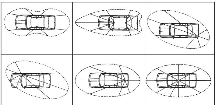
OUTPUT RADIUS PATTERNS
c) Fixed antenna:
- A fixed antenna should be installed in a clear space as possible. If it is fixed to a mast, it will perhaps be necessary to stay it, according to the laws in force (you should seek professional advice). All PRESIDENT antennas and accessories are designed to give maximum efficiency to each CB radio within the range.
3) POWER CONNECTION:
Your PRESIDENT JOHNSON ASC is protected against an inversion of polarities. However, before switching it on, you are advised to check all the connections. Your equipment must be supplied with a continued current of 12 volts (A). Today, most cars and lorries are negative earth. You can check this by making sure that the negative terminal of the battery is connected either to the engine block or to the chassis. If this is not the case, you should consult your dealer.
WARNING: Lorries generally have two batteries and an electrical installation of 24 volts, in which case it will be necessary to insert a 24/12 volt converter (type CV 24/12 PRESIDENT) into the electrical circuit. The following connection steps should be carried out with the power cable disconnected from the set.
a) Check that the battery is of 12 volts.
b) Locate the positive and negative terminals of the battery (+ is red and - is black). Should it be necessary to lengthen the power cable, you should use the same or a superior type of cable.
c) It is necessary to connect your CB to a permanent (+) and (-). We advise you
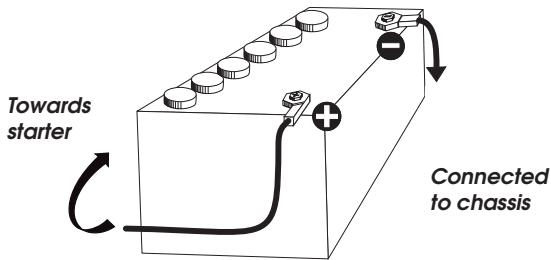
to connect the power cable directly to the battery (as the connection of the CB cable to the wiring of the car-radio or other parts of the electrical circuit may, in somecases, increase the likelihood of interference).
d) Connect the red wire (+) to the positive terminal of the battery and the black (-) wire to the negative terminal of the battery.
e) Connect the power cable to your CB radio.
WARNING: Never replace the original fuse (5A) by one of a different value.
4) BASIC OPERATIONS TO BE CARRIED OUT BEFORE USING YOUR SET FOR THE FIRST TIME (without transmitting and without using the “push-to-talk” switch on the microphone):
a) Connect the microphone
b) Check the antenna connections
c) Turn the set on by turning the knob VOLUME clockwise.
d) Turn the SQUELCH knob to minimum (anti-clockwise). Adjust the volume to a comfortable level.
e) Go to Channel 20 using either the «CH▲» «CH▼» key on the microphone or the rotary knob.
5) ADJUSTMENT OF SWR (Standing wave ratio):
WARNING: This must be carried out when you use your CB radio for the first time (and whenever you re-position your antenna). The adjustment must be carried out in an obstacle-free area.
- Using an external SWR meter (e.g. SWR 1 or SWR 2):
a) To connect the SWR meter : - Connect the SWR meter between the CB radio and the antenna as close as possible to the CB (use a maximum of 40~cm cable, type CA 2C).
b) To adjust the SWR meter:
- Set the CB to channel 20.
- Put the switch on the SWR meter to position CAL ou FWD.
- Press the «push-to-talk» switch on the microphone.
- Bring the index needle to by using the calibration key.
- Change the switch to position SWR (reading of the SWR level). The reading on the V.U. meter should be as near as possible to 1. If this is not the case, re-adjust your antenna to obtain a reading as close as possible to 1. (An SWR reading between 1 and 1.8 is acceptable).
- It will be necessary to re-calibrate the SWR meter after each adjustment of the antenna.
Your CB is now ready for use.
a) To turn the set on, turn the knob (1) clockwise
b) To increase the sound level, turn the same knob further clockwise.
2) ASC (Automatic Squelch Control)/SQUELCH:
Suppresses undesirable back-ground noises when there are no communication. Squelch does not effect neither sound nor transmission power, but allows a considerable improvement in listening comfort.
a) ASC: Automatic Squelch Control Worldwide patent, a PRESIDENT exclusivity
No repetitive manual adjustment and a permanent improvement in listening comfort when this function is active. It can be disconnected by turning the switch (2) clockwise, in this case the manual squelch control becomes active again.
b) Turn the squelch knob clockwise to the exact point where all background noise disappears. This adjustment should be done with precision as, if set to maximum, (i.e. fully clockwise) only the strongest signals will be received.
3) RF GAIN:
This knob is for adjusting sensitivity during reception. For long distance communications RF GAIN should be set to maximum. RF GAIN can be reduced to avoid distortion, when your correspondent is close by and when he does not have RF POWER.
The normal setting of this knob is on maximum (fully clockwise).
4) CHANNEL SELECTOR KEYS «CH▲», «CH▼» AND/OR ROTARY KNOB:
The two keys, «CH▲» and «CH▼» on the microphone and on the front panel, allow you to go up and down the channels. This can also be done using the channel rotary knob.
«CH▼» key: one quick press allows you to go down by one channel, continued press allows you to descend five channels per second.
«CH▲» key: one quick press allows you to go up by one channel, continued pressure allows you to ascend five channels per second.
5) DISPLAY:
The display shows all the different functions. The bargraph shows the level of reception and the level of power emitted.
6) TONE:
This function is used to adjust the tone during reception.
7) MODE:
Use this key to select AM or FM. The modulation mode must correspond with that of the person with whom you communicate.
A/ Amplitude Modulation (AM) is for communications in areas where there are obstacles and over medium distances.
B/ Frequency Modulation (FM) is for nearby communications in flat, open areas. It gives better quality of communication (squelch adjustment needs more finesse).
8) CH 19:
Channel 19 AM is automatically selected when you depress this key. This function is activated by depressing the key. To return to the previous configuration re-depress the same key.
9) 6-PIN MICROPHONE PLUG:
This plug is situated on the front panel, thereby making it easier to set the equipment into the dashboard. See the cabling diagram on page 46.
10) PTT:
Depress this knob to transmit a message and release to listen to an incoming communication.
A) DC-POWER TERMINAL (13,2 V)
B) ANTENNA CONNECTOR (SO-239)
C) EXTERNAL S-METER JACK (Ø 2,5 mm)
D) EXTERNAL SPEAKER JACK (8 Ω, 0 3,5 mm)
C) TECHNICAL CHARACTERISTICS:
1) GENERAL:
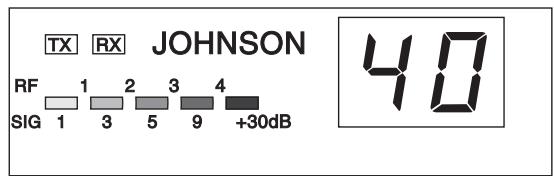
- Channels
- Modulation modes
- Frequency ranges
- Antenna impedance
- Power supply
- Dimensions (in mm)
Weight - Accessories supplied
:40
AM/FM
from 26.965 MHz to 27.405 MHz
: 50 ohms
13.2V
174 (L) x 211 (H) x 52 (D)
1.1kg
UP/DOWN microphone with support, mounting cradle, screws.
2) TRANSMISSION:
Frequency allowance
- Carrier power
Transmission interference
- Audio response
- Emitted power in the adj. channel
- Microphone sensitivity
-Drain
- Modulated signal distortion
+/-300 Hz
4 watts FM
4 watts AM PEP
: inferior to 4 nW (- 54 dBm)
300 Hz à 3 kHz in AM/FM
: inferior to 20~ W
0.8mV
1,7 A (with modulation)
1.8%
3) RECEPTION:
Maxi. sensitivity at 20 dB sinad
Frequency response
- Adjacent channel selectivity
Maximum audio power
Squelch sensitivity
0.4 V - 115 dBm (AM/FM)
300 Hz à 3 kHz in AM/FM
70dB
5W
: minimum 0.2 V - 120 dBm
maximum 1 mV - 47 dBm
60 dB
70dB
500 mA nominal
800 mA maximum
D) BREAKDOWN GUIDE:
1) YOUR CB RADIO WILL NOT TRANSMIT OR YOUR TRANSMISSION IS OF POOR QUALITY:
- Check that the antenna is correctly connected and that the SWR is properly adjusted.
- Check that the microphone is properly plugged in.
- With the «push-to-talk» switch activated, the display flashes. Release the «push-to-talk» switch, then re-press it to go into transmission.
2) YOUR CB RADIO WILL NOT RECEIVE OR RECEPTION IS POOR:
- Check that the squelch level is properly adjusted.
- Check that the volume is set to a comfortable listening level.
- Check that the microphone is properly plugged in.
- Check that the antenna is correctly connected and that the SWR is properly adjusted.
- Check that you are using the same modulation mode as your correspondent.
3) YOUR CB WILL NOT LIGHT UP:
- Check the power supply.
- Check the connection wiring.
- Check the fuse.
E) HOW TO TRANSMIT OR RECEIVE AMESSAGE:
Now that you have read the manual, make sure that your CB Radio is ready for use (i.e. check that your antenna is connected).
Choose your channel (19, 27).
Choose your mode (AM/FM) which must be the same as that of your correspondent.
Press the "push-to-talk" switch and announce your message "Attention stations, transmission testing" which will allow you to check the cleanness and the power of your signal. Release the switch and wait for a reply. You should receive a reply like, "Strong and clear".
If you use a calling channel (19, 27) and you have established communication with someone, it is common practice to choose another available channel so as not to block the calling channel.
F) GLOSSARY:
Below you will find some of the most frequently used CB radio expressions. Remember this is meant for fun and that you are by no means obliged to use them. In an emergency, you should be as clear as possible.
INTERNATIONAL PHONETIC ALPHABET:
A Alpha
B Bravo
C Charlie
D Delta
E Echo
F Foxtrott
G Golf
H Hotel
I India
J Juliett
L Lima
M Mike
N November
Oscar
P Papa
Q Quebec
R Romeo
Sierra
T Tango
U Uniform
V Victor
W Whiskey
YYankee
Z Zulu
TECHNICAL VOCABULARY:
AM Amplitude Modulation
CB : Citizen's Band
CH Channel
CW : Continuous Wave
DX : Long Distance Liaison
DW
FM
GMT
HF
LF
LSB
RX
SSB
SWR
SWL
SW
TX
UHF
USB
VHF
Dual Watch
Frequency Modulation
: Greenwich Meantime
High Frequency
Low Frequency
Lower Side Band
: Receiver
: Single Side Band
Standing Wave Ratio
Short Wave Listening
Short Wave
CB Transceiver
: Ultra High Frequency
Upper Side Band
: Very High Frequency
CB LANGUAGE:
Advertising
Back off
Basement
Base station
Bear
Bear bite
Bear cage
Big slab
Big 10-4
Bleeding
Blocking the channel
Blue boys
Break
Breaker
Clean and green
Cleaner channel
Coming in loud and proud
Doughnut
Down and gone
Down one
Do you copy?
: Flashing lights of police car
: Slow down
: Channel 1
A CB set in fixed location
Policeman
: Speeding fine
Police station
Motorway
: Absolutely
Signal from an adjacent channel interfering with the transmission
: Pressing the PTT switch without talking : Police
Used to ask permission to join a conversation
A CBer wishing to join a channel Clear of police
: Channel with less interference
Good reception
: Tyre
: Turning CB off
: Go to a lower channel
: Understand?
| DX | : | Long distance |
| Eighty eights | : | Love and kisses |
| Eye ball | : | CBers meeting together |
| Good buddy | : | Fellow CBer |
| Hammer | : | Accelerator |
| Handle | : | CBer's nickname |
| Harvey wall banger | : | Dangerous driver |
| How am I hitting you? | : | How are you receiving me? |
| Keying the mike | : | Pressing the PIT switch without talkin |
| Kojac with a kodak | : | Police radar |
| Land line | : | Telephone |
| Lunch box | : | CB set |
| Man with a gun | : | Police radar |
| Mayday | : | SOS |
| Meat wagon | : | Ambulance |
| Midnight shopper | : | Thief |
| Modulation | : | Conversation |
| Negative copy | : | No reply |
| Over your shoulder | : | Right behind you |
| Part your hair | : | Behave yourself - police ahead |
| Pull your hammer back | : | Slow down |
| Rat race | : | Congested traffic |
| Rubberbander | : | New CBer |
| Sail boat fuel | : | Wind |
| Smokey dozing | : | Parked police car |
| Smokey with a camera | : | Police radar |
| Spaghetti bowl | : | Interchange |
| Stinger | : | Antenna |
| Turkey | : | Dumb CBer |
| Up one | : | Go up one channel |
| Wall to wall | : | All over/everywhere |
| What am I putting to you? | : | Please give me an S-meter reading. |
ACHTUNG!
H Hotel
I India
J Juliett
L Lima
M Mike
N November
Oscar
P Papa
Q Quebec
R Romeo
Sierra
Tango
U Uniform
V Victor
W Whiskey
YYankee
Z Zulu
R/S-Code:
R = Lesbarkeit
Emisora CB President JOHNSON
Name and title of subscriber :
GPE, ALBERT BERTRANA, Director Tecnico
P/O Michel FABRI
Place, date and signature :
Modèle JOHNSON FM

APPAREIL CONFORME A LA NORME EUROPEENNE
ETS 300 135 : 40 CANAUX, 4 W FM
AGREMENT DGPT N° 95 0297 CB 0
Addition to the service manual supplied
PAGE 28:
7) The function key MODE (7) doesn't function. Your transceiver is only functioning in FM mode.
8) The function key CH 19 (8) activates only the CH 19 FM.
PAGE 29:
D) TECHNICAL SPECIFICATIONS :
1) GENERAL:
- Channels 40
- Modulation modes FM
2) TRANSMISSION: