
NINJA - Radio transceiver PRESIDENT - Free user manual and instructions
Find the device manual for free NINJA PRESIDENT in PDF.



User questions about NINJA PRESIDENT
0 question about this device. Answer the ones you know or ask your own.
Ask a new question about this device
Download the instructions for your Radio transceiver in PDF format for free! Find your manual NINJA - PRESIDENT and take your electronic device back in hand. On this page are published all the documents necessary for the use of your device. NINJA by PRESIDENT.
USER MANUAL NINJA PRESIDENT
1) MARCHE/ARRET - VOLUME
LCR (Last Channel Recall)
H Hotel
I India
J Juliett
L Lima
M Mike
N November
Oscar
P Papa
Q Quebec
R Romeo
Sierra
T Tango
U Uniform
V Victor
W Whiskey
YYankee
Z Zulu
LANGUAGE TECHNIQUE :
27 AM
19 AM
9 AM
11 FM
LCR (Last Channel Recall)
H Hotel
I India
J Juliett
L Lima
M Mike
N November
Oscar
P Papa
Q Quebec
R Romeo
Sierra
Tango
U Uniform
V Victor
W Whiskey
YYankee
Z Zulu
TERMINOS DEL ARGOT CEBEISTA:
A.L.
ARMONICOS
AVE MARIA
BARBAS
BARRA MOVIL
BASE
BIGOTADA
BREAK
BREAKER
CAJATONTA
CHICHARRA
CORTINERO
CRUCE DE ANTENAS
DOS METROS HORIZONTALES :
ENCENDER FILAMENTOS
ESPIRAS
FOTOCOPIA
FRECUENCIA
KAS
LABORO
LADRILLO
Amplificador lineal
Hijos
Jean Gilbert Muller
Director General
CONDICIONES GENERALES DE GARANTÍA EN ESPaña
PARTE A CONSERVAR
PRESIDENT
ANTENAS TBERICA
Botanica, 107-109, Pol. Ind. Gran Via Sud 08908 L'HOSPITALET DE LLOBREGAT BARCELONA
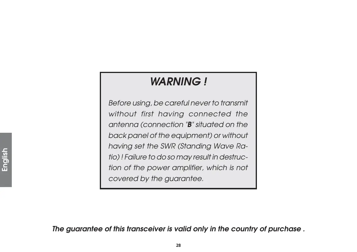
Before using, be careful never to transmit without first having connected the antenna (connection "B" situated on the back panel of the equipment) or without having set the SWR (Standing Wave Ratio)! Failure to do so may result in destruction of the power amplifier, which is not covered by the guarantee.
The guarantee of this transceiver is valid only in the country of purchase .
Welcome to the world of the new generation of CB radios. The new EMPEROR range gives you access to top performance CB equipment. With the use of up-to-date technology, which guarantees unprecedented quality, your EMPEROR NINJA is a new step in personal communication and is the surest choice for the most demanding of professional CB radio users. To ensure that you make the most of all its capacities, we advise you to read carefully this manual before installing and using your EMPEROR NINJA.
A) INSTALLATION
1) WHERE AND HOW TO MOUNT YOUR MOBILE CB RADIO
a) You should choose the most appropriate setting from a simple and practical point of view.
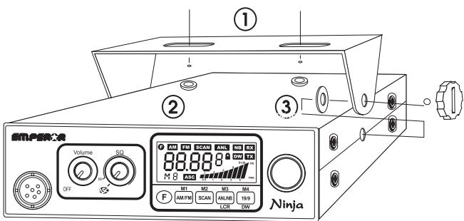
MOUNTING DIAGRAM
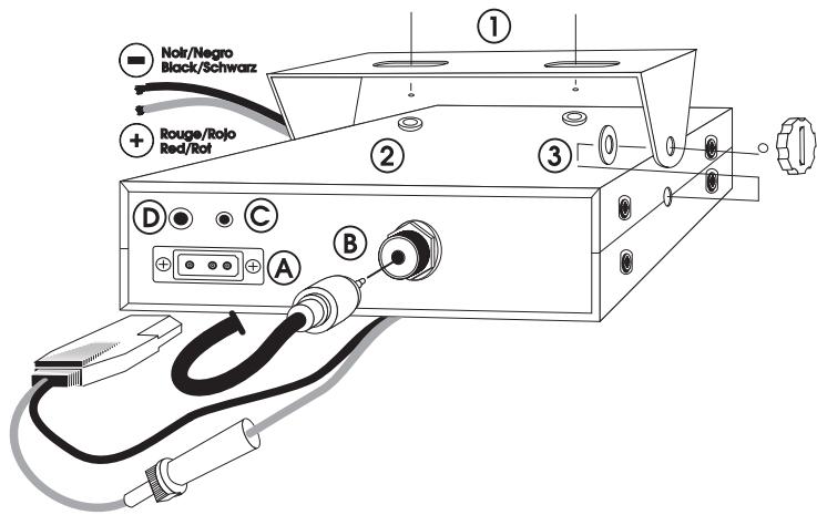
b) Your CB radio should not interfere with the driver or the passengers.
c) Remember to provide for the passing and protection of different wires (e.g. power, antenna, accessory cabling) so that they do not in any way interfere with the driving of the vehicle.
d) To install your equipment, use the cradle (1) and the self-tapping screws (2) provided (drilling diameter 3.2mm ). Take care not to damage the vehicle's electrical system while drilling the dash board.
f) Choose where to place the microphone support and remember that the microphone cord must stretch to the driver without interfering with the controls of the vehicle.
- N.B.: As the transceiver has a frontal microphone socket, it can be set into the dash board. In this case, you will need to add an external loud speaker to improve the sound quality of communications (connector EXT.SP situated on the back panel: D). Ask your dealer for advice on mounting your CB radio.
2) ANTENNA INSTALLATION
a) Choosing your antenna:
- For CB radios, the longer the antenna, the better its results. Your dealer will be able to help you with your choice of antenna.
b) Mobile antenna:
- Must be fixed to the vehicle where there is a maximum of metallic surface (ground plane), away from windscreen mountings.
- If you already have a radio-telephone antenna installed, the CB antenna should be higher than this.
- There are two types of antenna: pre-regulated which should be used on a good ground plane (e.g. car roof or lid of the boot), and
adjustable which offer a much larger range and can be used on a smaller ground plane (see § 5, Adjustment of SWR). - For an antenna which must be fixed by drilling, you will need a good contact between the antenna and the ground plane. To obtain this, you should lightly scratch the surface where the screw and tightening star are to be placed.
- Be careful not to pinch or flatten the coaxial cable (as this runs the risk of break down and/or short circuiting).
- Connect the antenna (B).
c) Fixed antenna:
- A fixed antenna should be installed in a clear space as possible. If it is fixed to a mast, it will perhaps be necessary to stay it, according to the laws in force (you should seek professional advice). All PRESIDENT antennas and accessories are designed to give maximum efficiency to each CB radio within the range.
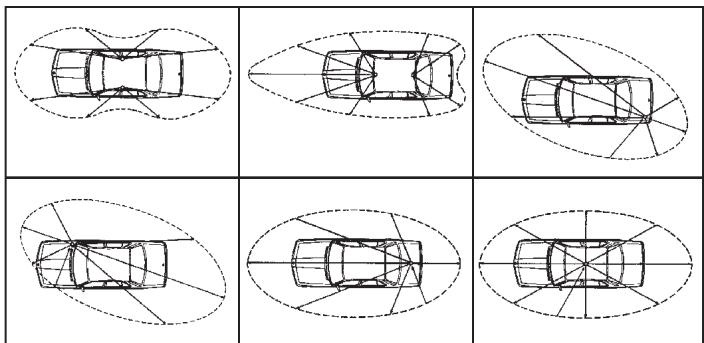
OUTPUT RADIUS PATTERNS
3) POWER CONNECTION
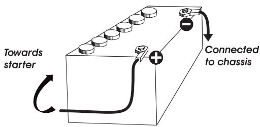
Your EMPEROR NINJA is protected against an inversion of polarities. However, before switching it on, you are advised to check all the connections. Your equipment must be supplied with a continued current of 12 volts (A). Today, most cars and lorries are negative earth. You can check this by making sure that the negative terminal of the battery is connected either to the engine block or to the chassis. If this is not the case, you should consult your dealer.
WARNING: Lorries generally have two batteries and an electrical installation of 24 volts, in which case it will be necessary to insert a 24/12 volt converter (type CV24/12 PRESIDENT) into the electrical circuit. The following connection steps should be carried out with the power cable disconnected from the set.
a) Check that the battery is of 12 volts.
b) Locate the positive and negative terminals of the battery (+ is red and - is black). Should it be necessary to lengthen the power cable, you should use the same or a superior type of cable.
c) It is necessary to connect your CB to a permanent (+) and (-). We advise you to connect the power cable directly to the battery (as the connection of the CB cable to the wiring of the car-radio or other parts of the electrical circuit may, in some cases, increase the likelihood of interference).
d) Connect the red wire (+) to the positive terminal of the battery and the black (-) wire to the negative terminal of the battery.
e) Connect the power cable to your CB radio.
WARNING: Never replace the original fuse (2 A) by one of a different value.
4) BASIC OPERATIONS TO BE CARRIED OUT BEFORE USING YOUR SET FOR THE FIRST TIME (without transmitting and without using the “push-to-falk” switch on the microphone)
a) Connect the microphone
b) Check the antenna connections
c) Turn the set on by turning the knob VOLUME (1) clockwise.
d) Turn the SQUEELCH knob to minimum (anti-clockwise).
e) Adjust the volume to a comfortable level.
f) Go to Channel 20 using the rotary knob on the front panel or UP / DOWN button on microphone (4).
5) ADJUSTMENT OF SWR (Standing wave ratio)
WARNING: This must be carried out when you use your CB radio for the first time (and whenever you re-position your antenna). The adjustment must be carried out in an obstacle-free area.
- Using an external SWR meter (e.g. SWR 1 or SWR 2):
a) To connect the SWR meter :
- Connect the SWR meter between the CB radio and the antenna as close as possible to the CB (use a maximum of 40~cm cable, type President CA 2C).
b) To adjust the SWR meter:
- Set the CB to channel 20.
- Put the switch on the SWR meter to position CAL ou FWD.
- Press the "push-to-talk" switch on the microphone to transmit.
- Bring the index needle to by using the calibration key.
- Change the switch to position SWR (reading of the SWR level). The reading on the V.U. meter should be as near as possible to 1. If this is not the case, re-adjust your antenna to obtain a reading as close as possible to 1. (An SWR reading between 1 and 1.8 is acceptable).
- It will be necessary to re-calibrate the SWR meter after each adjustment of the antenna.
Your CB is now ready for use.
a) To turn the set on, turn the knob (1) clockwise
b) To increase the sound level, turn the same knob further clockwise.
2) ASC (Automatic Squelch Control)/SQUEELCH
Suppresses undesirable back-ground noises when there are no communication. Squelch does not effect neither sound nor transmission power, but allows a considerable improvement in listening comfort.
a) ASC: Automatic Squelch Control Worldwide patent, a PRESIDENT exclusivity
No repetitive manual adjustment and a permanent improvement in listening comfort when this function is active. It can be disconnected by turning the switch (2) clockwise, in this case the manual squelch control becomes active again.
b) Turn the squelch knob clockwise to the exact point where all back-ground noise disappears. This adjustment should be done with precision as, if set to maximum, (i.e. fully clockwise) only the strongest signals will be received.
3) DISPLAY
Multifunction LCD display (with back-light). The display shows all the different functions.
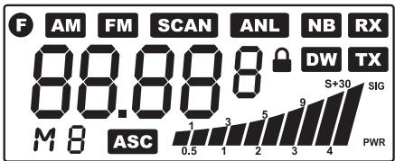
F
AM
FM
SCAN
ANL

NB
DW
RX
88.88
M
ASC

TX
FUNCTION activated
AM mode
FM mode
SCAN mode
ANL mode
LOCK : key lock enabled
NB mode
DW : dual watch activated
RX: receipt mode
channel number or channel frequency or frequency band
preset memory channels
ASC mode
the received signal strength and the power of the transmitting signal
transmission mode
4) CHANNEL SELECTOR: ROTARY KNOB, UP and DOWN button on microphone
Turning this knob allows you to choose a channel for transmitting and receiving.
Buttons on microphone allows you to choose the next (UP) or the previous (DOWN) channel. A beep is heard every time the channel is changed.6)
This plug is situated on the front panel, thereby making it easier to set the equipment into the dashboard.
See the cabling diagram on page 48.
6) F BUTTON
Function Button.
Allows you to select a CHANNEL NUMBER or CHANNEL FREQUENCY DISPLAY via the LCD display.
Press the F key during approximately 2 seconds, you may then select either frequency display or channel number.
Example : Channel 40 on the EU band : EU 40 or 27.405 MHz.
With this control, you can automatically seek a busy channel.
9) ANL/NB selector ~ M3 and LCR
Noise Blanker/ Automatic Noise Limiter. These filters allow the reduction of back ground noise, and some reception interference.
AM Mode (NB and ANL active)
Press this key once to activate the NB filter. NB appears in the display. A second depression of the same key activates ANL. ANL appears in the display. A third depression of the same key activates both NB and ANL. NB ANL appears in the display. A fourth depression cancels both filters and NB ANL disappears from the display.
FM Mode (NB only)
To activate the NB filter, press the key once. NB appears in the display. To cancel, depress the same key. NB disappears from the display.
LCR
Last channel recall.
10) 19 / 9 M4 and DW
EMG channel selector : to select channel 19 or channel 9.
DW (DUAL WATCH)
To activate DUAL WATCH, proceed as follows :
- Select the required channel through the channel selector or the UP / DOWN buttons on the microphone.
- Press the DW button during about 2 seconds: you will hear a « beep » and DW will flash on the display.
- Select the second channel with the same procedure.
- Press the DW button again during approx. 2 seconds: you will hear a « BEEP »; the display will permanently show DW and will alternatively display the two selected channels; the radio will start its dual watch monitoring.
CHANNEL MEMORY ~ M1/M2/M3/M4
The CB can store and recall, when necessary, 4 channels previously stored in the memory.
To store or recall a channel into the memory, use the following procedure.
- Select the channel with the appropriate control or the UP / DOWN buttons on the microphone.
- Push the F button : the display will show F.
- Press and release M1 button for recall memory channel.
- Press and hold the M1 button during 2 seconds. The unit will store a new memory, you will hear a « BEEP » and the display will show M1.
11)Lock button
it allows you to lock / unlock the key buttons.
12)PTT (push to talk):
Depress this knob to transmit a message and release to listen to an incoming communication.
A) DC-POWER TERMINAL (13,2 V)
B) ANTENNA CONNECTOR (SO-239)
C) EXTERNAL S-METER JACK (Ø 2,5 mm)
D) EXTERNAL SPEAKER JACK (8 Ω, Ø 3,5 mm)
The frequency bands must be chosen according to the country where you are going to operate. Do not use another configuration. Some countries require user's licence.
Procedure :
- Switch off the unit.
- Turn it on while pushing the F and 19/9 buttons at the same time.
- Rotate the Channel knob and select the desired frequency band (See the
chart here below)
- To stop your selection, press the F button.
NOTE : In the EU/UK , you can select directly the EU or UK band by pushing the AM/FM button.
| Digits displayed | Country |
| I | Italy 40 CH AM/FM 4 Watt |
| I2 | Italy 34 CH AM/FM 4 Watt |
| D | Germany 80 CH FM 4 Watt/ 80 CH AM 1 Watt |
| D2 | Germany 40 CH FM 4 Watt/ 40 CH AM 1 Watt |
| EU | Europe 40 CH FM 4 Watt/ 40 CH AM 1 Watt |
| EC | CEPT 40 CH FM 4 Watt |
| E | Spain 40 CH AM/FM 4 Watt |
| F | France 40 CH FM 4 Watt / 40 CH AM 1 Watt |
| PL | Poland 40 CH AM/FM 4 Watt |
| UK | England 40 CH FM 4 Watt English frequencies |
| EU/UK | Europe 40 CH FM 4 Watt + England 40 CH FM 4 Watt |
C) TECHNICAL CHARACTERISTICS
1) GENERAL
- Channels
(according to the selected band)
- Frequency range
- Frequencies
- Operating Temperature Range
- DC input voltage
-Size - Weight
: 80 channels
: 26.565 to 27.405 MHz
:PLL
: -10°C / +55°C
13.2 V DC ±15%
: 150 (L) x 200 (H) x 45 (D) mm
: 1.050 kg
2) RECEIVER
Receiving system
- Intermediate Frequency
- Sensitivity
- Audio Distortion
- Image rejection
- Adjacent Channel rejection
- Signal/Noise Ratio
- Current drain at Standby
: Dual Conversion Super hétérODYne
: 1^ IF :10.695 MHz, 2^ IF : 455 MHz
: 0.5 μV for 20 dB SINAD in AM / FM
: less than 8% @ 1 KHz
: 65 dB
: 65 dB
:45dB
: 325 mA
3) TRANSMITTER
- Output power
- Modulation
- Frequency response
- Output impedance
- Signal/Noise Ratio
-Current Drain
: 4W@ 13.2 V DC
: FM : 1.8 KHz ± 0.2 KHz
: from 400 Hz to 2.5 KHz
: RF 50 Ohms
: 40 dB MIN
: 1300 mA
D) TROUBLE SHOOTING
1) YOUR CB RADIO WILL NOT TRANSMIT OR YOUR TRANSMISSION IS OF POOR QUALITY:
- Check that the antenna is correctly connected and that the SWR is properly adjusted.
- Check that the microphone is properly plugged in.
2) YOUR CB RADIO WILL NOT RECEIVE OR RECEPTION IS POOR:
- Check that the squelch level is properly adjusted.
- Check that the volume is set to a comfortable listening level.
- Check that the microphone is properly plugged in.
- Check that the antenna is correctly connected and that the SWR is properly adjusted.
- Check that you are using the same modulation mode as your correspondent.
3) YOUR CB WILL NOT LIGHT UP:
- Check the power supply.
- Check the connection wiring.
- Check the fuse.
E) HOW TO TRANSMIT OR RECEIVE AMESSAGE:
Now that you have read the manual, make sure that your CB Radio is ready for use (i.e. check that your antenna is connected).
Choose your channel (19, 27).
Choose your mode (AM/FM) which must be the same as that of your correspondent.
Press the "push-to-talk" switch and announce your message "Attention stations, transmission testing" which will allow you to check the cleanness and the power of your signal. Release the switch and wait for a reply. You should receive a reply like, «Strong and clear».
If you use a calling channel (19, 27) and you have established communication with someone, it is common practice to choose another available channel so as not to block the calling channel.
F) GLOSSARY:
Below you will find some of the most frequently used CB radio expressions. Remember this is meant for fun and that you are by no means obliged to use them. In an emergency, you should be as clear as possible.
INTERNATIONAL PHONETIC ALPHABET:
A Alpha
B Bravo
C Charlie
D Delta
E Echo
F Foxtrott
G Golf
H Hotel
I India
J Juliett
L Lima
M Mike
N November
Oscar
P Papa
Q Quebec
R Romeo
Sierra
T Tango
U Uniform
V Victor
W Whiskey
YYankee
Z Zulu
TECHNICAL VOCABULARY:
DW : Dual Watch
FM Frequency M
GMT : Greenwich Meantime
HF : High Frequency
LF Low Frequency
LSB : Lower Side Band
RX Receiver
SSB : Single Side Band
SWR Standing Wave Ratio
SWL : Short Wave Listening
SW : Short Wave
TX : CB Transceiver
UHF Ultra High Frequency
USB Upper Side Band
VHF Very High Frequency
CB LANGUAGE:
Advertising
Back off
Basement
Base station
Bear
Bear bite
Bear cage
Big slab
Flashing lights of police car
Slow down
Channel 1
A CB set in fixed location
Policeman
Speeding fine
Police station
Motorway
Big 10-4
Bleeding
Blocking the channel
Blue boys
Break
Breaker
Clean and green
Cleaner channel
Coming in loud and proud:
Doughnut
Down and gone
Down one
Do you copy?
DX
Eighty eights
Eye ball
Good buddy
Hammer
Handle
Harvey wall banger
How am I hitting you?
Keying the mike
Kojac with a kodak
Land line
Lunch box
Man with a gun
Mayday
Meat wagon
Midnight shopper
Modulation
Negative copy
Over your shoulder
Part your hair
Pull your hammer back
Rat race
Rubberbander
Sail boat fuel
Smokey dozing
Smokey with a camera
Spaghetti bowl
Stinger
Turkey
Up one
Wall to wall
What am I putting to you? :
Absolutely
Signal from an adjacent channel
interfering with the transmission
Pressing the PTT switch without talking
Police
Used to ask permission to join a conversation
A CBer wishing to join a channel
Clear of police
Channel with less interference
Good reception
Tyre
Turning CB off
Go to a lower channel
Understand?
Long distance
Love and kisses
CBers meeting together
Fellow CBer
Accelerator
CBer's nickname
Dangerous driver
How are you receiving me?
Pressing the PTT switch without talking
Police radar
Telephone
CB set
Police radar
SOS
Ambulance
Thief
Conversation
No reply
Right behind you
Behave yourself - police ahead
Slow down
Congested traffic
New CBer
Wind
Parked police car
Police radar
Interchange
Antenna
Dumb CBer
Go up one channel
All over/everywhere
Please give me an S-meter reading.
CERTIFICATE OF CONFORMITY
We, GROUPE PRESIDENT ELECTRONICS, Route de Sète, BP 100-34540 Balaruc-FRANCE,
Declare, on our own responsibility that the CB radio-communication transceiver
Brand : EMPEROR
Model:NINJA
Manufactured in Thailand
is in conformity with the essential requirements of the Directive 1999/5/CE (Article 3) adapted to the national law, as well as with the following European Standards:
EN 300 135-2:v1.1.1 (2000)
EN 300 433-2 :v1.1.2 (2000)
EN 301 489-13 v 1.2.1 (2002)
EN 60215 (1996)
Balaruc, the 2003-12-10
Jean-Gilbert MULLER
General Manager
ACHTUNG!
LCR (Last Channel Recall)
Sendetaste (Push-to-Talk).
A) 13,8VDC
: 26.565 to 27.405 MHz
Countries in which there are particular restrictions
Countries in which the national regulations authorize a transmission power superior to the limit fixed by the harmonised standard, notified in the 4th paragraph of the preface of the proper harmonised standard EN 300 433.