
CS 800S - Power amplifier PEAVEY - Free user manual and instructions
Find the device manual for free CS 800S PEAVEY in PDF.
User questions about CS 800S PEAVEY
0 question about this device. Answer the ones you know or ask your own.
Ask a new question about this device
Download the instructions for your Power amplifier in PDF format for free! Find your manual CS 800S - PEAVEY and take your electronic device back in hand. On this page are published all the documents necessary for the use of your device. CS 800S by PEAVEY.
USER MANUAL CS 800S PEAVEY
| A Intended to alert the user to the presence of uninsulated "dangerous voltage" within the product's enclosure that may be of sufficient magnitude to constitute a risk of electric shock to persons. A Intended to alert the user of the presence of important operating and maintenance (servicing) instructions in the literature accompanying the product. CAUTION: Risk of electrical shock – DONOT OPEN! CAUTION: To reduce the risk of electric shock, do not remove cover. No user serviceable parts inside. Refer servicing to qualified service personnel. |
| WARNING: To prevent electrical shock or fire hazard, do not expose this appliance to rain or moisture. Before using this appliance, read the operating guide for further warnings. |
Congratulations on your purchase of the new CS® 800S stereo power amplifier. This latest version is the most advanced ever, using state-of-the-art switching power supply technology to deliver high fidelity and rock solid performance in a two-rack-space unit that weighs just under 23 pounds. This new design retains the extended performance capability of the old CS® 800X, providing impressive two ohm output power capability, and maintaining the old 4 & 8 ohms ratings with awesome industry standards for power bandwidth, slew rate and distortion specifications. The new "S" design also reflects a significant improvement in damping factor specifications. Following is the new CS 800S specs:
- 420 W RMS into 4 ohms...600 W RMS into 2 ohms (per channel)
840 W RMS into 8 ohms... 1200 W RMS into 4 ohms (bridged) - DDT™ compression with LED indicators and defeat switch
- Slew Rate: 40 V/microsecond, stereo mode, each channel
- Power Bandwidth: 10 Hz to 50 KHz @ 4 ohms, @ rated power
Total Harmonic Distortion: Less than 0.03% ,@ rated power - Hum and Noise: 100 dB below rated power, unweighted
- Damping Factor: Greater than 7000 @ 4 ohms, 100 Hz, each channel
The heavy transformer is replaced by an extremely reliable switching power supply that uses proven half-bridge topology to provide 1,700 watts peak power from a high-efficiency IGBT design. The supply has a thermal monitor system with proportional fold-back which prevents a total shut-down at extreme operating temperatures. The new CS800S retains the Peavey patented DDT™ compression system which virtually eliminates any possibility of clipping. The new back panel design now includes plug-in modules for both inputs and outputs offering flexible patching features and various connector choices. Two variable speed DC fans provide tremendous cooling capability upon demand.
THE AMP FEATURES
- Two rack space height-less than 17^ depth
Under 23 lbs...switching power supply - Plug-in modular inputs
- Dual XLR (bal)/phone jack(unbal) with "thru" output per channel
- Universal three-way crossover module
- Plug-in modular outputs
- Dual phone jack and 5-way binding post per channel
- Dual SPEAKON® Quick Connect with patchable selection of pin-outs
- Modular construction
- Replaceable channel and power supply modules
Significant/y reduced mains turn-on surge - Two variable speed DC fans...lower noise levels
- Calibrated/detented input attenuator control each channel
- DDT activation LED & power LED each channel
- Recessed rear panel DDT & bridge switch
- /EC mains connector
THE DIGITAL POWER SUPPLY
- Ultra reliable - Robust
Uses proven Ha/f-Bridge topology-fewer parts
1,700 W peak power...25% over-design
IGBT design...high efficiency
Light weight-cost effective - Massive aluminum heat sink...greater thermal stability
Thermal monitor system with fold-back feature-no shut-down except fault - Effective, low-cost filter design...low conducted EM/
- Fully operational down to 85 V AC Mains (Domestic)... 170 V AC Mains (Export)
We hope you will find your new CS800S not to be just another power amplifier, but the most exciting power amplifier you have ever purchased. Please read over this owners manual carefully. It will help you to use this exciting product most effectively.

FRONT PANEL
DDT™ ACTIVE LED (1)
Illuminates when DDT™ Compression is taking place. With the ENABLE/DEFEAT switch in the DEFEAT position, the LED indicates when clipping distortion is occurring.
POWER LED (2)
Illuminates when AC power is being supplied to the amp and the associated channel is operational. Illumination is delayed slightly during the power-up cycle due to the transient suppression/thermal fault circuitry. If either channel experiences fault conditions or exceeds the safe operating temperature limits, then that channel will shut down, and the associated power LED will go out indicating such conditions exist. Also, whenever the BRIDGE mode is selected, the power LED on channel B is defeated (OFF), just as if there were a fault condition on channel B. This provides a positive indication that the CS 800S is in bridge mode.
INPUT SENSITIVITY (3)
Maximum power amplifier input gain (minimum sensitivity) is achieved at the full clockwise setting. This setting yields maximum mixer/system headroom. A setting of less than full clockwise will yield lower system noise at the expense of headroom. Calibration indicates sensitivity in dBV necessary to attain the full output power rating.
POWER SWITCH (4)
Depress to "on" position to power up unit.
AIR EXHAUST PORT (5)
This is where the hot air from the heat sinks exhaust from the amplifier. Any restriction or blockage could cause excessive operation temperatures and the unit could shut down!
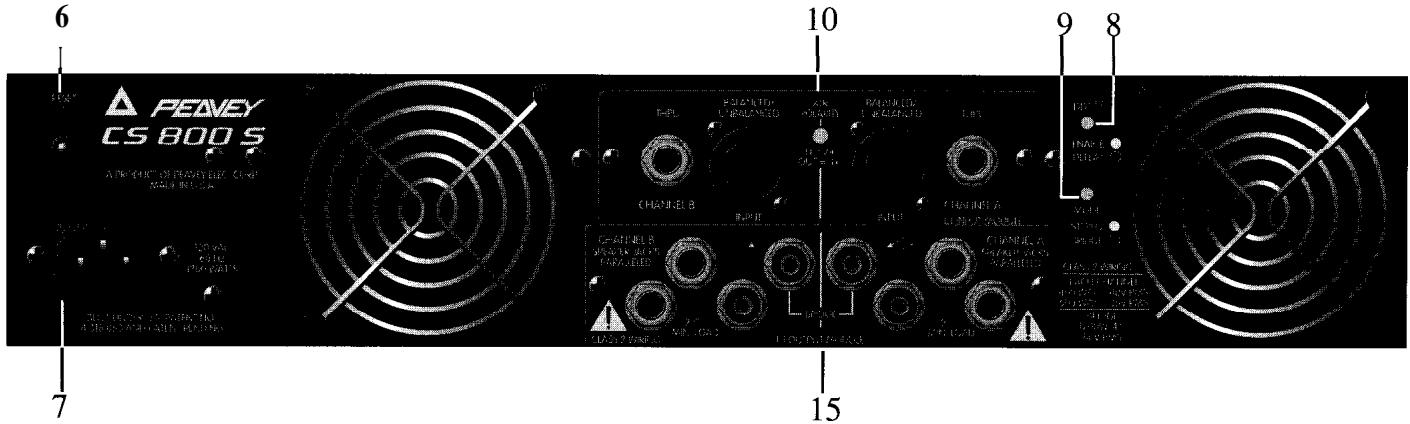
REAR PANEL
CIRCUIT BREAKER (6)
The CS® 800S uses a circuit breaker in place of the main fuse. This breaker is provided to limit the current to the digital power supply and thereby protect it from overheating and possible destruction due to fault conditions in the amplifier. The trip current value has been carefully chosen to allow continuous power output performance while still providing adequate protection for the power supply. Normally this breaker should not trip unless there is a fault in the amplifier circuitry that draws excessive mains current. However, abnormal conditions such as a short circuit on either or both channels or continuous operation at overload or clipping, especially into 2 ohm load will cause the breaker to trip. If this occurs, simply reset the breaker and correct the cause of the overload. When tripped, the button on the breaker will be outward nearly 1/2" , and can be reset by pushing inward. A normal reset button length is about 1/4" . If this "thermal" type breaker does trip, then simply pushing the button back in will reset it after waiting a brief period of time to allow it to cool. If the breaker trips instantly when you attempt to reset it, the unit should be taken to a qualified service center for repair.
The CS 800S is fitted with a universal IEC connector. Into this connector one should always insert a heavy duty #14 AWG 3 conductor line cord with a conventional AC plug with a ground pin. This line cord should be connected to an independent mains circuit capable of supporting at least 15 amps continuously or greater. This is particularly critical for sustained high power applications. If the socket used does not have a ground pin, a suitable ground lift adapter should be used and the third wire grounded properly. Never break off the ground pin on the 3 conductor line cord. The use of extension cords should be avoided, but if necessary, always use a three-wire type with at least a #14 AWG wire size. The use of lighter wire will severely limit the power capability of this amplifier. Always use a qualified electrician to install any necessary electrical equipment. To prevent the risk of shock or fire hazard, always be sure that the amplifier is properly grounded.
DDT™ SWITCH (8)
This switch is used to either ENABLE or DEFEAT the DDT™ compressor.
MODE SWITCH (9)
This switch is used to select either STEREO or BRIDGE mode of operation.
THE B1 INPUT MODULE (10)
The standard input module shipped with each amplifier is called the B1 MODULE. It offers both XLR electronic balanced and phone jack quasi-balanced inputs for each channel using Neutrik's new "combo" connector to save panel space.
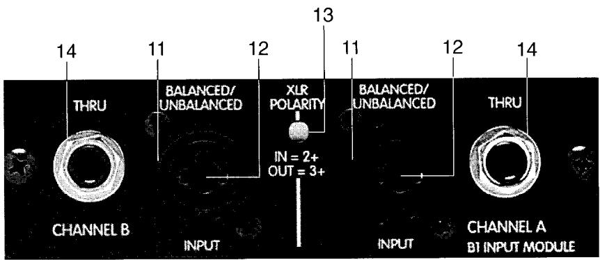
The female XLR inputs (11)
are connected to dual OP AMP circuitry which offers very low noise and extremely high common mode rejection ratio to minimize outside interference!
Between the two XLR connectors is a recessed switch (13) which allows the user to select the desired polarity (phase) of the XLR inputs. This switch is a push-push type and a small diameter "tool" is required to select the desired position. Set to the out (default) position, the polarity is pin #3 positive, pin #2 negative, and pin #1 ground. This is the polarity found on most Peavey power amplifiers. Although this is not the world "standard" (IEC) polarity, it was chosen by Peavey more than 20 years ago, and thus we offer this polarity to be consistent with products both past and present. If this amplifier is used with other competitive products which use the IEC standard polarity, then the "in" position of switch (13) should be selected yielding pin #2 positive, pin #3 negative, and pin #1 ground. As with any electronic gear, polarity (phasing) is important because the loudspeaker enclosures associated with this power amplifier must be in phase with any other loudspeaker enclosures associated with other power amps. If one loudspeaker system were to "push" while the other "pulls", then a serious sound "cancellation" could result. Changing the setting of the polarity switch has the same effect as reversing the polarity of the loudspeaker connections at the output.
The female 1/4" phone jack input (12) in the center of the "comb" connectors are also connected to a unique "quasi-balanced" input circuitry. When used, these 1/4" jacks are not "chassis grounded" but connected to ground through a relatively low impedance circuit which is part of a "ground loop" elimination circuitry associated with the input. This feature will normally allow "hum free" operation when relatively short 1/4" cable patches are made to this input from various outputs on this amp and other equipment that share the same rack with this amp. This "quasi-balanced" circuit is "automatic", and is virtually invisible in normal usage. It can not be defeated.
Each channel also has a female phone jack (14) labeled "thru". This jack offers a very flexible patching capability. When the XLR input connectors (11) are used, then this "thru" jack is the output of the electronic balanced input circuitry, and as such can be used as a "line out" to connect to the other input jack on this amplifier or other amps in the same rack. Thus one balanced mixer feed can be connected to the amp via the XLR connector and then further distributed locally via the "thru" jack. Alternatively, when the 1/4" phone jack input (12) is used as the input, then the "thru" jack becomes a "bridged" input to it (similar to a Y-cord), again allowing this input signal to be patched to the other input jack on this amplifier or other amps in the system.
Additional input modules are available from your authorized Peavey Dealer. Details of these modules and the installation instructions can be secured from this source.
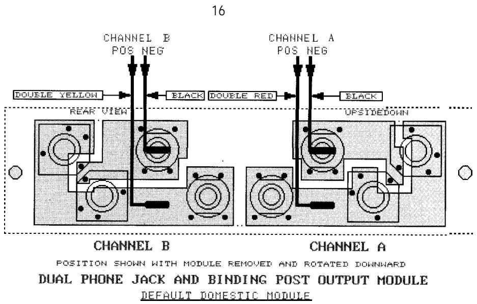
THE P1 OUTPUT MODULE (15)
The standard output module shipped with each amplifier is called the P1 MODULE. It offers both dual 1/4" jacks and 5-way binding post speaker outputs for each channel. For each channel, the outputs are in parallel, hence the speaker connection cables can be
terminated with 1 / 4" phone plugs, or banana plugs or stripped wires for use in the binding post terminals. For sustained high power applications, the use of the binding post terminals are recommended; however, care must be exercised to assure the correct speaker phasing. The red binding posts are the signal outputs from each channel, and the black binding posts are chassis ground. The red binding post should be connected to the positive inputs of the associated loudspeakers. For bridge mode operation, only the red binding posts are used, and the associated loudspeaker load is connected between the two red binding posts. The red binding post associated with channel A should be considered the positive output for the system and thus should be connected to the positive input of the associated loudspeaker system.
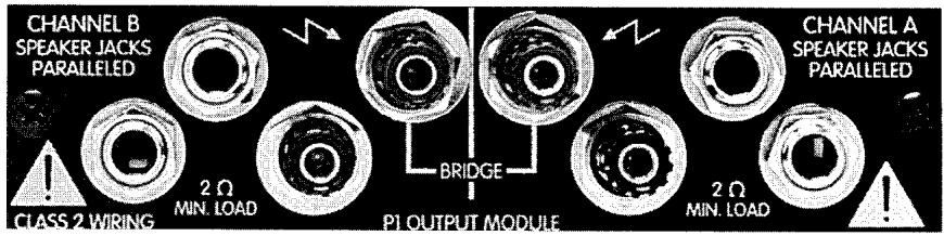
Regardless of what connections are used, the minimum parallel speaker load should always be limited to 2 ohms per channel or 4 ohms bridge mode for any application. Operation at loads of 4 ohms per channel or 8 ohms bridge mode is more desirable for sustained operation applications due to the fact that the amplifier will run much cooler at this loading. Operation above 4 ohms per channel and even open circuit conditions can always be considered safe; however, sustained operation at loads below 2 ohms could result in temporary amplifier shut down due to the thermal limits fault circuitry.
THE P1 OUTPUT MODULE REAR VIEW (16)
This diagram shows the wiring for the P1 MODULE. Note that the module itself is upside down. This is the desired position when re-connecting this and any other module. Once the correct connections to the 1/4" spades are made, then the module itself can be rotated upward and inserted into the rear panel of the CS-800S, and the panel screws replaced.

WARNING...Never
operate the CS800S with
either the output or input modules removed. Operating in this manor will allow the air flow from the fans to escape from these openings instead of flowing through the power amp and power supply components, and thereby not provide adequate cooling for these components.
Following are several other modules rear views of a different module and the various wiring schemes. The diagram above and the ones following are provided so that these modules can be correctly wired. Always double check the wiring. A miswired module can cause severe audio problems, and in the worse case, can cause loudspeaker degradation and failure. In all cases, the color-coded wires are indicated. The double red and yellow wires are the power amp outputs and are not interchangeable. The black wires are the
power amp ground connections and are interchangeable.
THE S1 OUTPUT MODULE (17)
Another output module available for this amplifier is called the S1 MODULE. This module offers dual SPEAKON® Quick Connectors and a unique patching capability to wire these connectors to meet the particular application or loudspeaker needs. The SPEAKON is a four-wire connector
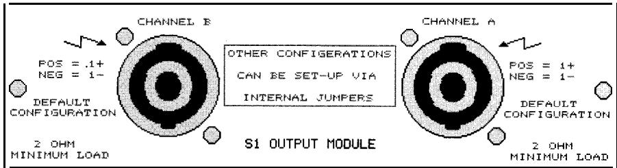
with the connections labeled 1+, 1-, 2+ , and 2- . Depending upon the loudspeaker needs, these connections can be used in various ways. The SPEAKON connector is receiving wide acceptance particularly in Europe.
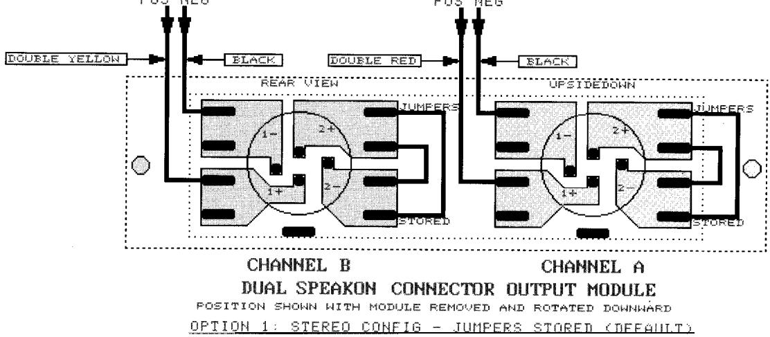
THE S1 OUTPUT MODULE REAR VIEW LOW CURRENT STEREO MODE (18) (Option 1)
This S1 module is shipped wired as follows: It as the channel signal output and 1 as the channel chassis ground. This is really the defacto standard for most low-to-medium power loudspeaker systems. This wiring allows one enclosure to be connected to channel A, and one enclosure to be connected to channel B. The 2 t and 2 - connections are simply not used in this application! In this case the 2 t and the 2 - spades are used to "store" the jumper cables for later usage.
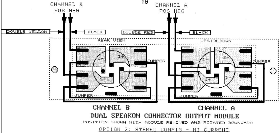
THE SI OUTPUT MODULE REAR VIEW HIGH CURRENT STEREO MODE (19) (Option 2)
Many larger loudspeaker systems use the full capability of the SPEAKON connector by paralleling 1 t and 2+ , and paralleling 1 - and 2 -. This wiring improves the current handling capability of the system and reduces losses. Most "subs" with SPEAKONs are wired this way. This module can be easily re-wired to this configuration using the supplied jumpers on the rear of the module. Normally four jumpers are plugged in a noconnect configuration for "storing". In this case, one jumper is connected between 1 t and 2+ and another jumper is connected between 1 - and 2 - for each channel. This is a total of
four jumpers. The diagram (19) shows the wiring of the jumpers.
18
CHANNEL A
POS NEG
19
20
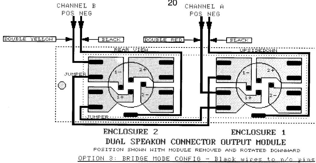
THE SI OUTPUT MODULE REAR VIEW - BRIDGE MODE (20) (Option 3)
This module can be re-wired to allow the SPEAKONs to be the bridge outputs with both in parallel. This arrangement would allow for example, two 8 ohm enclosures to be connected in parallel to the CS 800S in bridge mode. In this case the wiring is as follows: 1+ on both connectors wired to channel A signal output; 1- on both connectors wired to channel B signal output; 2+ and 2- on both
connectors not used; channel A and B chassis ground wires are not uses (plugged into isolated floating terminals)! This wiring requires one jumper per channel for a total of two; the other two are stored! Again, a wiring diagram is included and check it carefully before you proceed!
THE S1 OUTPUT MODULE REAR VIEW BI-AMP MODE (21) (Option 4)
The final wiring arrangement is really a natural progression of the SPEAKON capability with it's four wire connections. Bi-amping is really the preferred configuration for most sound reinforcement systems. It will be discussed later in this manual. The SPEAKON pins used in the typical bi-amped loudspeaker enclosure are: 1 t = LOW+
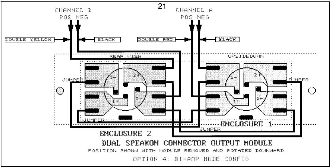
1 - = LOW-; 2+=HI+; 2 - = HI-. With the above wiring arrangement, two bi-amped, wired loudspeaker enclosures can be connected to a CS800S via the two SPEAKON connectors. First, the CS800S must be configured for bi-amp mode with each channel signal supplied from a suitable crossover, and in this case the configuration is channel A is the "lows" and channel B is the "highs". For this one, the wiring is: 1 t on both connectors wired to channel A signal output; 1 - on both connectors wired to channel A chassis ground wire; 2+ on both connectors wired to channel B signal output; 2 - on both connectors wired to channel B chassis ground wire. This configuration also requires two jumpers per channel for a total of four. Again, check the wiring of the module carefully!
INSTALLATION AND CONNECTION
The Peavey CS800S commercial series power amplifier is designed for durability in commercial installations and the quality of performance required in studio and home applications. The unit is a standard rack-mount configuration, 3 1/2" high and is cooled by two variable speed internal fans. All the input and output connections are on the back panel. The front panel contains LED indicators for power & DDT activation, detented/calibrated sensitivity controls, and a mains power switch.
INDUSTRIAL AND COMMERCIAL INSTALLATIONS
For commercial and other such installations where sustained high powered operation is required, the CS 800S should be mounted in a standard EIA 19" rack. It is not necessary to leave rack space between each amplifier in the stack, since the fan pulls air in from the rear and exhausts the hot air out the front. An adequate source of cool air must be provided for the amplifier when rack-mounted. The internal fans must have a source of air that is not preheated by other equipment. If cool, the amplifier will start up in low-speed fan operation, and will normally stay at low-speed operation unless sustained high power operating levels occur. As the amplifier heat sinks heat up the automatic thermal sensing circuitry will increase the fan speed. Depending upon signal conditions and amp loading, the fan speed may increase to a maximum value, or it may decrease to a minimum value. This situation is quite normal.
Inadequate cooling due to preheated air, a reduction of air flow caused by blockage of the amplifiers inlet/outlet ports, or severely overloading the amp may cause the amplifiers thermal sensing system to temporary shut down that particular channel. This will be indicated by the channel power LED on the front panel ceasing to illuminate. Depending upon available cooling air, operation will be restored to that channel relatively quickly, and the power LED will then be illuminated. Corrective action should be taken to determine the cause of the thermal shutdown. If the amplifier is not severely overloaded or shorted, and air flow is normal in and out of the unit, steps should be taken to provide a cooler environment for all the amplifiers. As a general rule, the cooler electronic equipment is operated, the longer its useful service life.
STUDIO AND HOME INSTALLATION:
In most low-to medium-power applications, the CS800S can be mounted in any configuration. It is desirable that, if at all possible, the unit be located at the top of an equipment stack. This will prevent possible overheating of any sensitive equipment by the hot air rising from the power amplifier. As a general rule, most home and studio requirements will never cause maximum high speed fan operation. If it does however, this may indicate that you have not taken the necessary steps to provide adequate cooling. Remember, closed up in a cabinet, the CS800S will have severe cooling problems, even at low power levels. Again, inadvertent short circuit or sustained overloaded usage could also cause temporary thermal shutdown. Most home wiring and electrical circuits are only 15 amps. Two CS 800S amplifiers could cause a power panel 15 amp circuit breaker to trip if a severe overload occurs.
BRIDGE MODE:
The bridge mode on stereo amplifiers is often misunderstood as to the actual operation and usage. In basic terms, when a two-channel amplifier is operated in bridge mode, it is converted into a single channel unit with a power rating equal to the sum of both channel's power ratings, at a load rating of twice that of the single channel rating. In this case the CS800S is rated at 600 W RMS per channel into 2 ohms. The bridge mode ratings are 1,200 W RMS into 4 Ohms (minimum load). The bridge mode operation is accomplished by placing the mode switch into the bridge position, connecting the load between the red binding posts of each channel, and then using channel A as the input channel. All channel B input functions are defeated.
Another application for bridge mode operation is to drive sound distribution systems in very large public address applications. In this mode, the CS® 800X power amplifier can actually drive 70-volt systems directly without using expensive matching transformers. The real advantage of such an approach is primarily cost. 70-volt distribution systems are very common in domestic applications where large numbers of relatively small loudspeakers are used for background music and paging. Such systems require the use of 70-volt transformers at each loudspeaker. Another common use for the bridge mode is in subwoofer applications where very high output power levels are required to reproduce extreme low frequencies. Such enclosures usually contain two or four loudspeakers to handle the high power levels involved. For bridge mode usage, the enclosure impedance must be 4 or 8 ohms; never below 4 ohms! Also make sure the enclosure can handle 1,200 watts reliably.
DDT™
Peavey's patented DDT™ compression system enables the sound man to maximize the performance of the amplifier/speaker combination by preventing the power amp from running out of headroom (clipping). This compression system is activated by a unique circuit that senses signal conditions that might overload the amplifier and reduce the amplifier's gain when clipping is imminent. The threshold of compression is clipping itself and no specific threshold control is used. This technique effectively utilizes every precious watt available for the power amplifier to reproduce the signal while at the same time minimizes clipping and distortion, and thus significantly reduces the potential of loudspeaker degradation and damage. The DDT system is automatic, hands-off approach to the problem of power amplifier clipping.
Since the CS800S power amplifier uses a circuit breaker for over-current protection, the DDT compression system plays even a more important role in the continuous performance by preventing each channel from clipping and overloading. Continuous operation at clipping can cause the circuit breaker to trip, but with the DDT activated this problem is minimized. For this reason you should always have the DDT compression system enabled.
CS® 800S SPECIFICATIONS
OUTPUT POWER: (Typical value, 120 V AC, 60 Hz)
Stereo mode, both channels driven
2 ohms, 1 kHz, 1% THD, 600 W RMS per chan
4 ohms, 1 kHz, 1% THD, 420 W RMS per chan
8 ohms, 1 kHz, 1% THD, 260 W RMS per chan
Bridge mode, mono
4 ohms, 1 kHz, 1% THD, 1,200 WRMS
8 ohms, 1 kHz, 1% THD, 840 WRMS
RATED OUTPUT POWER: (120 V AC, 60 Hz)
Stereo mode, both channels driven
4 ohms, 10 Hz to 20 kHz, 0.03% THD, 400 W RMS per chan
8 ohms, 10 Hz to 20 kHz, 0.02% THD, 240 W RMS per chan
POWER BANDWIDTH:
Stereo mode, both channels driven
@rated power, 4 ohms, <0.1% THD - 10 Hz to 50 kHz
TOTAL HARMONIC DISTORTION:
Stereo mode, both channels driven
10 Hz to 20 kHz, 4 ohm rated output, Less than 0.03%
HUM & NOISE:
Stereo mode, both channels driven
Below rated output power, 4 ohms, Greater than 100 dB
(30 kHz BW, unweighted)
DAMPING FACTOR:
Stereo mode, both channels driven
4 ohms, 100Hz Greater than 1,000
4 ohms, 10 kHz, Greater than 400
INPUT SENSITIVITY & IMPEDANCE:
Input attenuator set @ FCW
@rated output power, 4 ohms, 1.4 V RMS (+3 dBV)- 20k ohms unbalanced
CHANNEL VOLTAGE GAIN:
Input attenuator set @ FCW
Stereo mode, 4 ohms, 1kHz, 29 dB
Bridge mode, 8 ohms, 1 kHz, 35 dB
FREQUENCY RESPONSE:
Stereo mode, both channels driven
+0,-1 dB, 1 W RMS, 4 ohms, 3 Hz to 60 kHz
+0,-0.1 dB@rated output, 4 ohms, 20 Hz to 20 kHz
SLEW RATE:
Stereo mode, each channel - Greater than 40 V/uS
Bridge mode, mono, Greater than 80 V/uS
SQUARE WAVE RESPONSE:
Stereo mode, 4 ohms, 80 V P-P output
100 Hz waveform tilt, Less than 5 volts
10 KHz waveform rise-time, Less than 2 uS (0% over-shoot)
PHASE DISTORTION:
Stereo mode, 4 ohms @ rated power
20 Hz leading waveform - Less than 6 degrees
20 KHz lagging waveform - Less than 15 degrees
POWER CONSUMPTION:
Stereo mode, both channels driven
@ rated output power, 4 ohms, 10 A @ 120 V AC
COOLING SYSTEM:
Dual continuously variable speed DC fans
DDT™ COMPRESSION SYSTEM -Automatic, switchable with LED indicator
DIMENSIONS &WEIGHT:
:Height 3.50'' (8.9cm)
Width 19^ (48.3 cm)
:Depth 17^ (43.2cm)
Weight 23 lbs (10.5kg)
Specifications subject to change without notice.
MANUAL DEL PROPIETARIO DEL AMPLIFICADOR DE POTENCIA CS® 800S
PEAVEY ELECTRONICS CORPORATION ("PEAVEY") warrants this product, EXCEPT for covers, footswitches, patchcords, tubes and meters, to be free from defects in material and workmanship for a period of one (1) year from date of purchase, PROVIDED, however, that this limited warranty is extended only to the original retail purchaser and is subject to the conditions, exclusions, and limitations hereinafter set forth:
PEAVEY 90-DAY LIMITED WARRANTY ON TUBES AND METERS
If this product contains tubes or meters, Peavey warrants the tubes or meters contained in the product to be free from defects in material and workmanship for a period of ninety (90) days from date of purchase; PROVED, however, that this limited warranty is extended only to the original retail purchaser and is also subject to the conditions, exclusions, and limitations hereinafter set forth.
CONDITIONS, EXCLUSIONS, AND LIMITATIONS OF LIMITED WARRANTYES
These limited warranties shall be void and of no effect, if:
a. The first purchase of the product is for the purpose of resale; or
b. The original retail purchase is not made from an AUTHORIZED PEAVEY DEALER; or
c. The product has been damaged by accident or unreasonable use, neglect, improper service or maintenance, or other causes not arising out of defects in material or workmanship; or
d. The serial number affixed to the product is altered, defaced, or removed.
In the event of a defect in material and/or workmanship covered by this limited warranty, Peavey will:
a. In the case of tubes or meters, replace the defective component without charge.
b. In other covered cases (i.e., cases involving anything other than covers, footswitches, patchcords, tubes or meters), repair the defect in material or workmanship or replace the product, at Peavey's option; and provided, however, that, in any case, all costs of shipping, if necessary, are paid by you, the purchaser.
THE WARRANTY REGISTRATION CARD SHOULD BE ACCURATELY COMPLETED AND MAILED TO AND RECEIVED BY PEAVEY WITHIN FOURTEEN (14) DAYS FROM THE DATE OF YOUR PURCHASE.
In order to obtain service under these warranties, you must:
a. Bring the defective item to any PEAVEY AUTHORIZATION DEALER or AUTHORIZATION PEAVEY SERVICE CENTER and present therewith the ORIGINAL PROOF OF PURCHASE supplied to you by the AUTHORIZATION PEAVEY DEALER in connection with your purchase from him of this product. If the DEALER or SERVICE CENTER is unable to provide the necessary warranty service you will be directed to the nearest other PEAVEY AUTHORIZATION DEALER or AUTHORIZATION PEAVEY SERVICE CENTER which can provide such service.
OR
b. Ship the defective item, prepaid, to:
PEAVEY ELECTRONICS CORPORATION
International Service Center
326 Hwy. 11 & 80 East
Meridian, MS 39301
including therewith a complete, detailed description of the problem, together with a legible copy of the original PROOF OF PURCHASE and a complete return address. Upon Peavey's receipt of these items: If the defect is remedial under these limited warranties and the other terms and conditions expressed herein have been complied with, Peavey will provide the necessary warranty service to repair or replace the product and will return it, FREIGHT COLLECT, to you, the purchaser.
Peavey's liability to the purchaser for damages from any cause whatsoever and regardless of the form of action, including negligence, is limited to the actual damages up to the greater of $500.00 or an amount equal to the purchase price of the product that caused the damage or that is the subject of or is directly related to the cause of action. Such purchase price will be that in effect for the specific product when the cause of action arose. This limitation of liability will not apply to claims for personal injury or damage to real property or tangible personal property allegedly caused by Peavey's negligence. Peavey does not assume liability for personal injury or property damage arising out of or caused by a non-Peavey alteration or attachment, nor does Peavey assume any responsibility for damage to interconnected non-Peavey equipment that may result from the normal functioning and maintenance of the Peavey equipment.
UNDER NO CIRCUMSTANCES WILL PEAVEY BE LIABLE FOR ANY LOST PROFITS, LOST SAVINGS, ANY INCIDENTAL DAMAGES, OR ANY CONSEQUENTIAL DAMAGES ARISING OUT OF THE USE OR INABILITY TO USE THE PRODUCT, EVEN IF PEAVEY HAS BEEN ADVISED OF THE POSSIBILITY OF SUCH DAMAGES.
THESE LIMITED WARRANTY ARE IN LIEU OF ANY AND ALL WARRANTYES, EXRESSED OR IMPLIED, INCLUDING, BUT NOT LIMITED TO, THE IMPLIED WARRANTY OF MERCHANTABILITY AND FITNESS FOR A PARTICULAR USE; PROVIDED, HOWEVER, THAT IF THE OTHER TERMS AND CONDITIONS NECESSARY TO THE EXISTENCE OF THE EXPRESSED, LIMITED WARRANTY, AS HEREINABOVE STATED, HAVE BEEN COMPLIED WITH, IMPLIED WARRANTY ARE NOT DISCLAIMED DURING THE APPLICABLE ONE-YEAR OR NINETY-DAY PERIOD FROM DATE OF PURCHASE OF THIS PRODUCT.
SOME STATES DO NOT ALLOW LIMITATION ON HOW LONG AN IMPLIED WARRANTY LASTS, OR THE EXCLUSION OR LIMITATION OF INCIDENTAL OR CONSEQUENTIAL DAMAGES, SO THE ABOVE LIMITATIONS OR EXCLUSIONS MAY NOT APPLY TO YOU. THESE LIMITED WARRANTYES GIVE YOU SPECIFIC LEGAL RIGHTS, AND YOU MAY ALSO HAVE OTHER RIGHTS WHICH MAY VARY FROM STATE TO STATE.
THESE LIMITED WARRANTY ARE THE ONLY EXPRESSED WARRANTYES ON THIS PRODUCT, AND NO OTHER STATEMENT, REPRESENTATION, WARRANTY, OR AGREEMENT BY ANY PERSON SHALL BE VALID OR BINDING UPON PEAVEY.
In the event of any modification or disclaimer of expressed or implied warranties, or any limitation of remedies, contained herein conflicts with applicable law, then such modification, disclaimer or limitation, as the case may be, shall be deemed to be modified to the extent necessary to comply with such law.
Your remedies for breach of these warranties are limited to those remedies provided herein and Peavey Electronics Corporation gives this limited warranty only with respect to equipment purchased in the United States of America.
INSTRUCTIONS -WARRANTY REGISTRATION CARD
- Mail the completed WARRANTY REGISTRATION CARD to:
PEAVEY ELECTRONICS CORPORATION
P.O. BOX 2898
Meridian, MS 39302-2898
a. Keep the PROOF OF PURCHASE. In the event warranty service is required during the warranty period, you will need this document. There will be no identification card issued by Peavey Electronics Corporation.
- IMPORTANCE OF WARRANTY REGISTRATION CARDS AND NOTIFICATION OF CHANGES OF ADDRESSES:
a. Completion and mailing of WARRANTY REGISTRATION CARDS — Should notification become necessary for any condition that may require correction, the REGISTRATION CARD will help ensure that you are contacted and properly notified.
b. Notice of address changes - If you move from the address shown on the WARRANTY REGISTRATION CARD, you should notify Peavey of the change of address so as to facilitate your receipt of any bulletins or other forms of notification which may become necessary in connection with any condition that may require dissemination of information or correction. - You may contact Peavey directly by telephoning (601) 483-5365.
IMPORTANT SAFETY INSTRUCTIONS
WARNING: When using electric products, basic cautions should always be followed, including the following.
- Read all safety and operating instructions before using this product.
- All safety and operating instructions should be retained for future reference.
- Obey all cautions in the operating instructions and on the back of the unit.
- All operating instructions should be followed.
- This product should not be used near water, i.e., a bathtub, sink, swimming pool, wet basement, etc.
- This product should be located so that its position does not interfere with its proper ventilation. It should not be placed flat against a wall or placed in a built-in enclosure that will impede the flow of cooling air.
- This product should not be placed near a source of heat such as a stove, radiator, or another heat producing amplifier.
- Connect only to a power supply of the type marked on the unit adjacent to the power supply cord.
- Never break off the ground pin on the power supply cord. For more information on grounding, write for our free booklet "Shock Hazard and Grounding."
- Power supply cords should always be handled carefully. Never walk or place equipment on power supply cords. Periodically check cords for cuts or signs of stress, especially at the plug and the point where the cord exits the unit.
- The power supply cord should be unplugged when the unit is to be unused for long periods of time.
- If this product is to be mounted in an equipment rack, rear support should be provided.
- Metal parts can be cleaned with a damp rag. The vinyl covering used on some units can be cleaned with a damp rag or an ammonia-based household cleaner if necessary. Disconnect unit from power supply before cleaning.
- Care should be taken so that objects do not fall and liquids are not spilled into the unit through the ventilation holes or any other openings.
- This unit should be checked by a qualified service technician if:
a. The power supply cord or plug has been damaged.
b. Anything has fallen or been spilled into the unit.
c. The unit does not operate correctly.
d. The unit has been dropped or the enclosure damaged.
- The user should not attempt to service this equipment. All service work should be done by a qualified service technician.
- This product should be used only with a cart or stand that is recommended by Peavey Electronics.
- Exposure to extremely high noise levels may cause a permanent hearing loss. Individuals vary considerably in susceptibility to noise induced hearing loss, but nearly everyone will lose some hearing if exposed to sufficiently intense noise for a sufficient time.
The U.S. Government's Occupational Safety and Health Administration (OSHA) has specified the following permissible noise level exposures.
| Duration Per Day In Hours | Sound Level dBA, Slow Response |
| 8 | 90 |
| 6 | 92 |
| 4 | 95 |
| 3 | 97 |
| 2 | 100 |
| I 1/2 | 102 |
| 105 | |
| 1/2 | 110 |
| 1/4 or less | 115 |
According to OSHA, any exposure in excess of the above permissible limits could result in some hearing loss. Ear plugs or protectors in the ear canals or over the ears must be worn when operating this amplification system in order to prevent a permanent hearing loss if exposure is in excess of the limits as set forth above. To ensure against potentially dangerous exposure to high sound pressure levels, it is recommended that all persons exposed to equipment capable of producing high sound pressure levels such as this amplification system be protected by hearing protectors while this unit is in operation.
SAVE THESE INSTRUCTIONS!
SPEAKON® IS A REGISTERED TRADEMARK OF NEUTRIK® AG

Peavey Electronics, 711 A Street, Meridian, MS 39301 (601) 483-5365
Fax (601)486- 1278 . http://www.peavey.com . AOL Keyword: Peavey . CompuServe: Go Peavey