
MP 600 - Power amplifier PEAVEY - Free user manual and instructions
Find the device manual for free MP 600 PEAVEY in PDF.
User questions about MP 600 PEAVEY
0 question about this device. Answer the ones you know or ask your own.
Ask a new question about this device
Download the instructions for your Power amplifier in PDF format for free! Find your manual MP 600 - PEAVEY and take your electronic device back in hand. On this page are published all the documents necessary for the use of your device. MP 600 by PEAVEY.
USER MANUAL MP 600 PEAVEY
text_image
PEAVY® 300MΩ W/15A MASTERN SCALALIZATION 32 dB Digital Revers MP™ 600 200 Watts With 80 P-Discharge Simulation VOUTS CAPS CAPS CAPS CAPS CAPS CAPS CAPS CAPS CAPS CAPS CAPS CAPS CAPS CAPS CAPS CAPS CAPS CAPS CAPS CAPS CAPS CAPS CAPS CAPS CAPS CAPS CAPS CAPS CAPS CAPS CAPS CAPS CAPS CAPs CAPs CAPs CAPs CAPs CAPs CAPs CAPs CAPs CAPs CAPs CAPs CAPs CAPs CAPs CAPs CAPs CAPs CAPs CAPs CAPs CAPs CAPs CAPs CAPs CAPs CAPs CAPs CAPs CAPs CAPs CAPs CAPs CAPs
Intended to alert the user to the presence of uninsulated “dangerous voltage” within the product’s enclosure that may be of sufficient magnitude to constitute a risk of electric shock to persons.

Intended to alert the user of the presence of important operating and maintenance (servicing) instructions in the literature accompanying the product.
CAUTION: Risk of electrical shock — DO NOT OPEN!
CAUTION: To reduce the risk of electric shock, do not remove cover. No user serviceable parts inside. Refer servicing to qualified service personnel.
WARNING: To prevent electrical shock or fire hazard, do not expose this appliance to rain or moisture. Before using this appliance, read the operating guide for further warnings.

WARNING: When using electrical products, basic cautions should always be followed, including the following:
- Read these instructions.
- Keep these instructions.
- Heed all warnings.
- Follow all instructions.
- Do not use this apparatus near water.
- Clean only with a dry cloth.
- Do not block any of the ventilation openings. Install in accordance with manufacturer's instructions.
- Do not install near any heat sources such as radiators, heat registers, stoves or other apparatus (including amplifiers) that produce heat.
- Do not defeat the safety purpose of the polarized or grounding-type plug. A polarized plug has two blades with one wider than the other. A grounding type plug has two blades and a third grounding plug. The wide blade or third prong is provided for your safety. If the provided plug does not fit into your outlet, consult an electrician for replacement of the obsolete outlet.
- Protect the power cord from being walked on or pinched, particularly at plugs, convenience receptacles, and the point they exit from the apparatus.
- Note for UK only: If the colors of the wires in the mains lead of this unit do not correspond with the terminals in your plug, proceed as follows:
a) The wire that is colored green and yellow must be connected to the terminal that is marked by the letter E, the earth symbol, colored green or colored green and yellow.
b) The wire that is colored blue must be connected to the terminal that is marked with the letter N or the color black.
c) The wire that is colored brown must be connected to the terminal that is marked with the letter L or the color red. - Only use attachments/accessories provided by the manufacturer.
- Use only with a cart, stand, tripod, bracket, or table specified by the manufacturer, or sold with the apparatus. When a cart is used, use caution when moving the cart/apparatus combination to avoid injury from tip-over.
- Unplug this apparatus during lightning storms or when unused for long periods of time.
- Refer all servicing to qualified service personnel. Servicing is required when the apparatus has been damaged in any way, such as power-supply cord or plug is damaged, liquid has been spilled or objects have fallen into the apparatus, the apparatus has been exposed to rain or moisture, does not operate normally, or has been dropped.
- Never break off the ground pin. Write for our free booklet “Shock Hazard and Grounding.” Connect only to a power supply of the type marked on the unit adjacent to the power supply cord.
- If this product is to be mounted in an equipment rack, rear support should be provided.
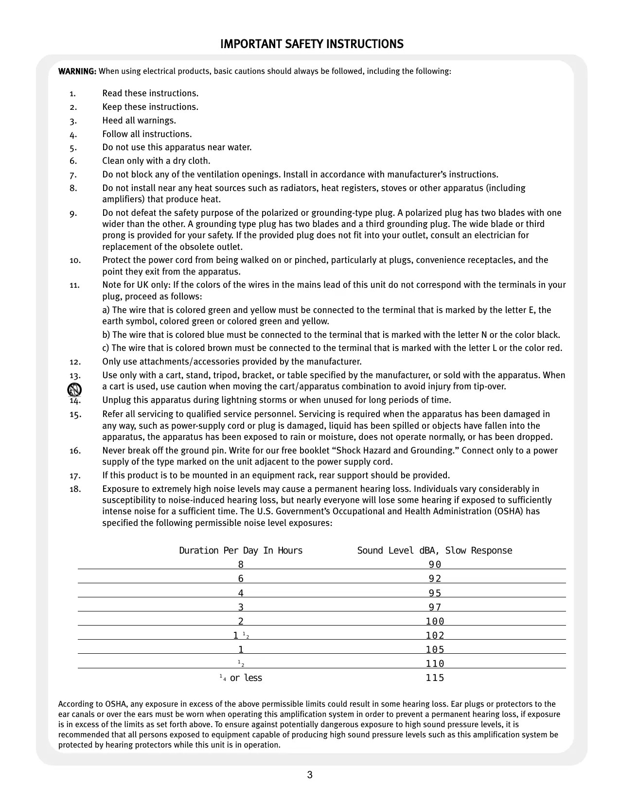
- Exposure to extremely high noise levels may cause a permanent hearing loss. Individuals vary considerably in susceptibility to noise-induced hearing loss, but nearly everyone will lose some hearing if exposed to sufficiently intense noise for a sufficient time. The U.S. Government's Occupational and Health Administration (OSHA) has specified the following permissible noise level exposures:
| Duration Per Day In Hours | Sound Level dBA, Slow Response |
| 8 | 90 |
| 6 | 92 |
| 4 | 95 |
| 3 | 97 |
| 2 | 100 |
| 1^1/_f | 102 |
| 1 | 105 |
| ^1/_f | 110 |
| ^1/_f or less | 115 |
According to OSHA, any exposure in excess of the above permissible limits could result in some hearing loss. Ear plugs or protectors to the ear canals or over the ears must be worn when operating this amplification system in order to prevent a permanent hearing loss, if exposure is in excess of the limits as set forth above. To ensure against potentially dangerous exposure to high sound pressure levels, it is recommended that all persons exposed to equipment capable of producing high sound pressure levels such as this amplification system be protected by hearing protectors while this unit is in operation.
ENGLISH
MP ^TM 600
POWERED MIXER
Thank you for purchasing the Peavey MP ^™ 600! The MP ^™ 600 is a seven-channel mixer with a variety of built-in features, including a dedicated line input channel (summed input for a tape deck or other line level device), 32-bit digital reverb, channel and master equalizers and a 200 Watt power amplifier, all housed in a rugged topbox package.
This owners manual explains the MP 600's features and its proper operation. Each section of the mixer is separated into numbered illustrations. In each illustration you will be directed to a controls' explanation of operation by its corresponding reference number.
FEATURES:
- Seven total input channels
- Reverb control on each channel
- Six mono input channels
• One mono (summed) input channel with stereo RCA and 1/4" jacks - Two-band equalizer on each channel
• 1/4" and XLR inputs (Channels 1 — 6 only) - Master effects output (1/4" send jack)
- Main output (1/4" send jack)
• Master four-band equalizer
• RCA tape record output (summed)
• Master level and reverb controls
• 200 Watt power amp
text_image
1 POWER I 2 FUSE 6A/250V 120 VAC 60 Hz 165 WATTS 3 4 SPARKER OUTPUTS CLASS 2 WIRING 200 WATTS/ 4 OHMS (28.3V RMS) 150 WATTS/ 8 OHMS (34.6V RMS) 4 OR 8 OHM LOAD (4 OHMS MIN. LOAD) A PRODUCT OF PEAVEY ELECTRONICS CORP. MADE IN CHINA CAUTION RISK OF ELECTRIC SHOCK DO NOT OPEN WARNING TO REDUCE THE RISK OF FIRE OR ELECTRIC SHOCK DO NOT EXPOSE THE EQUIPMENT TO RAIN OR MOISTURE, TO PREVENT THE RISK OF FIRE H/AZARD REPLACE WITH SAME TYPE 250 VOLT FUSE, AVIS: RISQUE DE CHOC ELECTRIQUE - NE PAS OUWIR REPACKER PAR INJ USIBLE DE MESIE TYPE ETTE 250 VOLT. PIN 1 = GND PIN 2 = ROS PIN 3 = NEGPOWER
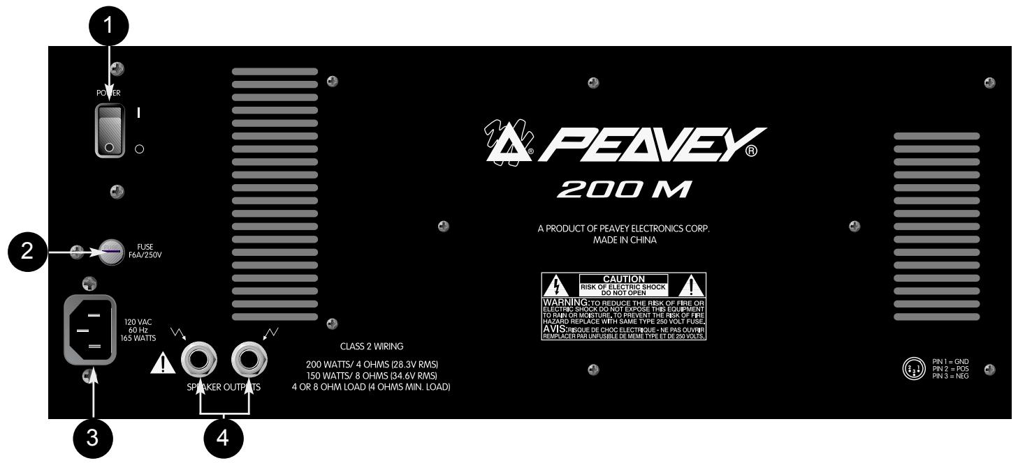
This section describes the proper application of AC power to your MP 600. To ensure the safety of you and your MP 600, please pay close attention to any designated cautions.
1. POWER SWITCH
Used to turn AC mains power on or off.
2. FUSE
The fuse is located within the cap of the fuseholder. If the fuse should fail, IT MUST BE REPLACED WITH THE SAME TYPE AND VALUE IN ORDER TO AVOID DAMAGE TO THE EQUIPMENT AND TO PREVENT VOIDING THE WARRANTY. If the amp repeatedly blows fuses, it should be taken to a qualified service center for repair.

WARNING: THE FUSE SHOULD ONLY BE REPLACED WHEN THE POWER CORD HAS BEEN DISCONNECTED FROM ITS POWER SOURCE.
3. REMOVABLE AC POWER CORD
This receptacle is for the IEC line cord (included), which provides AC power to the unit. Connect the line cord to this connector and to a properly grounded AC supply. Damage to the equipment may occur if an improper line voltage is used. (See voltage marking on unit.) Never remove or cut the ground pin of the line cord plug. This unit is supplied with a properly rated line cord. When lost or damaged, replace this cord with one of the proper ratings.
(For UK Only) As the colours of the wires in the mains lead of this apparatus may not correspond with the coloured markings identifying the terminals in your plug, proceed as follows: • The wire which is coloured green and yellow must be connected to the terminal which is marked by the letter E or by the earth symbol, or coloured green or green and yellow. • The wire which is coloured blue must be connected to the terminal which is marked with the letter N or coloured black. • The wire which is coloured brown must be connected the terminal which is marked with the letter L or the coloured red.
SPEAKER CONNECTIONS
This section will help you locate the two speaker output jacks on the rear of your MP 600. Though there are two output jacks, they are mono (parallel) and not stereo. (2 — 8 ohms speakers)

WARNING: NEVER ALLOW YOUR TOTAL SPEAKER IMPEDANCE TO DROP BELOW THE INDICATED MINIMUM IMPEDANCE.
4. SPEAKER OUTPUTS
Two parallel 1/4" jacks are provided at the output of the power amplifier. Minimum speaker impedance (minimum load) is 4 ohms.
CHANNEL (1—6) FEATURES
The following section describes Channels 1 — 6. Each of these input channels are identical. Some features listed below can be found on Channel 7 as well.
text_image
1 HIGH 0 3 6 9 -15 +15 -12 12 10 9 LOW 3 0 3 6 9 -15 +15 -12 12 REVERB 4 5 6 7 8 10 3 2 1 0 GAIN 4 5 6 7 8 -2 9 10 LINE MIC INPUTS 15V PHANTOM POWER 55. MIC INPUT
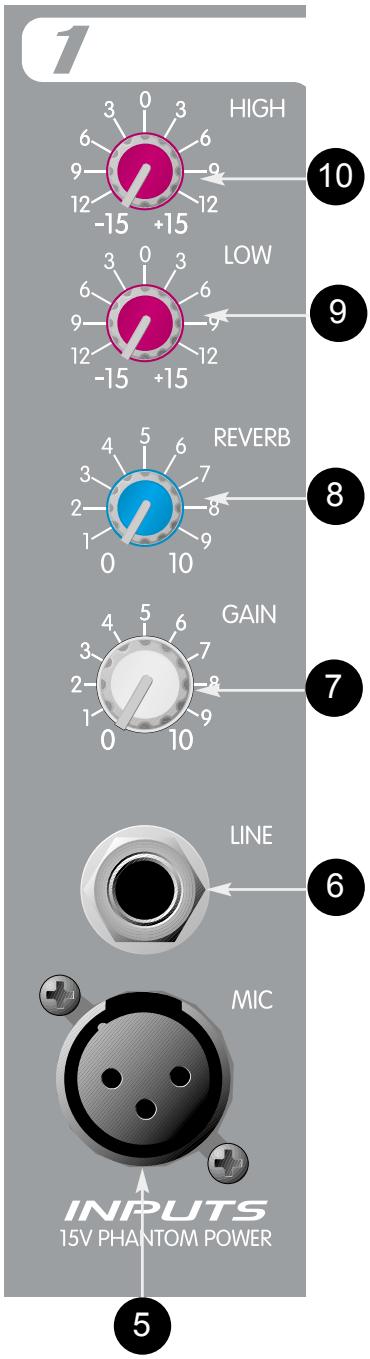
XLR balanced low impedance channel input optimized for a microphone or other low impedance source. Pin 2 is the positive input. This connector has +15V phantom power supply on pins 2 and 3 at all times. (Pin 1 is the ground reference.)

WARNING: SOME PRODUCTS, INCLUDING SOME WIRELESS MICROPHONE UNITS, CAN BE DAMAGED BY PHANTOM POWER. CHECK THE OPERATING INSTRUCTIONS OF THE PRODUCT YOU WISH TO CONNECT TO THE MIC INPUT BEFORE CONNECTING. PHANTOM POWER DOESN'T AFFECT LOW IMPEDANCE DYNAMIC MICROPHONES.
6. LINE INPUT
1/4" unbalanced input that accepts line level sources equipped with a 1/4" plug (TS). The two inputs (XLR and 1/4") cannot be used simultaneously.
7. GAIN
Sets the level of the individual channel in the mix.
8. REVERB
Sets the level to internal reverb from channel and must be used in conjunction with the master reverb level. It is post gain and will be affected by the Gain adjustment (7). The Reverb control also determines the level of signal sent to the Effects Output (14).
9. LOW EQ
A shelving type of active tone control that varies the bass frequency levels ±15 dB at 100 Hz. It will add depth to thin signals, or clean up muddy ones.
10. HIGH EQ
A shelving type of active tone control that varies the treble frequency level ±15 dB at 10 kHz. It is designed to remove noise or to add brilliance to the signal, depending on the quality of the source.
CHANNEL SEVEN FEATURES
Channel 7 has two 1/4" line inputs and RCA tape inputs. These inputs are summed. They add (sum) the left and right signals of a stereo source such as a tape or CD player.
11. LINE AND TAPE INPUTS
RCA and 1/4" jacks accept a stereo input from a CD player, tape deck or keyboard. These inputs are summed internally into a mono signal. See page 10 for operational note.

CAUTION: Care should be taken not to record on a deck that has its outputs connected to the line/tape input jacks and have the Channel 7 Gain control turned up, or Feedback will occur. You may disconnect the tape inputs on the MP 600 if recording on the same tapedeck. Or, you may use a separate tape deck to play and record at the same time.
flowchart
graph TD
    A["PEAVEY® DESIGNED IN U.S.A."] --> B["MASTER EQUALIZATION"]
    B --> C["32 Bit Digital Reverb"]
    C --> D["Digital Reverb Level"]
    C --> E["Master Level"]
    D --> F["MP TM 600 200 Watts With DDTTM Distortion Elimination"]
    E --> F
    F --> G["TAPE"]
    G --> H["CHANNEL 7 SUMMED INPUTS"]
    G --> I["REC OUT"]
    G --> J["REVERB DEFRAT"]
    G --> K["EFFECTS"]
    G --> L["MAIN OUTPUTS"]
    H --> M["INPUTS SUMMED"]
    I --> N["LINE"]
    J --> O["POWER"]
    K --> P["12"]
    L --> Q["15"]
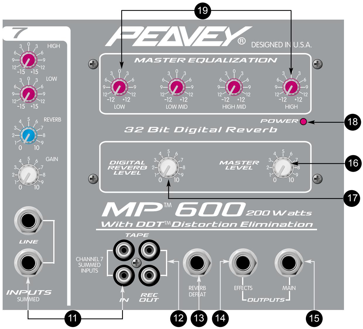
MASTER FEATURES
12. TAPE [REC] OUTPUTS
RCA output jacks that provide a monaural signal to the left and right inputs of a stereo tape deck. This is the main signal taken after the Master Level (16) and the Master EQ.
13. REVERB FOOTSWITCH
Provided for connection of the optional remote footswitch. The footswitch is used to activate/defeat the reverb. You may use the ON/OFF single-button switch #0051000.
14. EFFECTS OUTPUT
Plugging into this mono (TS) 1/4" output disconnects the internal reverb, allowing you to utilize external effects devices. In order to return the signal from the external effects unit, use the summing inputs of Channel 7.
OPERATION NOTE: When using Channel 7 as an effects return, it is important that you turn the Channel 7 Reverb control all the way down ("0" position). Failure to do so may cause oscillation or other strange effects. This is due to feeding signal returned from the effects loop back into the effects loop resulting in a feedback.
15. MAIN OUTPUT
1/4" unbalanced output that can be used as a source for an external amplifier/speaker system, feed to other mixers or a tape deck. This signal is taken after the master four-band equalizer.
16. MASTER LEVEL CONTROL
Controls the overall volume level of the system.
17. MASTER REVERB LEVEL CONTROL
Controls the amount of reverb that will be heard in the main mix.
18. POWER LED
Illuminates when AC power is being supplied to the mixer.
Provides ±12 dB equalization at each center frequency. EQ boost is obtained by moving a particular EQ band's control above the "0" position. EQ cut is obtained by moving a particular EQ band's control below the "0" position. The following list describes each EQ control and its center frequency.
Low - shelving type - 40 Hz
Low Mid - peak type - 300 Hz
High Mid - peak type - 2 kHz
High - shelving type - 10 kHz
OPERATION NOTE: This equalizer is designed to provide room equalization, feedback control and system tone control. No amount of equalization will correct the response curve of a poor loudspeaker. Always begin with all controls in the “0” position and avoid excessively boosting large segments of the audio passband, which could limit the system’s dynamic range.
MP 600 Specifications
Input Specifications:
| Function | Input Z (ohms) Min. | Input Gain Settings | Input Levels | Bal./ UnBal. | Connector | ||
| Min.** | Nominal* | Max. | |||||
| Microphone (150 ohms) | 2 k | Max. Gain (50 dB) | -56 dBu | -27 dBu | -8 dBu | Bal. | XLR: Pin 1 Gnd, Pin 2 (+), Pin 3 (-) |
| Line | 22 k | Max. Gain (20 dB) | -26 dBu | +2.21 dBu | +30 dBu | Unbal. | 1/4" TS; Tip (+), Sleeve Ground |
| Aux Inputs | 100 k | Max. Gain (20 dB) | -26 dBu | +2.21 dBu | +22 dBu | Unbal. | 1/4" TS; Tip (+), Sleeve Ground |
| Tape | 100 k | Max. Gain (20 dB) | -26 dBu | +2.21 dBV | +22 dBu | Unbal. | RCA Jacks |
Nom. output: 2.21 dBu = 0 dBV = 1 V RMS
** Min. input level (Sensitivity) is the smallest signal that will produce nominal output (2 dBu) with channel and master controls set for maximum gain.
* Nominal settings are defined as all controls set at 0 dB (or 50% rotation for rotary pots).
Output Specifications:
| Function | Minimum Load Z | Output Level | Bal./ Unbal. | Connector (Ohms) | |
| Nominal | Max | ||||
| Main | 600 | +2.21 dBu | +20 dBu | Unbal. | 1/4" TS Tip (+) Sleeve Ground |
| Monitor | 600 | +2.21 dBu | +20 dBu | Unbal. | 1/4" TS: Tip (+) Sleeve Ground |
| Tape | 10 k | +2.21 dBu | +20 dBu | Unbal. | RCA |
Gain:
Mic input to main output: 60 dB (Max. gain)
Line input to main output: 30 dB (Max. gain)
Aux input to main output: 30 dB (Max. gain)
Frequency response:
Mic input (XLR) to main output: 20 Hz to 20 kHz +0 dB/-1 dB
Line input to main output: 20 Hz to 20 kHz +0 dB/-1 dB
Total harmonic distortion (THD):
<0.05% 20 Hz to 20 kHz Mic to Main/Monitor output at nominal level (22 Hz - 80 kHz BW) <0.05% 20 Hz to 20 kHz Line to Main/Monitor output at nominal level (22 Hz - 80 kHz BW)
Hum and Noise:
| Output | Residual NoiseRef. 0 dBu | S/N Ratio +4Ref. 2.21 dBu | Test Conditions |
| Main | -95 dBu | 97 dB | All controls down |
| -85 dBu | 87 dB | One channel nominalMaster level nominal |
(Hum and noise measurements: 22 Hz to 22 kHz BW)
Nom. output: 2.21 dBu = 0 dBV=1V
S/N ratio:
85 dB below rated output (200 W RMS) Mic to speaker output
90 dB below rated output (200 W RMS) Line to speaker output
Equivalent input noise (EIN):
-117 dBu (Input terminated with 150 Ohms)
Channel EQ:
High EQ: ±15 dB @ 10 kHz
Low EQ: ±15 dB @ 100 Hz
Master EQ:
High EQ: ±12 dB @ 10 kHz
High Mid EQ: ±12 dB @ 2 kHz
Low Mid EQ: ±12 dB @ 300 Hz
Low EQ: 12 dB @ 40 Hz
Phantom power:
+15 VDC
Power amp specifications:
200 M Module with DDT™
Power and load:
150 Watt RMS into 8 Ohms
200 Watt RMS into 4 Ohms
2 Ohms not recommended
Frequency response:
20 Hz - 20 kHz + 0 dB/-1 dB
Total harmonic distortion (THD):
<0.03% at rated output @ 1 kHz
Power requirements (1/8th power):
Dom: 120 VAC 60 Hz 165 Watts Max
Exp: 220-230 VAC/240 VAC 50/60 Hz 165 Watts Max
MP ^TM 600
LEVEL DIAGRAM
TYPICAL EACH CHANNEL
MASTER SECTION
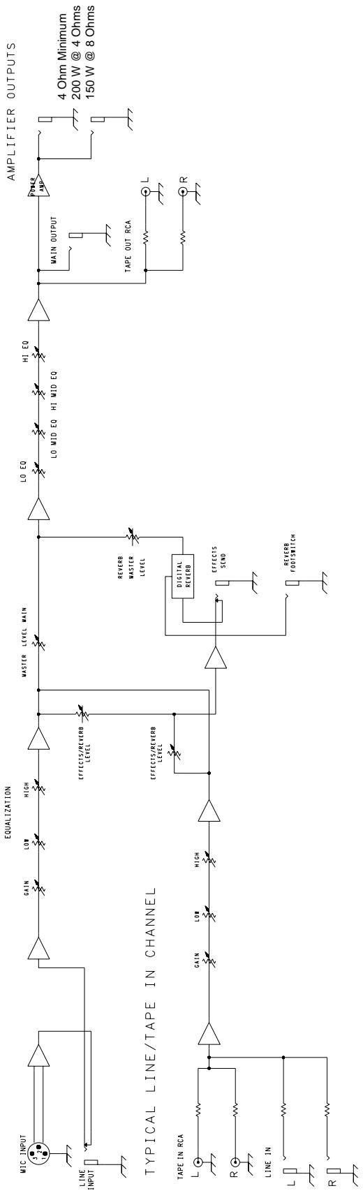
flowchart
graph TD
    A["Typical Line/ Tape IN CHANNEL"] --> B["Line INPUT"]
    A --> C["TAPIN RCA"]
    A --> D["LINE IN"]

    B --> E["MIC INPUT"]
    C --> F["GAIN"]
    C --> G["LOW"]
    C --> H["HIGH"]

    E --> I["EQUALIZATION"]
    F --> I
    G --> I
    H --> I

    I --> J["MASTER LEVEL MAIN"]
    J --> K["LO EQ"]
    J --> L["LO MID EQ"]
    J --> M["HI MID EQ"]

    K --> N["POWER AND POWER"]
    L --> O["TAPE OUT RCA"]
    M --> P["AMPLIFIER OUTPUTS"]

    Q["TAPE IN RCA"] --> R["L"]
    S["LINE IN"] --> T["L"]
    U["R"] --> V["R"]

    W["REVERB FOOTSWITCH"] --> X["DIGITAL REVERB"]
    Y["EFFECTS/REVERB LEVEL"] --> Z["REVERB MASTER LEVEL"]

    AA["4 Ohm Minimum 200 W @ 4 Ohms 150 W @ 8 Ohms"] --> AB["POWER AND TAPE OUT RCA"]

    AC["4 Ohm Minimum 200 W @ 4 Ohms 150 W @ 8 Ohms"] --> AD["AMPLIFIER OUTPUTS"]
MP™ 600
HOOK UP DIAGRAM

natural_image
Black speaker with sound waves and 'Tobet' logo (no text or symbols on body)112 TLS ^TM

natural_image
Black speaker with sound waves and 'Tobet' logo (no text or symbols on body)Outputs on back
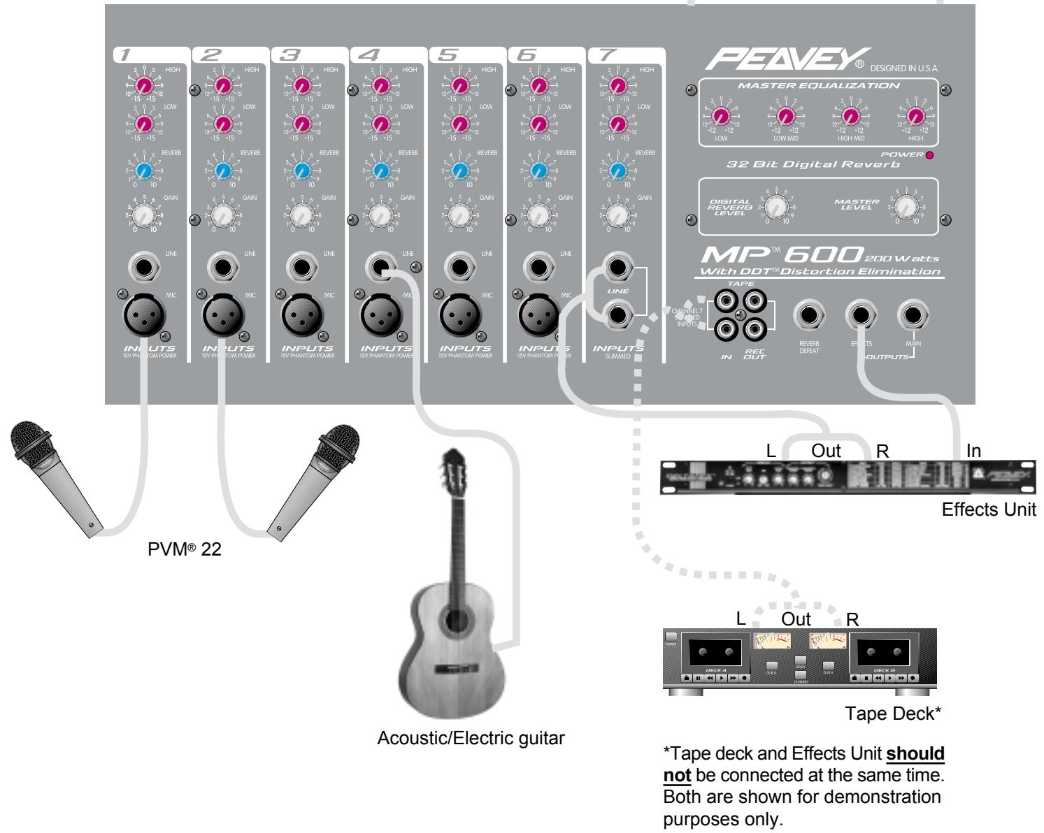
text_image
PEAVEY® DESIGNED IN U.S.A. MASTER EQUALIZATION 32 Bit Digital Reverb POWER DIGITAL REVERD LEVEL MASTER LEVEL MP™ 600 200 Watts With DDT™ Distortion Elimination TAPE CHANNEL7 SWEED INPUTS IN REC OUT REVERB DEEAT EFFECTS MAIN L Out R In Effects Unit L Out R Tape Deck* *Tape deck and Effects Unit should not be connected at the same time. Both are shown for demonstration purposes only. PVM® 22 ACoustic/Electric guitarESPAÑOL
MP ^TM 600
MEZCLADORA AMPLIFICADA
3. CORDON D'ALIMENTATION IEC
Low - type shelving - 40 Hz
Low Mid - type peak - 300 Hz
High Mid - type peak - 2 kHz
High - type shelving - 10 kHz
text_image
PEAVEY® 200 M A PRODUCT OF PEAVEY ELECTRONICS CORP. MADE IN CHINA 1 POWER I 2 FUSE F44/250V 3 230V/°C 50/60 Hz 163 WAYS 4 SPEAKER OUTPUTS CLASS 2 WIRING 200 WATTS/ 4 OHMS (28.3V RMS) 150 WATTS/ 8 OHMS (34.6V RMS) 4 OR 8 OHM LOAD (4 OHMS MIN. LOAD) CAUTION RISK OF ELECTRIC SHOCK DO NOT OPEN WARNING TO REDUCE THE RISK OF FIRE OR ELECTRIC SHOCK DO NOT EXPOSE THIS EQUIPMENT TO RAIN OR MOUSTURE, TO PREVENT THE RISK OF FIRE HAZARD REPLACE WITH SAME TYPE 250 VOLT FUSE, AVIS MISQUE DE CHOC ELECTRIQUE - NE PAS OUVRIR REMACENT BAR AND SLEE CE MEVE TYPE ET EC-200 VOLTS PIN 1 = GND PIN 2 = POS PIN 3 = NEG12. TAPE [REC] OUTPUT (TAPE [REC] -AUSGÄNGE)
Low - shelving type - 40 Hz
Low Mid - peak type - 300 Hz
High Mid - peak type - 2 kHz
High - shelving type - 10 kHz
![PEAVEY MP 600 - TAPE [REC] OUTPUT (TAPE [REC] -AUSGÄNGE) - 1](/content/2020/04/169546/images/2106119bbe92b12d649816d686554ed04159b25749e31688f0c8755b30d8b943.jpg)
IMPORTANT SAFETY INSTRUCTIONS
WARNING: When using electric products, basic cautions should always be followed, including the following:
-
Read these instructions.
-
Keep these instructions.
-
Heed all warnings.
-
Follow all instructions.
-
Do not use this apparatus near water. For example, near or in a bathtub, swimming pool, sink, wet basement, etc.
-
Clean only with a damp cloth.
-
Do not block any of the ventilation openings. Install in accordance with manufacturer's instructions. It should not be placed flat against a wall or placed in a built-in enclosure that will impede the flow of cooling air.
-
Do not install near any heat sources such as radiators, heat registers, stoves or other apparatus (including amplifiers) that produce heat.
-
Do not defeat the safety purpose of the polarized or grounding-type plug. A polarized plug has two blades with one wider than the other. A grounding type plug has two blades and a third grounding plug. The wide blade or third prong is provided for your safety. When the provided plug does not fit into your inlet, consult an electrician for replacement of the obsolete outlet. Never break off the grounding. Write for our free booklet “Shock Hazard and Grounding”. Connect only to a power supply of the type marked on the unit adjacent to the power supply cord.
-
Protect the power cord from being walked on or pinched, particularly at plugs, convenience receptacles, and the point they exit from the apparatus.
-
Only use attachments/accessories provided by the manufacturer.
-
Use only with a cart, stand, tripod, bracket, or table specified by the manufacturer, or sold with the apparatus. When a cart is used, use caution when moving the cart/apparatus combination to avoid injury from tip-over.
-
Unplug this apparatus during lightning storms or when unused for long periods of time.
-
Refer all servicing to qualified service personnel. Servicing is required when the apparatus has been damaged in any way, such as power-supply cord or plug is damaged, liquid has been spilled or objects have fallen into the apparatus, the apparatus has been exposed to rain or moisture, does not operate normally, or has been dropped.
-
If this product is to be mounted in an equipment rack, rear support should be provided.
-
Exposure to extremely high noise levels may cause a permanent hearing loss. Individuals vary considerably in susceptibility to noise-induced hearing loss, but nearly everyone will lose some hearing if exposed to sufficiently intense noise for a sufficient time. The U.S. Government's Occupational and Health Administration (OSHA) has specified the following permissible noise level exposures:
| Duration Per Day In Hours | Sound Level dBA, Slow Response |
| 8 | 90 |
| 6 | 92 |
| 4 | 95 |
| 3 | 97 |
| 2 | 100 |
| 1 1/2 | 102 |
| 1 | 105 |
| 1/2 | 110 |
| 1/4 or less | 115 |
According to OSHA, any exposure in excess of the above permissible limits could result in some hearing loss. Ear plugs or protectors to the ear canals or over the ears must be worn when operating this amplification system in order to prevent a permanent hearing loss, if exposure is in excess of the limits as set forth above. To ensure against potentially dangerous exposure to high sound pressure levels, it is recommended that all persons exposed to equipment capable of producing high sound pressure levels such as this amplification system be protected by hearing protectors while this unit is in operation.
SAVE THESE INSTRUCTIONS!
PEAVEY ELECTRONICS CORPORATION LIMITED WARRANTY
Effective Date: July 1, 1998
What This Warranty Covers
Your Peavey Warranty covers defects in material and workmanship in Peavey products purchased and serviced in the U.S.A. and Canada.
What This Warranty Does Not Cover
The Warranty does not cover: (1) damage caused by accident, misuse, abuse, improper installation or operation, rental, product modification or neglect; (2) damage occurring during shipment; (3) damage caused by repair or service performed by persons not authorized by Peavey; (4) products on which the serial number has been altered, defaced or removed; (5) products not purchased from an Authorized Peavey Dealer.
Who This Warranty Protects
This Warranty protects only the original retail purchaser of the product.
How Long This Warranty Lasts
The Warranty begins on the date of purchase by the original retail purchaser. The duration of the Warranty is as follows:
| Product Category | Duration |
| Guitars/Basses, Amplifiers, Pre-Amplifiers, Mixers, Electronic Crossovers and Equalizers | 2 years *(+ 3 years) |
| Drums | 2 years *(+ 1 year) |
| Enclosures | 3 years *(+ 2 years) |
| Digital Effect Devices and Keyboard and MIDI Controllers | 1 year *(+ 1 year) |
| Microphones | 2 years |
| Speaker Components (incl. speakers, baskets, drivers, diaphragm replacement kits and passive crossovers) and all Accessories | 1 year |
| Tubes and Meters | 90 days |
[*denotes additional warranty period applicable if optional Warranty Registration Card is completed and returned to Peavey by original retail purchaser within 90 days of purchase.]
What Peavey Will Do
We will repair or replace (at Peavey's discretion) products covered by warranty at no charge for labor or materials. If the product or component must be shipped to Peavey for warranty service, the consumer must pay initial shipping charges. If the repairs are covered by warranty, Peavey will pay the return shipping charges.
How To Get Warranty Service
(1) Take the defective item and your sales receipt or other proof of date of purchase to your Authorized Peavey Dealer or Authorized Peavey Service Center.
OR
(2) Ship the defective item, prepaid, to Peavey Electronics Corporation, International Service Center, 412 Highway 11 & 80 East, Meridian, MS 39301 or Peavey Canada Ltd., 95 Shields Court, Markham, Ontario, Canada L3R 9T5. Include a detailed description of the problem, together with a copy of your sales receipt or other proof of date of purchase as evidence of warranty coverage. Also provide a complete return address.
Limitation of Implied Warranties
ANY IMPLIED WARRANTIES, INCLUDING WARRANTIES OF MERCHANTABILITY AND FITNESS FOR A PARTICULAR PURPOSE, ARE LIMITED IN DURATION TO THE LENGTH OF THIS WARRANTY.
Some states do not allow limitations on how long an implied warranty lasts, so the above limitation may not apply to you.
Exclusions of Damages
PEAVEY'S LIABILITY FOR ANY DEFECTIVE PRODUCT IS LIMITED TO THE REPAIR OR REPLACEMENT OF THE PRODUCT, AT PEAVEY'S OPTION. IF WE ELECT TO REPLACE THE PRODUCT, THE REPLACEMENT MAY BE A RECONDITIONED UNIT. PEAVEY SHALL NOT BE LIABLE FOR DAMAGES BASED ON INCONVENIENCE, LOSS OF USE, LOST PROFITS, LOST SAVINGS, DAMAGE TO ANY OTHER EQUIPMENT OR OTHER ITEMS AT THE SITE OF USE, OR ANY OTHER DAMAGES WHETHER INCIDENTAL, CONSEQUENTIAL OR OTHERWISE, EVEN IF PEAVEY HAS BEEN ADVISED OF THE POSSIBILITY OF SUCH DAMAGES.
Some states do not allow the exclusion or limitation of incidental or consequential damages, so the above limitation or exclusion may not apply to you.
This Warranty gives you specific legal rights, and you may also have other rights which vary from state to state.
If you have any questions about this warranty or service received or if you need assistance in locating an Authorized Service Center, please contact the Peavey International Service Center at (601) 483-5365 / Peavey Canada Ltd. at (905) 475-2578.
Features and specifications subject to change without notice.

natural_image
Abstract black geometric logo design with stylized arrow-like shapes and a registered trademark symbol (no text or symbols present)Features and specifications subject to change without notice.
Peavey Electronics Corporation • 711 A Street • Meridian • MS • 39301
(601) 483-5365 • FAX (601) 486-1278 • www.peavey.com