
DPC 1400X - Power amplifier PEAVEY - Free user manual and instructions
Find the device manual for free DPC 1400X PEAVEY in PDF.
User questions about DPC 1400X PEAVEY
0 question about this device. Answer the ones you know or ask your own.
Ask a new question about this device
Download the instructions for your Power amplifier in PDF format for free! Find your manual DPC 1400X - PEAVEY and take your electronic device back in hand. On this page are published all the documents necessary for the use of your device. DPC 1400X by PEAVEY.
USER MANUAL DPC 1400X PEAVEY
Intended to alert the user to the presence of uninsulated “dangerous voltage” within the product’s enclosure that may be of sufficient magnitude to constitute a risk of electric shock to persons.

Intended to alert the user of the presence of important operating and maintenance (servicing) instructions in the literature accompanying the product.
CAUTION: Risk of electrical shock — DO NOT OPEN!
CAUTION: To reduce the risk of electric shock, do not remove cover. No user serviceable parts inside. Refer servicing to qualified service personnel.
WARNING: To prevent electrical shock or fire hazard, do not expose this appliance to rain or moisture. Before using this appliance, read the operating guide for further warnings.

Thank you for purchasing the DPC®1400X! The DPC® 1400X represents years of digital power amplifier research packed into a one rack space power-house. Delivering 1,400 watts into 4 ohms bridged, or 2 x 700 watts into 2 ohms in stereo, the DPC 1400X reaches new output heights.
With all connections on the back panel and all the controls on the front panel, the DPC 1400X is certain to make life a lot easier for the installers and in live performance applications. You'll also find Peavey's patented DDT™ compression circuitry and combo connector inputs two really convenient and useful extras.
Please read all of this before using the DPC 1400X as it contains important precautions and safety information.
text_image
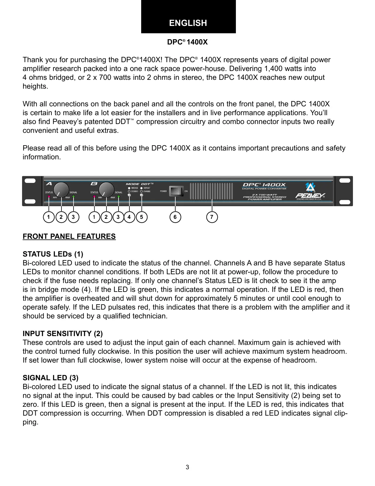
A STATUS MIN SIGNAL B STATUS MIN SIGNAL MODE DOT™ BRIDGE DEEAT STEREO ENABLE POWER ON DPC® 1400X DIGITAL POWER CONVERTER 2 X 700 WATT PROFESSIONAL STEREO POWER AMPLIFIER PEAVY® DESIGNED AND MADE IN U.S.A. 1 2 3 1 2 3 4 5 6 7FRONT PANEL FEATURES
STATUS LEDs (1)
Bi-colored LED used to indicate the status of the channel. Channels A and B have separate Status LEDs to monitor channel conditions. If both LEDs are not lit at power-up, follow the procedure to check if the fuse needs replacing. If only one channel's Status LED is lit check to see it the amp is in bridge mode (4). If the LED is green, this indicates a normal operation. If the LED is red, then the amplifier is overheated and will shut down for approximately 5 minutes or until cool enough to operate safely. If the LED pulsates red, this indicates that there is a problem with the amplifier and it should be serviced by a qualified technician.
INPUT SENSITIVITY (2)
These controls are used to adjust the input gain of each channel. Maximum gain is achieved with the control turned fully clockwise. In this position the user will achieve maximum system headroom. If set lower than full clockwise, lower system noise will occur at the expense of headroom.
SIGNAL LED (3)
Bi-colored LED used to indicate the signal status of a channel. If the LED is not lit, this indicates no signal at the input. This could be caused by bad cables or the Input Sensitivity (2) being set to zero. If this LED is green, then a signal is present at the input. If the LED is red, this indicates that DDT compression is occurring. When DDT compression is disabled a red LED indicates signal clipping.
MODE SWITCH (4)
This switch is used to change operational modes of the amplifier. When the switch is pressed in, the unit is placed in bridge mode (bridge mode is explained later in this manual) and uses only the Channel A input. When the switch is out, the amplifier operates in stereo mode utilizing both inputs. Accidental selection of bridge mode from stereo mode while the unit is in operation could cause severe damage to loudspeakers, particularly biamped systems.
DDT SWITCH (5)
This switch is used to enable or defeat the internal DDT ^™ compression circuitry. Normally the DDT function should be enabled to minimize the possibility of either or both channels going into clipping or overload. With DDT defeated, a severe overload could cause the mains fuse to blow as a matter of course. (DDT is covered in greater detail later in this manual.)
POWER SWITCH (6)
This switch is used to apply power to the unit, thus turning the unit on. Use the status indicators (1) to verify the actual power condition of the amp.
COOLING VENTS (7)
These vents provide a path for airflow. Since the DPC 1400X is a fan cooled device, it is very important not to cover these vents or obstruct the flow of air in any way.
BACK PANEL FEATURES
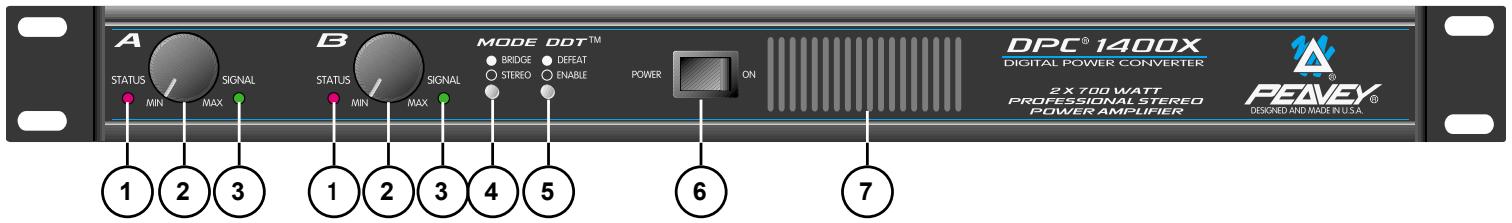
text_image
CLASS 1 WIRING SPEAKER JACKS PARALLELED 2 OHMS MIN. LOAD OUTPUTS SPEAKER JACKS PARALLELED 2 OHMS MIN. LOAD OUTPUTS DPC® 120 VAC 60 Hz 1700 WATTS 1400X FUSE 1.5 AMP A PRODUCT OF PEAVEY ELECTRONICS CORP. MERIDIAN, MS MADE IN U.S.A. B THRU INPUT THRU A 7 12 13 8 9 8 9CHANNEL INPUT (8)
This input features a combo connector that will accept a standard three-pin male XLR, 1/4" TRS (Tip-Ring-Sleeve), or 1/4" mono plug. An electronically balanced input is available via XLR and 1/4" TRS use. The unit is internally wired for the following:
| Input | XLR | TRS |
| (+) | Pin 2 | Tip |
| (-) | Pin 3 | Ring |
| GND | Pin 1 | Sleeve |
Unbalanced input is achieved by use of a 1/4" mono plug (patch cable). It is best to keep the cable from the output device to the input of the DPC 1400X as short as possible during unbalanced operation.
INPUT THRU (9)
This TRS 1/4" jack is used to daisy chain the inputs of the DPC 1400X to the inputs of other power amps or devices. Once again, short patch cables are highly recommended to minimize hum.
BINDING POST SPEAKER OUTPUTS (10)
Because of their high current handling capabilities, the binding post is recommended over the standard 1/4" connector. For this reason, one set of binding posts is provided for each channel of the the
DPC 1400X. The binding posts of each channel are wired in parallel with that channel's 1/4" outputs. This allows for parallel speaker systems. The minimum impedance in stereo mode is 2 ohms. Use of the amplifier below the minimum 2 ohm rating could result in overheating and thermal shutdown. In bridge mode connect the banana plug of your speaker cable to the red binding posts of channels A and B. The red binding post of channel A is the positive output terminal and the minimum load impedance is increased to 4 ohms while in bridge mode. (Bridge mode is explained in more detail later in this manual.)

PARALLEL 1/4" SPEAKER OUTPUTS (11)
Two parallel 1/4" speaker output jacks are provided for each channel of the DPC 1400X.
When adding speakers in parallel always keep in mind your total speaker impedance, insuring that it does not drop below the minimum load impedance rating of the DPC 1400X.

FUSE (12)
The fuse is located in the cap of the fuse holder. If the fuse should fail, IT MUST BE REPLACED WITH THE SAME TYPE AND VALUE IN ORDER TO AVOID DAMAGE TO TO EQUIPMENT AND TO PREVENT VOIDING THE WARRANTY. If the amp repeatedly blows fuses, it should be taken to a qualified service center for repair.

WARNING: THE FUSE SHOULD ONLY BE REPLACED WHEN THE POWER CORD HAS DISCONNECTED FROM ITS POWER SOURCE.
AC LINE CORD SOCKET (13)
Provided to accept the removable (IEC) type AC line cord. Connect only to proper source (see back panel markings.)
INSTALLATION AND CONNECTION
The DPC professional series of power amplifiers is designed for durability in commercial installations and has the quality of performance required in studio. These units are a standard rack-mount configuration height, and each is cooled by a variable-speed internal fan. All input and output connections are on the back panel. Additionally, the level controls and selector switches are on the front panel. The front panel also contains LED indicators for power and DDT activation, and the mains power switch.
INDUSTRIAL AND COMMERCIAL INSTALLATIONS
For commercial and other installations where sustained high power operation is required, the amplifiers should be mounted in a standard 19" rack. It is not necessary to leave a rack space between each amplifier in the stack since each fan pulls air in from the rear and exhausts the hot air out the front. However, an adequate cool air supply must be provided for the amplifier when rack-mounted. The internal fan must have a source of air that is not preheated by other equipment. If cool, the amplifier will start up in low speed fan operation and will normally stay at low speed operation unless sustained high power operating levels occur. Then, as the amplifier heat sinks heat up, the automatic thermal sensing circuitry will increase the fan speed. Depending upon signal conditions and amp loading, the fan speed may increase to a maximum value, or it may decrease to a minimum value. This situation is quite normal. If cooling is inadequate due to preheated air or a reduction of air flow occurs due to blockage of the amplifier inlet/outlet ports, or if the amplifier is severely overloaded or short circuited, the amplifier thermal sensing system may cause temporary shutdown of the unit. This is indicated by the status LEDs on the front panel illuminating red. Depending upon the available cooling air, operation should be restored relatively quickly, and the
status LEDs will be illuminated green. In any event, corrective action should be taken to determine the cause of the thermal shutdown. If the amplifier is not severely overloaded or shorted and air flow is normal in and out of the amplifier, then steps should be taken to provide a cooler environment for all the amplifiers. As a general rule, the cooler electronic equipment is operated, the longer its useful service life.
STUDIO AND FACILITY INSTALLATION
In most low to medium power applications, the power amplifier can be mounted in any configuration. It is desirable that, if at all possible, the power amplifier be located at the top of an equipment stack. This will prevent possible overheating of sensitive equipment by the hot air rising from the power amplifier. As a general rule, most studio requirements will never cause high speed fan operation. However, if they do, this may indicate that you have not taken the necessary steps to provide adequate cooling. Remember, closed up in a cabinet, a DPC Series power amplifier will have severe cooling problems, even at low power levels. Again, inadvertent short circuit or sustained overload usage could also cause temporary thermal shutdown and/or blowing of the fuse. Also, most home wiring and electrical circuits are only 15 amps.
BRIDGE MODE
The bridge mode on stereo amplifiers is often misunderstood as to the actual operation and usage. In basic terms, when a two-channel amplifier is operated in the bridge mode, it is converted into a single-channel unit with a power rating equal to the sum of both channels' power ratings at a Load Rating of twice that of the single channel rating. For example, the DPC 1400X is rated at 700 watts RMS per channel into 2 ohms. The bridge ratings are 1,400 watts RMS into 4 ohms (minimum load). Bridge mode operation is accomplished by placing the mode switch in the "BRIDGE" position, connecting the positive speaker lead to Channel A red binding post, negative speaker lead to Channel B red binding post, and using Channel A as the input channel. All Channel B input functions are defeated, and they serve no purpose now. Another common use for the bridge mode is in subwoofer applications where very high power levels are required to reproduce extreme low frequencies. Such enclosures usually contain 2 or 4 loudspeakers to handle the power levels involved. For bridge mode usage, the enclosure impedance must be 4 or 8 ohms—never below 4 ohms!
DDT™
Peavey's patented DDT (Distortion Detection Technique) compression circuit enables the user to maximize the performance of the amplifier/speaker combination by preventing the power amp from running out of headroom (clipping). This compression system is activated by a very unique circuit that senses signal conditions which might overload the amplifier and activates compression (reduces the amp gain) when clipping is imminent. Threshold of compression, then, is clipping itself, and no specific threshold control is used. This technique effectively utilizes every precious watt available for the power amplifier to reproduce the signal, while at the same time minimizing clipping and distortion and thus significantly reducing the potential of loudspeaker degradation and damage. The DDT system is an automatic hands-off approach to the problem of power amplifier clipping. Since the DPC Series power amplifiers use a fuse for “over current” protection, the DDT compression system plays even a more important role in continuous performance by preventing each channel from clipping and overload. Continuous operation at clipping can cause the fuse to blow, but with the DDT activated, this problem is minimized. For this reason, you should always have the DDT compression system enabled.
DPC® 1400X SPECIFICATIONS
Output Power: (typical value, 120 V AC, 60 Hz):
Stereo mode, both channels driven
2 ohms, 1,000 W power channel peak music power
4 ohms, 700 W power channel peak music power
8 ohms, 500 W power channel peak music power
Bridge mode
4 ohms, 2,000 W power peak music power
8 ohms, 1,400 W power peak music power
Rated Output Power (120 V AC, 60 Hz):
Stereo mode, both channels driven
2 ohms, 1 kHz, 700 W RMS per channel
4 ohms, 1 kHz, 525 W RMS per channel
8 ohms, 1 kHz, 325 W RMS per channel
Bridge mode
4 ohms, 1 kHz, 1,400 W RMS
8 ohms, 1 kHz, 1,000 W RMS
Power Bandwidth:
Stereo mode, both channels driven
4 ohms, 10 Hz to 20 kHz
Total Harmonic Distortion:
Stereo mode, both channels driven
1 kHz, 4 ohms rated output, less than 0.1%
Hum and Noise:
Stereo mode, both channels driven
Below rated output power 4 ohms, greater than
95 dB (A-weighted)
Damping Factor:
Stereo mode, both channels driven
4 ohms, 100 Hz, greater than 500
Input Sensitivity:
Input attenuator set @ FCW @ rated output power,
4 ohms, 1.4 V RMS (+3 dBV)
Input Impedance:
10k ohms unbalanced
Channel Voltage Gain:
Input attenuator set @ FCW
Stereo mode, 4 ohms, 1 kHz, 30 dB
Bridge mode, 8 ohms, 1 kHz, 39 dB
Frequency Response:
Stereo mode, both channels driven
+0.5, -3 dB, 1 W RMS, 4 ohms, 3 Hz to 25 kHz
The frequency response is internally controlled to optimize phase linearity and improve transient response.
Slew Rate:
The slew rate is internally controlled by a Bessel filter to optimize phase linearity and improve transient response. Because of this circuitry, the amplifier cannot slew rate limit.
Power Consumption:
Stereo mode, both channels driven @ rated output
power, 4 ohms 10 A @ 120 V AC
Cooling System:
Continuously variable speed DC blower
DDT™ Compression System:
Automatic, switchable with LED indicator
Dimensions and Height:
• Height 1.75" (4.4 cm)
- Width 19" (48.3 cm)
- Depth 16.5" (41.9 cm)
• Weight 15 lbs. (6.8 kg)
Specifications subject to change without notice.
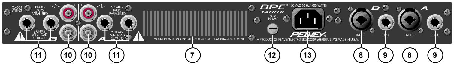
DPC® 1400X Hookup Diagram
text_image
Main Monitor Out In EQ™ 215FX SRC™ 4034 Main Input Monitor Input CLASS 1 WIRING SPEAKER JACKS PARALLELED 2 OHMS MIN. LOAD OUTPUTS B A 2 OHMS MIN. LOAD OUTPUTS A DPC® 120 VAC 60 Hz 1700 WATTS FUSE 15 AMP PEAVEY® A PRODUCT OF PEAVEY ELECTRONICS CORP. MERIDIAN, MS MADE IN U.S.A. INPUT THRU INPUT THRU Main Output Monitor Output SP™112M Impulse™ 200FRANÇAIS
DPC® 1400X
4 ohms, 1 kHz, 1,400 W RMS
8 ohms, 1 kHz, 1,000 W RMS
Bande passante:
Mode Stéréo, 4 ohms, 1 kHz, 30 dB
Mode Bridge, 8 ohms, 1 kHz, 39 dB
8 Ohm, 1 kHz, 325 W RMS pro Kanal
Bridge Mode
4 Ohm, 1 kHz, 1,400 W RMS
8 Ohm, 1 kHz, 1,000 W RMS
Total Harmonic Distortion:
Stereo Mode, 4 Ohm, 1 kHz, 30 dB
Bridge Mode, 8 Ohm, 1 kHz, 39 dB
Frequenzgang:
PEAVEY ELECTRONICS CORPORATION (“PEAVEY”) warrants this product, EXCEPT for covers, footswitches, patchcords, tubes and meters, to be free from defects in material and workmanship for a period of one (1) year from date of purchase, PROVIDED, however, that this limited warranty is extended only to the original retail purchaser and is subject to the conditions, exclusions, and limitations hereinafter set forth:
PEAVEY 90-DAY LIMITED WARRANTY ON TUBES AND METERS
If this product contains tubes or meters, Peavey warrants the tubes or meters contained in the product to be free from defects in material and workmanship for a period of ninety (90) days from date of purchase; PROVIDED, however, that this limited warranty is extended only to the original retail purchaser and is also subject to the conditions, exclusions, and limitations hereinafter set forth.
CONDITIONS, EXCLUSIONS, AND LIMITATIONS OF LIMITED WARRANTIES
These limited warranties shall be void and of no effect, if:
a. The first purchase of the product is for the purpose of resale; or
b. The original retail purchase is not made from an AUTHORIZED PEAVEY DEALER; or
c. The product has been damaged by accident or unreasonable use, neglect, improper service or maintenance, or other causes not arising out of defects in material or workmanship; or
d. The serial number affixed to the product is altered, defaced, or removed.
In the event of a defect in material and/or workmanship covered by this limited warranty, Peavey will:
a. In the case of tubes or meters, replace the defective component without charge.
b. In other covered cases (i.e., cases involving anything other than covers, footswitches, patchcords, tubes or meters), repair the defect in material or workmanship or replace
the product, at Peavey's option; and provided, however, that, in any case, all costs of shipping, if necessary, are paid by you, the purchaser.
THE WARRANTY REGISTRATION CARD SHOULD BE ACCURATELY COMPLETED AND MAILED TO AND RECEIVED BY PEAVEY WITHIN FOURTEEN (14) DAYS FROM THE DATE OF YOUR PURCHASE.
In order to obtain service under these warranties, you must:
a. Bring the defective item to any PEAVEY AUTHORIZED DEALER or AUTHORIZED PEAVEY SERVICE CENTER and present therewith the ORIGINAL
PROOF OF PURCHASE supplied to you by the AUTHORIZED PEAVEY DEALER in connection with your purchase from him of this product
If the DEALER or SERVICE CENTER is unable to provide the necessary warranty service you will be directed to the nearest other PEAVEY AUTHORIZED
DEALER or AUTHORIZED PEAVEY SERVICE CENTER which can provide such service, OR
b. Ship the defective item, prepaid, to:
PEAVEY ELECTRONICS CORPORATION
International Service Center
326 Hwy. 11 & 80 East
Meridian, MS 39301
Including therewith a complete, detailed description of the problem, together with a legible copy of the original PROOF OF PURCHASE and a complete return address. Upon Peavey's receipt of these items: If the defect is remedial under these limited warranties and the other terms and conditions expressed herein have been complied with, Peavey will provide the necessary warranty service to repair or replace the product and will return it, FREIGHT COLLECT, to you, the purchaser.
Peavey's liability to the purchaser for damages from any cause whatsoever and regardless of the form of action, including negligence, is limited to the actual damages up to the greater of \$500.00 or an amount equal to the purchase price of the product that caused the damage or that is the subject of or is directly related to the cause of action Such purchase price will be that in effect for the specific product when the cause of action arose. This limitation of liability will not apply to claims for personal injury or damage to real property or tangible personal property allegedly caused by Peavey's negligence, Peavey does not assume liability for personal injury or property damage arising out of or caused by a non-Peavey alteration or attachment, nor does Peavey assume any responsibility for damage to interconnected non-Peavey equipment that may result from the normal functioning and maintenance of the Peavey equipment.
UNDER NO CIRCUMSTANCES WILL PEAVEY BE LIABLE FOR ANY LOST PROFITS, LOST SAVINGS, ANY INCIDENTAL DAMAGES, OR ANY CONSEQUENTIAL DAMAGES ARISING OUT OF THE USE OR INABILITY TO USE THE PRODUCT, EVEN IF PEAVEY HAS BEEN ADVISED OF THE POSSIBILITY OF SUCH DAMAGES.
THESE LIMITED WARRANTIES ARE IN LIEU OF ANY AND ALL WARRANTIES, EXPRESSED OR IMPLIED, INCLUDING, BUT NOT LIMITED TO, THE IMPLIED WARRANTIES OF MERCHANTABILITY AND FITNESS FOR A PARTICULAR USE: PROVIDED, HOWEVER, THAT IF THE OTHER TERMS AND CONDITIONS NECESSARY TO THE EXISTENCE OF THE EXPRESSED, LIMITED WARRANTIES, AS HEREINABOVE STATED, HAVE BEEN COMPLIED WITH, IMPLIED
WARRANTIES ARE NOT DISCLAIMED DURING THE APPLICABLE ONE-YEAR OR NINETY-DAY PERIOD FROM DATE OF PURCHASE OF THIS PRODUCT.
SOME STATES DO NOT ALLOW LIMITATION ON HOW LONG AN IMPLIED WARRANTY LASTS, OR THE EXCLUSION OR LIMITATION OF INCIDENTAL OR CONSEQUENTIAL DAMAGES, SO THE ABOVE LIMITATIONS OR EXCLUSIONS MAY NOT APPLY TO YOU. THESE LIMITED WARRANTIES GIVE YOU SPECIFIC LEGAL RIGHTS, AND YOU MAY ALSO HAVE OTHER RIGHTS WHICH MAY VARY FROM STATE TO STATE.
THESE LIMITED WARRANTIES ARE THE ONLY EXPRESSED WARRANTIES ON THIS PRODUCT, AND NO OTHER STATEMENT, REPRESENTATION, WARRANTY, OR AGREEMENT BY ANY PERSON SHALL BE VALID OR BINDING UPON PEAVEY.
In the event of any modification or disclaimer of expressed or implied warranties, or any limitation of remedies, contained herein conflicts with applicable law, then such modification, disclaimer or limitation, as the case may be, shall be deemed to be modified to the extent necessary to comply with such law.
Your remedies for breach of these warranties are limited to those remedies provided herein and Peavey Electronics Corporation gives this limited warranty only with respect to equipment purchased in the United States of America.
INSTRUCTIONS—WARRANTY REGISTRATION CARD
- Mail the completed WARRANTY REGISTRATION CARD to:
PEAVEY ELECTRONICS CORPORATION
P.O. BOX 2898
Meridian, MS 39302-2898
a. Keep the PROOF OF PURCHASE In the event warranty service is required during the warranty period, you will need this document. There will be no identification card issued by Peavey Electronics Corporation
2. IMPORTANCE OF WARRANTY REGISTRATION CARDS AND NOTIFICATION OF CHANGES OF ADDRESSES:
a. Completion and mailing of WARRANTY REGISTRATION CARDS—Should notification become necessary for any condition that may require correction the REGISTRATION CARD will help ensure that you are contacted and properly notified.
b. Notice of address changes - If you move from the address shown on the WARRANTY REGISTRATION CARD, you should notify Peavey of the change of address so as to facilitate your receipt of any bulletins or other forms of notification which may become necessary in connection with any condition that may require dissemination of information or correction.
3. You may contact Peavey directly by telephoning (601) 483-5365.
IMPORTANT SAFETY INSTRUCTIONS
WARNING: When using electric products, basic cautions should always be followed. including the following.
- Read all safety and operating instructions before using this product.
- All safety and operating instructions should be retained for future reference.
- Obey all cautions in the operating instructions and on the back of the unit.
- All operating instructions should be followed.
- This product should not be used near water, i.e., a bathtub, sink, swimming pool, wet basement, etc.
- This product should be located so that its position does not interfere with its proper ventilation. It should not be placed flat against a wall or placed in a built-in enclosure that will impede the flow of cooling air.
- This product should not be placed near a source of heat such as a stove, radiator, or another heat producing amplifier.
- Connect only to a power supply of the type marked on the unit adjacent to the power supply cord.
- Never break off the ground pin on the power supply cord. For more information on grounding, write for our free booklet "Shock Hazard and Grounding."
- Power supply cords should always be handled carefully. Never walk or place equipment on power supply cords. Periodically check cords for cuts or signs of stress, especially at the plug and the point where the cord exits the unit.
11 The power supply cord should be unplugged when the unit is to be unused for long periods of time. - If this product is to be mounted in an equipment rack, rear support should be provided.
- Metal parts can be cleaned with a damp rag. The vinyl covering used on some units can be cleaned with a damp rag or an ammonia-based household cleaner if necessary. Disconnect unit from power supply before cleaning.
- Care should be taken so that objects do not fall and liquids are not spilled into the unit through the ventilation holes or any other openings.
- This unit should be checked by a qualified service technician if:
a. The power supply cord or plug has been damaged.
b. Anything has fallen or been spilled into the unit.
c. The unit does not operate correctly.
d. The unit has been dropped or the enclosure damaged.
- The user should not attempt to service this equipment. All service work should]d be done by a qualified service technician.
- This product should be used only with a cart or stand that is recommended by Peavey Electronics.
- Exposure to extremely high noise levels may cause a permanent hearing loss. individuals vary considerably in susceptibility to noise induced hearing loss, but nearly everyone will lose some hearing if exposed to sufficiently intense noise for a sufficient time. The U.S. Government's Occupational Safety and Health Administration (OSHA) has specified the following permissible noise level exposures.
| Duration Per Day In Hours | Sound Level dBA, Slow Response |
| 8 | 90 |
| 6 | 92 |
| 4 | 95 |
| 3 | 97 |
| 2 | 100 |
| 1 1/2 | 102 |
| 1 | 105 |
| 1/2 | 110 |
| 1/4 or less | 115 |
According to OSHA, any exposure in excess of the above permissible limits could result in some hearing loss. Ear plugs or protectors h1 the ear canal]s or over the ears must be worn when operating this amplification system in order to prevent a permanent hearing loss if exposure is in excess of the limits as set forth above. To ensure against potentially dangerous exposure to high Sound pressure levels. it is recommended that all persons exposed to equipment capable of producing high sound pressure levels such as this amplification system be protected by hearing protectors while this unit is in operation.
SAVE THESE INSTRUCTIONS!

PEAVEY®
Features and Specifications subject to change without notice
A Product of Peavey Electronic Corporation
711 A Street / Meridian, MS 39301 / U.S.A. / (601) 483-5365 / Fax (601) 486-1278