
PV 2000 - Power amplifier PEAVEY - Free user manual and instructions
Find the device manual for free PV 2000 PEAVEY in PDF.
User questions about PV 2000 PEAVEY
0 question about this device. Answer the ones you know or ask your own.
Ask a new question about this device
Download the instructions for your Power amplifier in PDF format for free! Find your manual PV 2000 - PEAVEY and take your electronic device back in hand. On this page are published all the documents necessary for the use of your device. PV 2000 by PEAVEY.
USER MANUAL PV 2000 PEAVEY
Intended to alert the user to the presence of uninsulated “dangerous voltage” within the product’s enclosure that may be of sufficient magnitude to constitute a risk of electric shock to persons.
A
Intended to alert the user of the presence of important operating and maintenance (servicing) instructions in the literature accompanying the product.
CAUTION: Risk of electrical shock – DO NOT OPEN!
CAUTION: To reduce the risk of electric shock, do not remove cover. No user serviceable parts inside. Refer servicing to qualified service personnel.
WARNING: To prevent electrical shock or fire hazard, do not expose this appliance to rain or moisture. Before using this appliance, read the operating guide for further warnings.
A
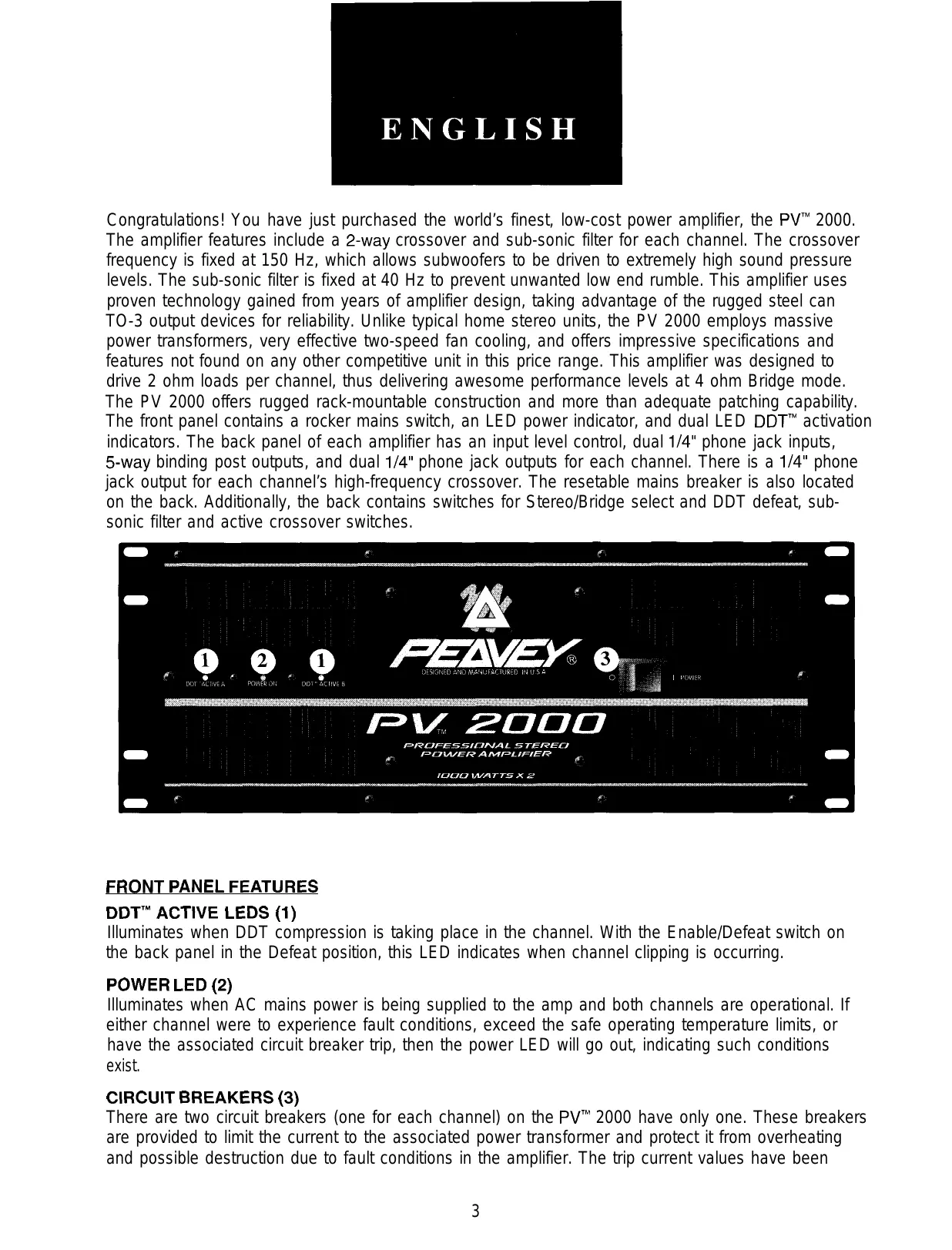
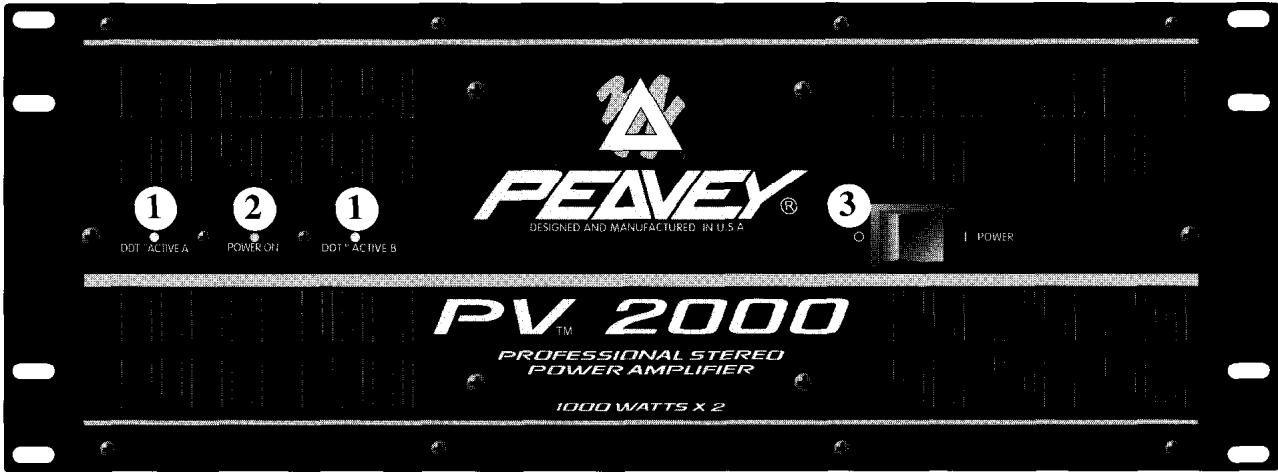
Congratulations! You have just purchased the world's finest, low-cost power amplifier, the PV™ 2000. The amplifier features include a 2-way crossover and sub-sonic filter for each channel. The crossover frequency is fixed at 150 Hz, which allows subwoofers to be driven to extremely high sound pressure levels. The sub-sonic filter is fixed at 40 Hz to prevent unwanted low end rumble. This amplifier uses proven technology gained from years of amplifier design, taking advantage of the rugged steel can TO-3 output devices for reliability. Unlike typical home stereo units, the PV 2000 employs massive power transformers, very effective two-speed fan cooling, and offers impressive specifications and features not found on any other competitive unit in this price range. This amplifier was designed to drive 2 ohm loads per channel, thus delivering awesome performance levels at 4 ohm Bridge mode. The PV 2000 offers rugged rack-mountable construction and more than adequate patching capability. The front panel contains a rocker mains switch, an LED power indicator, and dual LED DDT™ activation indicators. The back panel of each amplifier has an input level control, dual 1/4" phone jack inputs, 5-way binding post outputs, and dual 1/4" phone jack outputs for each channel. There is a 1/4" phone jack output for each channel's high-frequency crossover. The resetable mains breaker is also located on the back. Additionally, the back contains switches for Stereo/Bridge select and DDT defeat, sub-sonic filter and active crossover switches.
text_image
PEAVEY® DESIGNED AND MANUFACTURED IN U.S.A. 1 DOT ACTIVE A 2 POWER ON 1 DOT ACTIVE B 3 POWER PV TM 2000 PROFESSIONAL STEREO POWER AMPLIFIER 1000 WATTS X 2FRONT PANEL FEATURES
DDT™ ACTIVE LEDS (1)
Illuminates when DDT compression is taking place in the channel. With the Enable/Defeat switch on the back panel in the Defeat position, this LED indicates when channel clipping is occurring.
POWER LED (2)
Illuminates when AC mains power is being supplied to the amp and both channels are operational. If either channel were to experience fault conditions, exceed the safe operating temperature limits, or have the associated circuit breaker trip, then the power LED will go out, indicating such conditions exist.
CIRCUIT BREAKERS (3)
There are two circuit breakers (one for each channel) on the PV ^™ 2000 have only one. These breakers are provided to limit the current to the associated power transformer and protect it from overheating and possible destruction due to fault conditions in the amplifier. The trip current values have been
carefully chosen to allow continuous power output performance while still protecting the power transformer. Normally, these breakers should not trip unless there is a fault in the amplifier circuitry that draws excessive mains current. However, abnormal conditions such as a short circuit on either or both channels, or continuous operation at overload or clipping (especially into 2 ohm loads) will cause the breaker to trip. If this occurs, turn the power switch off, then simply reset the breaker and correct the cause of the overload.

When tripped, the button on the breaker will be outward nearly 1/2" and can be reset by pushing inward. A normal reset button length is about 1/4". If this "thermal" type breaker does trip, simply pushing the button back in will reset it, after waiting a brief period of time to allow it to cool down. REMEMBER, ALWAYS TURN THE POWER OFF BEFORE RESETTING THE BREAKER. If the breaker trips instantly each time you attempt to reset it, the unit should be taken to a qualified service center for repair.
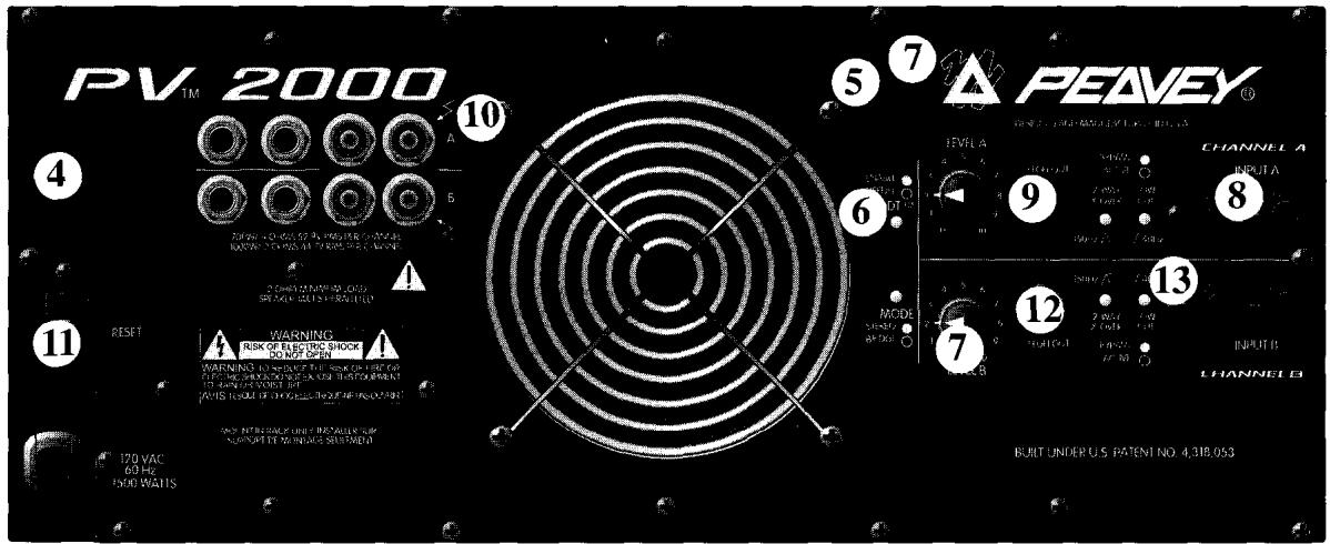
Back Panel
text_image
PV TM 2000 ④ 10 ⑤ ⑦ PEAVEY® LEVEL A CHANNEL A INPUT A ⑥ ⑧ ⑨ ⑩ MODE RANGE OFFICE MODE CHANNEL INPUT B CHANNEL B RESET WARNING 1 RISK OF ELECTRIC SHOCK DO NOT OPEN WARNING: WARNING ON MODE OR CHECK OR CHECK OR CHECK OR CHECK OR CHECK OR CHECK OR CHECK OR CHECK OR CHECK OR CHECK OR CHECK OR CHECK OR CHECK OR CHECK OR CHECK OR CHECK OR CHECK OR CHECK OR CHECK OR CHECK OR CHECK OR CHECK OR CHECK OR CHECK OR CHECK OR CHECK OR CHECK OR CHECK OR CHECK OR CHECK OR CHECK OR CHECK OR CHECK OR CHECK OR CHECK OR CHECK OR CHECK OR CHECK OR CHECK OR CHECK OR CHECK OR CHECK OR CHECK OR CHECK OR CHECK OR CHECK OR CHECK OR CHECK OR CHECK OR CHECK OR ACCESS 170 VAC 60 Hz 1500 WATTS MODE RANGE OFFICE MODE CHANNEL INPUT B CHANNEL B BUILT UNDER U.S. PATENT NO. 4,318,053BACK PANEL FEATURES
POWER SWITCH (4)
A heavy-duty, rocker-type switch. Selecting the "0" position turns off the power amplifier.
DDT SWITCH (5)
This switch is used to either Enable or Defeat the DDT compressor. Normally the DDT function should be enabled to minimize the possibility of either or both channels going into clipping or overload. With DDT defeated, a severe overload could cause the mains circuit breakers to trip as a matter of course. (The Peavey DDT compression system will be covered in greater detail later in this manual.)
MODE SWITCH (6)
This switch is used to select either Stereo or Bridge mode of operation. Care should be exercised whenever the Bridge mode is selected. Accidental selection of this mode could damage loudspeakers, particularly in biamped systems. (The Bridge mode will be covered in greater detail later in this manual.)
INPUT GAIN (7)
These controls are used to adjust the input gain of each channel. Thus, they determine how “loud” each channel of the power amplifier will “play” for a given input signal level. Maximum input gain (minimum sensitivity rating) is achieved at the full clockwise setting, and this setting yields maximum mixer/system headroom. A setting of less than full clockwise will yield lower system noise at the expense of mixer/system headroom.
HIGH-Z INPUT JACKS (8)
Two parallel 1/4" stereo input jacks are provided for each channel. This allows one to be used as a conventional input and, simultaneously, the other to be used as a "line out" (Y-cord) to connect to another input jack on this amplifier or other amps or equipment. These 1/4" jacks are not chassis grounded and will provide a unique ground loop elimination circuitry associated with each input. This feature will normally allow "hum-free" operation when relatively short 1/4" cable patches are made between the jacks on this amp and other jacks on various other equipment that share the same rack with this amp. The inputs are true electronically balanced to further eliminate any hum. A 1/4" stereo jack can be used at the input with the tip being the positive phase, the ring being the negative phase and the sleeve connected to ground. A mono 1/4" jack can also be used creating an unbalanced input.
HIGH OUT CROSSOVER JACKS (9)
These output jacks are provided for crossover capability. With the crossover switch depressed, the low-frequency signal is automatically routed to Channel A. The high-frequency signal has to be patched to the input of Channel B from this jack. If both channels are being used for the lows, (either Bridge mode or Stereo) then the HI OUT jacks can be connected to another amplifier to provide the highs in a 2-way system.
SPEAKER OUTPUTS (10)

Two 1/4" jacks and 5-way binding post speaker output terminals are provided for each channel. Again, for each channel, these outputs are in parallel; hence, the speaker connection cables can be terminated with 1/4" phone plugs, banana plugs, or stripped wires for use in the binding post terminals. For sustained high power applications, the use of the binding post terminals is recommended. However, care must be exercised to assure correct speaker phasing.
AC LINE CORD—120 V products only (11)

All the PV Series power amplifiers are fitted with a single, heavy-duty 3-conductor line cord and a conventional AC plug with a ground pin. It should be connected to an independent circuit capable of supporting at least 15 amps or greater continuously. This is particularly critical for sustained high power applications. If the socket used does not have a ground pin, a suitable ground lift adaptor should be used and the third wire grounded properly. Never break off the ground pin on any equipment. It is provided for your safety.
The use of extension cords should be avoided but, if necessary, always use a three-wire type with at least a #14 AWG wire size. The use of lighter wire will severely limit the power capability of this power amplifier. Always use a qualified electrician to install any new electrical equipment. To prevent the risk of shock or fire hazard, always be sure that the amplifier is properly grounded.
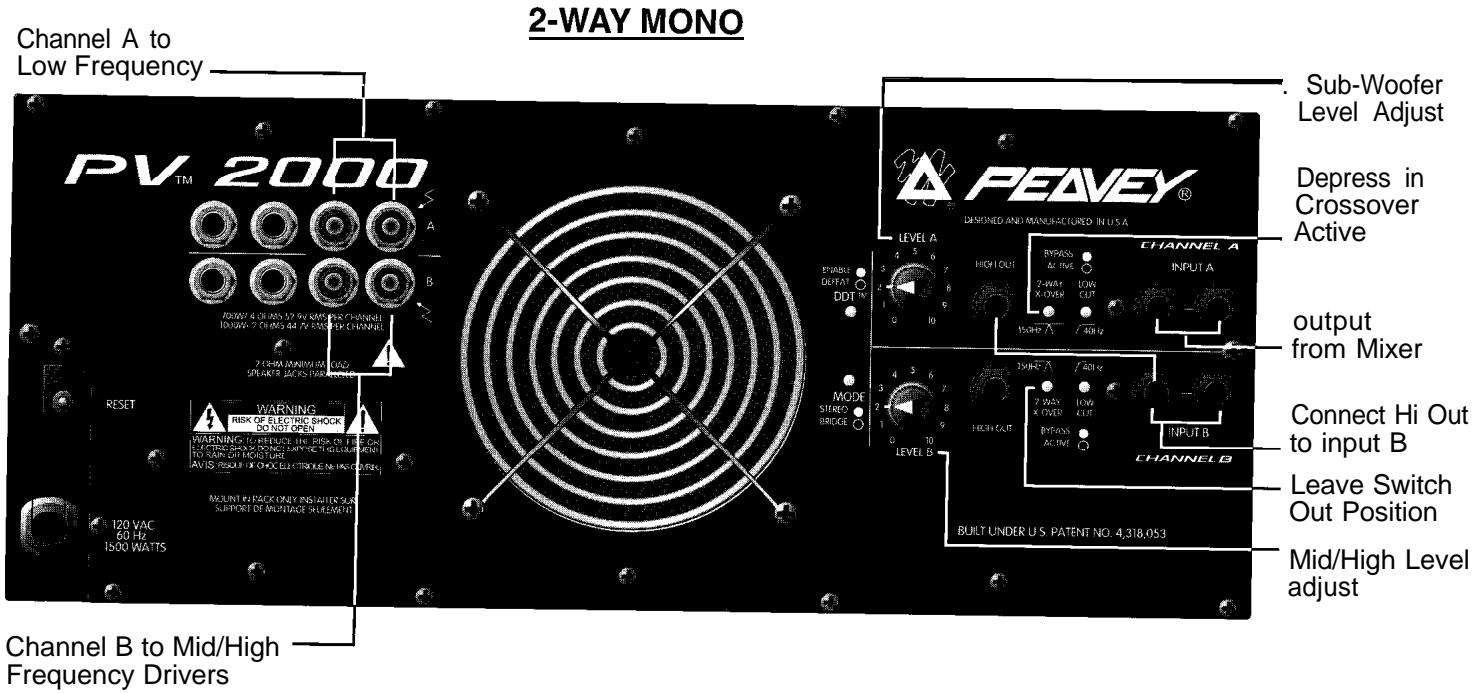
CROSSOVER SWITCH (12)
This switch is used to select the crossover capability of this amplifier. With this button depressed, the low frequencies are automatically sent to the corresponding channel. The high frequencies are sent to the HI OUT jack, which can be connected to either the other channel's input or another amplifier. The crossover frequency is fixed at 150 Hz.
SUB-SONIC FILTER (13)
Depressing this switch to the “in” position provides a 40 Hz high-pass filter for the corresponding channel. This will cut ultra-low frequencies, protecting speakers from the possibility of over-excursion. The low-frequency roll-off is 18 dB per octave.
INSTALLATION AND CONNECTION
The PV professional series of power amplifiers is designed for durability in commercial installations and has the quality of performance required in studio and home applications. These units are a standard rack-mount configuration height, and each is cooled by an automatic two-speed internal fan. All input and output connections are on the back panel. Additionally, the level controls, selector switches and the resetable circuit breakers are on the back panel. The front panel contains LED indicators for power and DDT activation and the main power switch.
INDUSTRIAL AND COMMERCIAL INSTALLATIONS
For commercial and other installations where sustained high power operation is required, the amplifiers should be mounted in a standard 19" rack. It is not necessary to leave a rack space between each amplifier in the stack since each fan pulls air in from the rear and exhausts the hot air out the front. However, an adequate 'COOL' air supply must be provided for the amplifier when rack-mounted. The internal fan must have a source of air that is not preheated by other equipment. The amplifier will start up in "low speed" fan operation and will normally stay at low speed operation unless sustained high power operating levels occur. Then, as the amplifier "heat sinks" heat up, the automatic thermal sensing circuitry will cause high speed operation to occur. Depending upon signal conditions and amp loading, high speed fan operation may continue or it may cycle continuously between high and low. This situation is quite normal. If cooling is inadequate due to preheated air, or a reduction of air flow occurs due to blockage of the amplifier inlet/outlet ports, or if the amplifier is severely overloaded or short circuited, the amplifier thermal sensing system may cause temporary shutdown of the unit. This is indicated by the power LED on the front panel ceasing to illuminate. Depending upon the available cooling air, operation should be restored relatively quickly, and the power LED will be illuminated. In any event, corrective action should be taken to determine the cause of the thermal shutdown. If the amplifier is not severely overloaded or shorted and air flow is normal in and out of the amplifier, then steps should be taken to provide a cooler environment for all the amplifiers. As a general rule, the cooler electronic equipment is operated, the longer its useful service life.
STUDIO AND HOME INSTALLATION
In most low to medium power applications, the power amplifier can be mounted in any configuration. It is desirable that, if at all possible, the power amplifier be located at the top of an equipment stack. This will prevent possible overheating of sensitive equipment by the hot air rising from the power amplifier. As a general rule, most home and studio requirements will never cause high speed fan operation. However, if it does, this may indicate that you have not taken the necessary steps to provide adequate cooling. Remember, closed up in a cabinet, a PV Series power amplifier will have severe cooling problems, even at low power levels. Again, inadvertent short circuit or sustained overload usage could also cause temporary thermal shutdown and/or tripping of the mains power breaker. Also, most home wiring and electrical circuits are only 15 amps. One PV 2000 can cause a 15 AMP breaker to trip if a severe overload occurs.
BRIDGE MODE
The actual operation and usage of the Bridge mode on stereo amplifiers is often misunderstood. In basic terms, when a two-channel amplifier is operated in the Bridge mode, it is converted into a single channel unit with a Power Rating equal to the sum of both channels' power ratings at a Load Rating of twice that of the single channel rating. For example, the PV 2000 is rated at 1000 watts RMS per channel into 2 ohms. The Bridge Ratings are 2000 watts RMS into 4 ohms (minimum load). Bridge mode operation is accomplished by placing the mode switch in the "BRIDGE" position, connecting the positive speaker lead to Channel A red binding post, negative speaker lead to Channel B red binding post, and using Channel A as the input channel. All Channel B input functions are defeated, and they serve no purpose now. Another application for Bridge mode operation is to drive sound distribution systems in very large public address applications. In this mode, any of the PV Series power amplifiers can actually drive 70 volt systems directly without using matching transformers. The real advantage of such an approach is primarily cost. 70 volt distribution systems are very common in domestic applications where large numbers of relatively small loudspeakers are used for background music and paging. Such systems require the use of 70 volt transformers at each loudspeaker. Another common use for the Bridge mode is in subwoofer applications where very high power levels are required to reproduce extreme low frequencies. Such enclosures usually contain 2 or 4 loudspeakers to handle the power levels involved. For Bridge mode usage, the enclosure impedance must be 4 or 8 ohms-never below 4 ohms!
DDT
Peavey's patented DDT (Distortion Detection Technique) compression circuit enables the sound technician to maximize the performance of the amplifier/speaker combination by preventing the power amp from running out of headroom (clipping). This compression system is activated by a unique circuit that senses signal conditions which might overload the amplifier and activates compression (reduces the amp gain) when clipping is imminent. Threshold of compression, then, is clipping itself, and no specific threshold control is used. This technique effectively utilizes every precious watt available for the power amplifier to reproduce the signal while at the same time minimizing clipping and distortion and thus significantly reducing the potential of loudspeaker degradation and damage. The DDT system is an automatic hands-off approach to the problem of power amplifier clipping. Since the PV Series power amplifiers use circuit breakers for “over current” protection, the DDT compression system plays even a more important role in continuous performance by preventing each channel from clipping and overload. Continuous operation at clipping can cause the circuit breakers to trip, but with the DDT activated, this problem is minimized. For this reason, you should always have the DDT compression system enabled.
SPECIFICATIONS
Output Power ^2,3 :
2 ohms, 1 kHz, 1% THD
4 ohms, 1 kHz, 1% THD
8 ohms, 1 kHz, 1% THD
Bridge mode, mono
4 ohms, 1 kHz, 1% THD
8 ohms, 1 kHz, 1% THD
Rated Output Power ^2 :
4 ohms, 20 Hz to 20 kHz, 1% THD
8 ohms, 20 Hz to 20 kHz, 0.1% THD
Slew Rate ^3 :
Stereo mode, each channel
Bridge mode, mono
Total Harmonic Distortion ^2,3 :
20 Hz to 20 kHz, @ rated output power, 8 ohms
Input Sensitivity & Impedance?
@ rated output power, 8 ohms
Dimensions &Weight:
Height
Width
Depth
Weight
Frequency Response ^2,3 :
±1dB, 1 W RMS, 8 ohms
f0.2 dB, @ rated output, 8 ohms
Damping Factor ^2,3 :
8 ohms, 1 kHz
Below rated output power, 8 ohms
Power Consumption?
@ rated output power, 8 ohms
Cooling System:
DDT Compression System:
PV-2000
1000 W RMS per channel
700 W RMS per channel
400 W RMS per channel
2000 W RMS
1400 W RMS
625 W RMS per channel
370 W RMS per channel
20 Volts per μSec
40 Volts per Sec
Less than 0.07%
1.0 V RMS (0 dBV)
20 K ohms (34 dB gain)
7" (17.8 cm)
19" (48.3 cm)
15" (38.2 cm)
55 lbs. (25.0 kg)
10 Hz to 40 kHz
20 Hz to 20 kHz
Greater than 300
100 dB, unweighted
12.7 A @ 120 VAC
2-speed fan
Switchable with LED
^1 @ 120 VAC, 60 Hz ^2 Stereo mode, both channels driven ^3 Typical Value ^4 Input attenuator set FCW
A
Due to our efforts for constant improvements,
features and specifications listed herein are subject to change without notice.
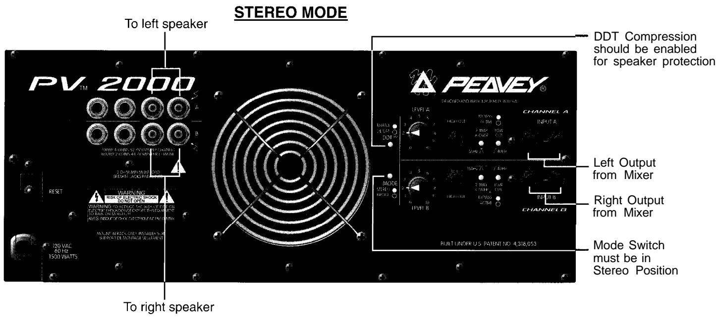
text_image
STEREO MODE To left speaker PV TM 2000 WARNING: A DDT, 52% PV (R4) (R1) (R2) (R3) (R4) (R5) (R6) (R7) (R8) (R9) (R10) (R11) RESET WARNING: RISK OF ELECTRIC SHOCK WARNING: TO REVE FOR AIR SKE SYSTEM OR SELECTING INVOICE ON PULSE ON FRONT ON PLANS ON SWITCH ON AVIS GROUP ON ELECTRONIC ON NETWORK MOUNT INJECTS ON SWITCH ON SWITCH ON SURFACE ON SWITCH ON SWITCH ON SWITCH ON 120 VAC 60 Hz 1500 WATTS To right speaker DDT Compression should be enabled for speaker protection PEAVEY® DINTEGRATED MAIN LEMONED SWITCH LEVEL A CHANNEL A INPUT A LEVEL B CHANNEL B MODE STRECH PICKER LEVEL C CHANNEL C LEVEL D CHANNEL D LEVEL E CHANNEL E CHANNEL F LEVEL G CHANNEL G CHANNEL H LEVEL I CHANNEL I CHANNEL J CHANNEL K CHANNEL L CHANNEL M CHANNEL N CHANNEL O CHANNEL P CHANNEL Q CHANNEL R CHANNEL S CHANNEL T CHANNEL U CHANNEL V CHANNEL W CHANNEL X CHANNEL Y CHANNEL Z CHANNEL Z CHANNEL Z CHANNEL Z CHANNEL Z CHANNEL Z CHANNEL Z CHANNEL Z CHANNEL Z CHANNEL Z CHANNEL Z CHANNEL Z CHANNEL Z CHANNEL Z CHANNEL Z CHANNEL Z CHANNEL Z CHANNEL Z CHANNEL Z CHANNEL Z CHANNEL Z CHANNEL Z CHANNEL Z CHANNEL Z CHANNEL Z CHANNEL Z CHANNEL Z CHANNEL Z CHANNEL Z CHANNEL Z CHANNEL Z CHANNEL Z CHANNEL Z CHANNEL Z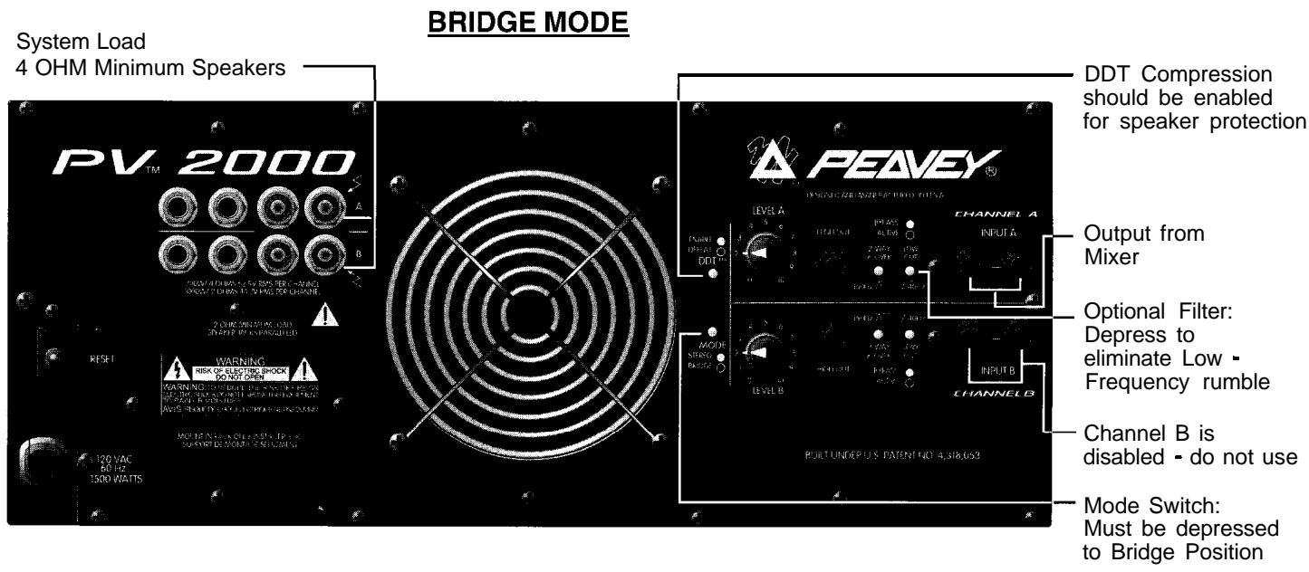
text_image
System Load 4 OHM Minimum Speakers BRIDGE MODE PV 2000 A B DOW AT BING AS FOR RISC PER CHAWING RICH OF CHAWING AS IN RISC PER CHAWING O DOW AT BING AS FOR CHAWING WARNING WARNING 120 VAC 50 Hz 1500 WATTS OUTPUT FROM MIXER OPTIONAL FILTER: DEPRESS TO ELIMATE LOW - FREQUENCY RUMBLE CHANNEL B CHANNEL A CHANNEL A CHANNEL B CHANNEL B CHANNEL B CHANNEL B CHANNEL B CHANNEL B CHANNEL B CHANNEL B CHANNEL B CHANNEL B CHANNEL B CHANNEL B CHANNEL B CHANNEL B CHANNEL B CHANNEL B CHANNEL B CHANNEL B CHANNEL B CHANNEL B CHANNEL B CHANNEL B CHANNEL B CHANNEL B CHANNEL B CHANNEL B CHANNEL B CHANNEL B CHANNEL B CHANNEL B CHANNEL B CHANNEL B CHANNEL B CHANNEL B| AWARNING!For optimum performance and reliability DO NOT PRESENT THE AMPLIFIER WITH A SPEAKER LOAD OF LESS THAN 2 OHMS, ORACOMBINATION OF SPEAKERS THAT TOGETHER ARE LESS THAN 2 OHMS!Using one speaker, it must be rated at 2 ohms minimum.Using two speakers, they must be rated each at 4 ohms minimum.Using three speakers, they must be rated each at 8 ohms minimum. | AAVIS!Pour assurer la Fiabilte et obtenitune performance optimale, ne soumette jamaisl'amplificateur a une charge d'impedance totale inferieurea 2 ohms, niavecun H P.ni en combinaison des H.P.AVEC un H.P., ilFautune charge d'impedance minimum de 2 ohms.AVEC deux H.P.,ilFaut pour chaounune charge d'impedance minimum de 4 ohmsAVEC trois H.P.,ilFaut pour chaounune charge d'impedance minimum de 8 ohms. |
text_image
Channel A to Low Frequency 2-WAY MONO PV TM 2000 RESSET 120 VAC 60 Hz 1500 WATTS Warning RISK OF ELECTRIC SHOCK DO NOT OPEN WARNING TO RECLUDE THE RISK ON LIME CH ELECTRIC SHOCK ONLY INSulator SAUC SUPPORT OF WLNTAGE SHELAMETER MODE STEREO BRIDGE 2 CHM MARGIN AS HIGH SPINJET PERIANCE 2 CHM MARGIN AS HIGH SPINJET PERIANCE PEAVEY® DESIGNED AND MANUFACTURED IN U.S.A. LEVEL A 4 5 6 HIGH OUT BYRASS AL TIME 2-WAT X-OVER LOW OUT 150Hz 40Hz CHANNEL A INPUT A OUTPUT from Mixer 3 MHz / 30Hz 2 WAT X-OVER LOW OUT BYRASS AL TIME INPUT B CHANNEL B Connect Hi Out to input B Leave Switch Out Position BUILT UNDER U.S. PATENT NO. 4,318,053 Sub-Woofer Level Adjust Depress in Crossover Active Channel B to Mid/High Frequency Drivers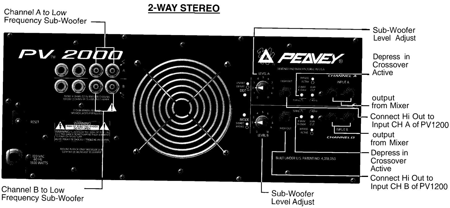
text_image
Channel A to Low Frequency Sub-Woofer 2-WAY STEREO PV TM 2000 A B WARNING 1:30 VAC 60 Hz 1500 WATTS RESET RISK OF ELECTRIC SHOCK DO NOT OPEN WARNING TO RESET THE RISK OF THIS EFFECTING SHOW ONLY EXPOSED THIS EQUIPMENT 120 VAC FOR HAND LINES AVIS FROM THE CHICKED ITEMS NE HAND LINES AMOUNT FOR PACK ONLY INSTALLERS IN SUPPORT BE NO NHASE SETTING Channel B to Low Frequency Sub-Woofer PEAVEY® DESIGNED AND MANUFACTURED BY USA LEVEL A 4 5 6 HIGH OUT 2 WAY LOW X GAIN CUT CHANNEL A INPUT A OUTPUT FROM MIXER Connect Hi Out to Input CH A of PV1200 OUTPUT FROM MIXER Connect Hi Out to Input CH B of PV1200 CHANNEL B BUILT UNDER U.S. PATENT NO. 4,318,053 Sub-Woofer Level Adjust Depress in Crossover Active Sub-Woofer Level Adjust Sub-Woofer Level AdjustESPAÑOL
PEAVEY ELECTRONICS CORPORATION (“PEAVEY”) warrants this product, EXCEPT for covers, footswitches, patchcords, tubes and meters, to be free from defects in material and workmanship for a period of one (1) year from date of purchase, PROVIDED, however, that this limited warranty is extended only to the original retail purchaser and is subject to the conditions, exclusions, and limitations hereinafter set forth:
PEAVEY 90-DAY LIMITED WARRANTY ON TUBES AND METERS
If this product contains tubes or meters, Peavey warrants the tubes or meters contained in the product to be free from defects in material and workmanship for a period of ninety (90) days from date of purchase; PROVIDED, however, that this limited warranty is extended only to the original retail purchaser and is also subject to the conditions, exclusions, and limitations hereinafter set forth.
CONDITIONS, EXCLUSIONS, AND LIMITATIONS OF LIMITED WARRANTIES
These limited warranties shall be void and of no effect, if:
a. The first purchase of the product is for the purpose of resale; or
b. The original retail purchase is not made from an AUTHORIZED PEAVEY DEALER; or
c. The product has been damaged by accident or unreasonable use, neglect, improper service or maintenance, or other causes not arising out of defects in material or workmanship; or
d. The serial number affixed to the product is altered, defaced, or removed.
In the event of a defect in material and/or workmanship covered by this limited warranty, Peavey will:
a. In the case of tubes or meters, replace the defective component without charge.
b. In other covered cases (i.e., cases involving anything other than covers, footswitches, patchcords, tubes or meters), repair the defect in material or workmanship or replace the product, at Peavey's option; and provided, however, that, in any case, all costs of shipping, if necessary, are paid by you, the purchaser.
THE WARRANTY REGISTRATION CARD SHOULD BE ACCURATELY COMPLETED AND MAILED TO AND RECEIVED BY PEAVEY WITHIN FOURTEEN (14) DAYS FROM THE DATE OF YOUR PURCHASE.
In order to obtain service under these warranties, you must:
a. Bring the defective item to any PEAVEY AUTHORIZED DEALER or AUTHORIZED PEAVEY SERVICE CENTER and present therewith the ORIGINAL
PROOF OF PURCHASE supplied to you by the AUTHORIZED PEAVEY DEALER in connection with your purchase from him of this product.
If the DEALER or SERVICE CENTER is unable to provide the necessary warranty service you will be directed to the nearest other PEAVEY AUTHORIZED DEALER or AUTHORIZED PEAVEY SERVICE CENTER which can provide such service.
OR
b. Ship the defective item, prepaid, to:
PEAVEY ELECTRONICS CORPORATION
International Service Center
326 Hwy. 11 & 80 East
Meridian, MS 39301
including therewith a complete, detailed description of the problem, together with a legible copy of the original PROOF OF PURCHASE and a complete return address. Upon Peavey's receipt of these items: If the defect is remedial under these limited warranties and the other terms and conditions expressed herein have been complied with, Peavey will provide the necessary warranty service to repair or replace the product and will return it, FREIGHT COLLECT, to you, the purchaser
Peavey's liability to the purchaser for damages from any cause whatsoever and regardless of the form of action, Including negligence, is limited to the actual damages up to the greater of \$500.00 or an amount equal to the purchase price of the product that caused the damage or that is the subject of or is directly related to the cause of action. Such purchase price will be that in effect for the specific product when the cause of action arose. This limitation of liability will not apply to claims for personal injury or damage to real property or tangible personal property allegedly caused by Peavey's negligence. Peavey does not assume liability for personal injury or property damage arising out of or caused by a non-Peavey alteration or attachment, nor does Peavey assume any responsibility for damage to Interconnected non-Peavey equipment that may result from the normal functioning and maintenance of the Peavey equipment.
UNDER NO CIRCUMSTANCES WILL PEAVEY BE LIABLE FOR ANY LOST PROFITS, LOST SAVINGS, ANY INCIDENTAL DAMAGES, OR ANY CONSEQUENTIAL DAMAGES ARISING OUT OF THE USE OR INABILITY TO USE THE PRODUCT, EVEN IF PEAVEY HAS BEEN ADVISED OF THE POSSIBILITY OF SUCH DAMAGES.
THESE LIMITED WARRANTIES ARE IN LIEU OF ANY AND ALL WARRANTIES, EXPRESSED OR IMPLIED, INCLUDING, BUT NOT LIMITED TO, THE IMPLIED WARRANTIES OF MERCHANTABILITY AND FITNESS FOR A PARTICULAR USE; PROVIDED, HOWEVER, THAT IF THE OTHER TERMS AND CONDITIONS NECESSARY TO THE EXISTENCE OF THE EXPRESSED, LIMITED WARRANTIES, AS HEREINABOVE STATED, HAVE BEEN COMPLIED WITH, IMPLIED WARRANTIES ARE NOT DISCLAIMED DURING THE APPLICABLE ONE-YEAR OR NINETY-DAY PERIOD FROM DATE OF PURCHASE OF THIS PRODUCT.
SOME STATES DO NOT ALLOW LIMITATION ON HOW LONG AN IMPLIED WARRANTY LASTS, OR THE EXCLUSION OR LIMITATION OF INCIDENTAL OR CONSEQUENTIAL DAMAGES, SO THE ABOVE LIMITATIONS OR EXCLUSIONS MAY NOT APPLY TO YOU. THESE LIMITED WARRANTIES GIVE YOU SPECIFIC LEGAL RIGHTS, AND YOU MAY ALSO HAVE OTHER RIGHTS WHICH MAY VARY FROM STATE TO STATE.
THESE LIMITED WARRANTIES ARE THE ONLY EXPRESSED WARRANTIES ON THIS PRODUCT, AND NO OTHER STATEMENT, REPRESENTATION, WARRANTY, OR AGREEMENT BY ANY PERSON SHALL BE VALID OR BINDING UPON PEAVEY.
In the event of any modification or disclaimer of expressed or implied warranties, or any limitation of remedies, contained herein conflicts with applicable law, then such modification, disclaimer or limitation, as the case may be, shall be deemed to be modified to the extent necessary to comply with such law.
Your remedies for breach of these warranties are limited to those remedies provided herein and Peavey Electronics Corporation gives this limited warranty only with respect to equipment purchased in the United States of America.
INSTRUCTIONS -WARRANTY REGISTRATION CARD
- Mail the completed WARRANTY-REGISTRATION CARD to:
PEAVEY ELECTRONICS CORPORATION
P.O. BOX 2898
Meridian, MS 39302-2898
a. Keep the PROOF OF PURCHASE. In the event warranty service is required during the warranty period, you will need this document. There will be no identification card issued by Peavey Electronics Corporation.
- IMPORTANCE OF WARRANTY REGISTRATION CARDS AND NOTIFICATION OF CHANGES OF ADDRESSES:
a. Completion and mailing of WARRANTY REGISTRATION CARDS — Should notification become necessary for any condition that may require correction, the REGISTRATION CARD will help ensure that you are contacted and properly notified.
b. Notice of address changes – If you move from the address shown on the WARRANTY REGISTRATION CARD, you should notify Peavey of the change of address so as to facilitate your receipt of any bulletins or other forms of notification which may become necessary in connection with any condition that may require dissemination of information or correction.
- You may contact Peavey directly by telephoning (601) 483-5365.
IMPORTANT SAFETY INSTRUCTIONS
WARNING: When using electric products, basic cautions should always be followed, including the following:
- Read all safety and operating instructions before using this product.
- All safety and operating instructions should be retained for future reference.
3 Obey all cautions in the operating instructions and on the back of the unit. - All operating instructions should be followed.
- This product should not be used near water, i.e., a bathtub, sink, swimming pool, wet basement, etc.
- This product should be located so that its position does not interfere with its proper ventilation. It should not be placed flat against a wall or placed in a built-in enclosure that will impede the flow of cooling air.
- This product should not be placed near a source of heat such as a stove, radiator, or another heat producing amplifier.
- Connect only to a power supply of the type marked on the unit adjacent to the power supply cord.
- Never break off the ground pin on the power supply cord. For more information on grounding, write for our free booklet “Shock Hazard and Grounding.”
- Power supply cords should always be handled carefully. Never walk or place equipment on power supply cords. Periodically check cords for cuts or signs of stress, especially at the plug and the point where the cord exits the unit.
1 I. The power supply cord should be unplugged when the unit is to be unused for long periods of time. - If this product is to be mounted in an equipment rack, rear support should be provided.
- Metal parts can be cleaned with a damp rag. The vinyl covering used on some units can be cleaned with a damp rag or an ammonia-based household cleaner if necessary. Disconnect unit from power supply before cleaning.
-
Care should be taken so that objects do not fall and liquids are not spilled into the unit through the ventilation holes or any other openings.
-
This unit should be checked by a qualified service technician if:
a. The power supply cord or plug has been damaged.
b. Anything has fallen or been spilled into the unit.
c. The unit does not operate correctly.
d. The unit has been dropped or the enclosure damaged.
-
The user should not attempt to service this equipment. All service work should be done by a qualified service technician.
-
This product should be used only with a cart or stand that is recommended by Peavey Electronics.
-
Exposure to extremely high noise levels may cause a permanent hearing loss. Individuals vary considerably in susceptibility to noise induced hearing loss, but nearly everyone will lose some hearing if exposed to sufficiently intense noise for a sufficient time. The U.S. Government's Occupational Safety and Health Administration (OSHA) has specified the following permissible noise level exposures.
| Duration Per Day In Hours | Sound Level dBA, Slow Response |
| 8 | 90 |
| 6 | 92 |
| 4 | 9.5 |
| 3 | 97 |
| 2 | 100 |
| I 1/2 | 102 |
| 1 | 105 |
| 1/2 | 110 |
| I/4 or less | 115 |
According to OSHA, any exposure in excess of the above permissible limits could result in some hearing loss.
Ear plugs or protectors in the ear canals or over the ears must be worn when operating this amplification system in order to prevent a permanent hearing loss if exposure is in excess of the limits as set forth above. To ensure against potentially dangerous exposure to high sound pressure levels, it is recommended that all persons exposed to equipment capable of producing high sound pressure levels such as this amplification system be protected by hearing protectors while this unit is in operation.
SAVE THESE INSTRUCTIONS!

text_image
Stylized logo with stylized text and registered trademark symbolFeatures and specifications subject to change without notice.

Peavey Electronics Corporation 711 A Street / Meridian, MS 39301 / U.S.A. / (601) 483-5365 / Fax 486-1278