
MM-8848 - Power amplifier PEAVEY - Free user manual and instructions
Find the device manual for free MM-8848 PEAVEY in PDF.
User questions about MM-8848 PEAVEY
0 question about this device. Answer the ones you know or ask your own.
Ask a new question about this device
Download the instructions for your Power amplifier in PDF format for free! Find your manual MM-8848 - PEAVEY and take your electronic device back in hand. On this page are published all the documents necessary for the use of your device. MM-8848 by PEAVEY.
USER MANUAL MM-8848 PEAVEY
Intended to alert the user to the presence of uninsulated "dangerous voltage" within the product's enclosure that may be of sufficient magnitude to constitute a risk of electric shock to persons.

Intended to alert the user of the presence of important operating and maintenance (servicing) instructions in the literature accompanying the product.
CAUTION: Risk of electrical shock - DO NOT OPEN!
CAUTION: To reduce the risk of electric shock, do not remove cover. No user serviceable parts inside. Refer servicing to qualified service personnel.
WARNING: To prevent electrical shock or fire hazard, do not expose this appliance to rain or moisture. Before using this appliance, read the operating guide for further warnings.

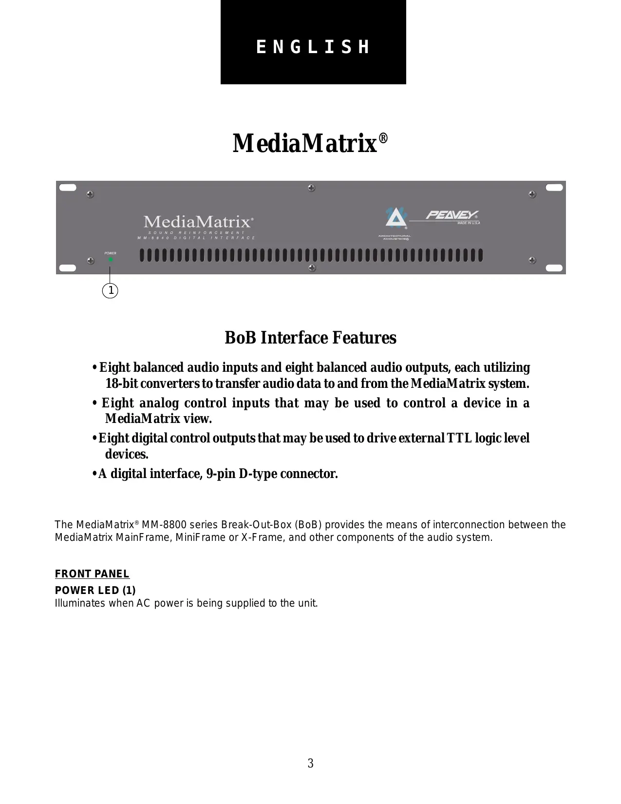
BoB Interface Features
- Eight balanced audio inputs and eight balanced audio outputs, each utilizing 18-bit converters to transfer audio data to and from the MediaMatrix system.
- Eight analog control inputs that may be used to control a device in a MediaMatrix view.
- Eight digital control outputs that may be used to drive external TTL logic level devices.
- A digital interface, 9-pin D-type connector.
The MediaMatrix® MM-8800 series Break-Out-Box (BoB) provides the means of interconnection between the MediaMatrix MainFrame, MiniFrame or X-Frame, and other components of the audio system.
FRONT PANEL
POWER LED (1)
Illuminates when AC power is being supplied to the unit.
Rear Panel:
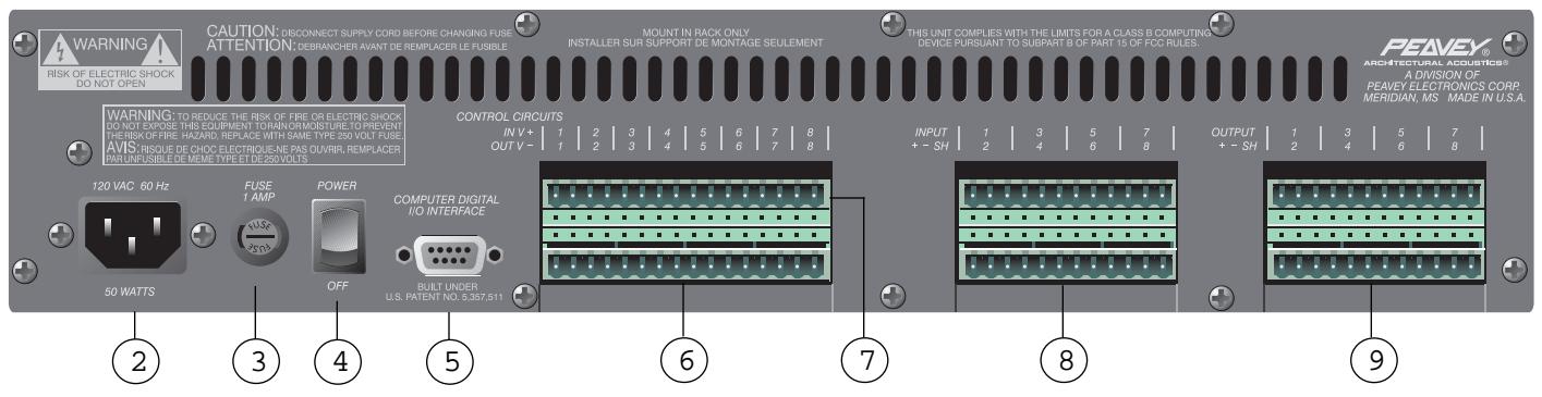
REAR PANEL
IEC LINE CORD INPUT (2)

Provided to accept the removable AC line cord.
FUSE (3)

WARNING: THE FUSE SHOULD ONLY BE REPLACED WHEN THE POWER CORD HAS BEEN DISCONNECTED FROM ITS POWER SOURCE.

CAUTION: USING A FUSE LARGER THAN THE RECOMMENDED SIZE COULD RESULT IN PERMANENT DAMAGE TO THE UNIT.
The fuse is located within the cap of the fuseholder. If the fuse should fail, IT MUST BE REPLACED WITH THE SAME TYPE AND VALUE IN ORDER TO AVOID DAMAGE TO THE EQUIPMENT AND TO PREVENT VOIDING THE WARRANTY. If the unit repeatedly blows fuses, it should be taken to a qualified service center for repair.
POWER SWITCH (4)
Switch to "On" position to turn on. The red LED will illuminate indicating power is being supplied to the unit.
COMPUTER DIGITAL I/O INTERFACE (5)
Connect the 9-pin D-type BoB cable here. This cable provides the link to the MediaMatrix system.
CONTROL CIRCUIT OUTPUTS (6)
These are TTL level outputs, switchable from within a MediaMatrix view. There are two electrical connections per channel; the right connection is the ground interface and the left connection is the TTL level output. See the Wiring Connections section for Control Output circuit examples.
CONTROL CIRCUIT INPUTS (7)
The inputs provide the means of controlling a device within a MediaMatrix view. There are two electrical connections per channel. See the Wiring Connections section for Control Input circuit examples.
AUDIO INPUTS (8)
Each of these eight channels is a balanced analog audio input to the MediaMatrix system. See the Wiring Connections section for Audio Input wiring examples.
AUDIO OUTPUTS (9)
Each of these eight channels is a balanced analog audio output from the MediaMatrix system. See the Wiring Connections section for Audio Output wiring examples.
SPECIFICATIONS
SYSTEM SPECIFICATIONS
Maximum Input Level:
+18 dBu or +24 dBu
Input Impedance:
Greater than 12K ohms for +18 dBu full scale
Greater than 15K ohms for +24 dBu full scale
Electronically Balanced
Maximum Output Level:
200 ohms, electronically balanced
Power Requirements:
Domestic: 120V AC, 60 Hz, 50W
Export: 230V AC, 50/60 Hz, 50W
Dimensions & Weight:
3.5" H x 19" W x 11.25" D (excluding connectors)
17 lbs.
Included Accessories:
IEC Line Cord
6' BoB Cable
(2) 16-position Phoenix-type connectors
(4) 12-position Phoenix-type connectors
ANALOG TO DIGITAL CONVERTER
MM-8830: 18-bit, 64x oversampled, 32 kHz sample rate
MM-8840: 18-bit, 64x oversampled, 44.1 kHz sample rate
MM-8848: 18-bit, 64x oversampled, 48 kHz sample rate
Frequency Response:
MM-8830: ±1.0 dB, 20 Hz to 16 kHz
MM-8840: ±0.5 dB, 20 Hz to 20 kHz
MM-8848: ±0.5 dB, 20 Hz to 20 kHz
Signal-to-Noise Ratio:
MM-8830: Greater than 96 dB
MM-8840: Greater than 98 dB
MM-8848: Greater than 100 dB
Crosstalk:
MM-8830: Greater than 95 dB
MM-8840: Greater than 95 dB
MM-8848: Greater than 97 dB
Total Harmonic Distortion:
MM-8830: Less than 0.01% at 1 kHz
MM-8840: Less than 0.01% at 1 kHz
MM-8848: Less than 0.01% at 1 kHz
DIGITAL TO ANALOG CONVERTER
MM-8830: 18-bit, 64x oversampled, 32 kHz sample rate
MM-8840: 18-bit, 64x oversampled, 44.1 kHz sample rate
MM-8848: 18-bit, 64x oversampled, 48 kHz sample rate
Frequency Response:
MM-8830: ±1.0 dB, 20 Hz to 16 kHz
MM-8840: ±0.5 dB, 20 Hz to 20 kHz
MM-8848: ±0.5 dB, 20 Hz to 20 kHz
Signal-to-Noise Ratio:
MM-8830: Greater than 92 dB
MM-8840: Greater than 95 dB
MM-8848: Greater than 96 dB
Crosstalk:
MM-8830: Greater than 91 dB
MM-8840: Greater than 94 dB
MM-8848: Greater than 95 dB
Total Harmonic Distortion:
MM-8830: Less than 0.01% at 1 kHz
MM-8840: Less than 0.01% at 1 kHz
MM-8848: Less than 0.01% at 1 kHz

Wiring Diagram
Control Input Examples
Input Sources:
- Linear example allows control of device by tracking pot linearly.
-
Nonlinear example allows control of device by tracking pot nonlinearly.
-
• Switch allows binary control of a device in a MediaMatrix view.
- Variable DC supply can be used to control device - NO MORE THAN 10V!
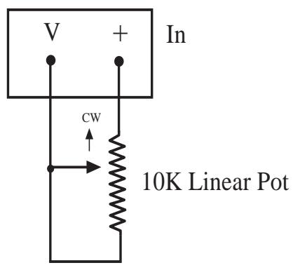
(1) Linear Example

(1) Nonlinear Example
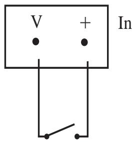
(2) Switch
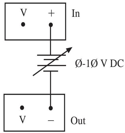
(3) DC Supply
Wiring Diagram
Control Output Examples
The eight control outputs appear on a separate Phoenix connector on the back of the Break-Out-Box. They provide logic outputs from the system. The output voltage is TTL format. Outputs are capable of sourcing 6ma and sinking 20ma while maintaining valid TTL levels. There are two electrical connections for each channel output control. When viewing the unit from the back, the left connection is the positive terminal. These outputs can be used to control devices as follows:
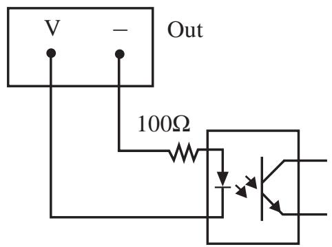
An Opto-Isolator:
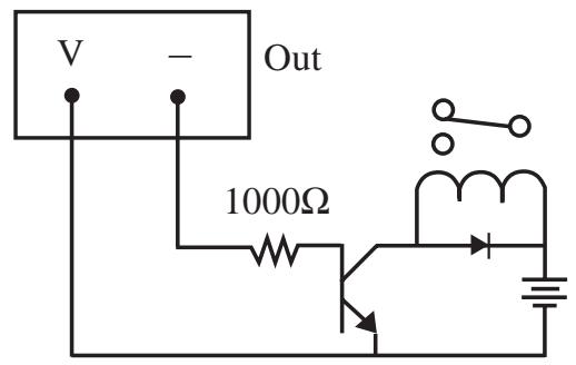
A Relay:

An LED:
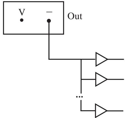
Up to 15 TTL Loads:
Wiring Diagram
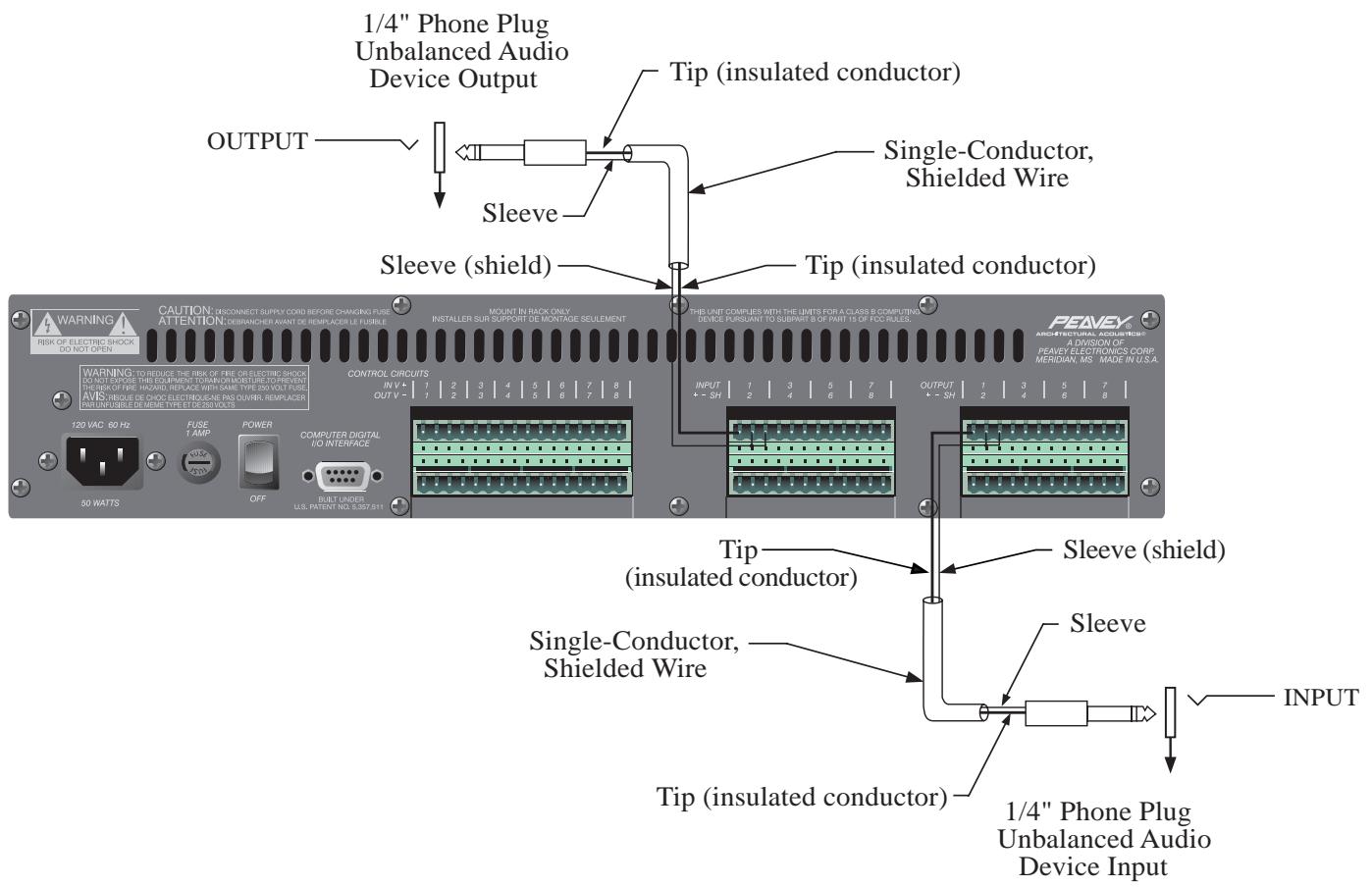
Using the Breakout Box with an Unbalanced Audio Device
- Unbalanced audio device output to balanced BoB input.
- Balanced BoB output to unbalanced audio device input.
Note: Be sure to ground the unused negative terminal on the BoB input/output.
Wiring Diagram
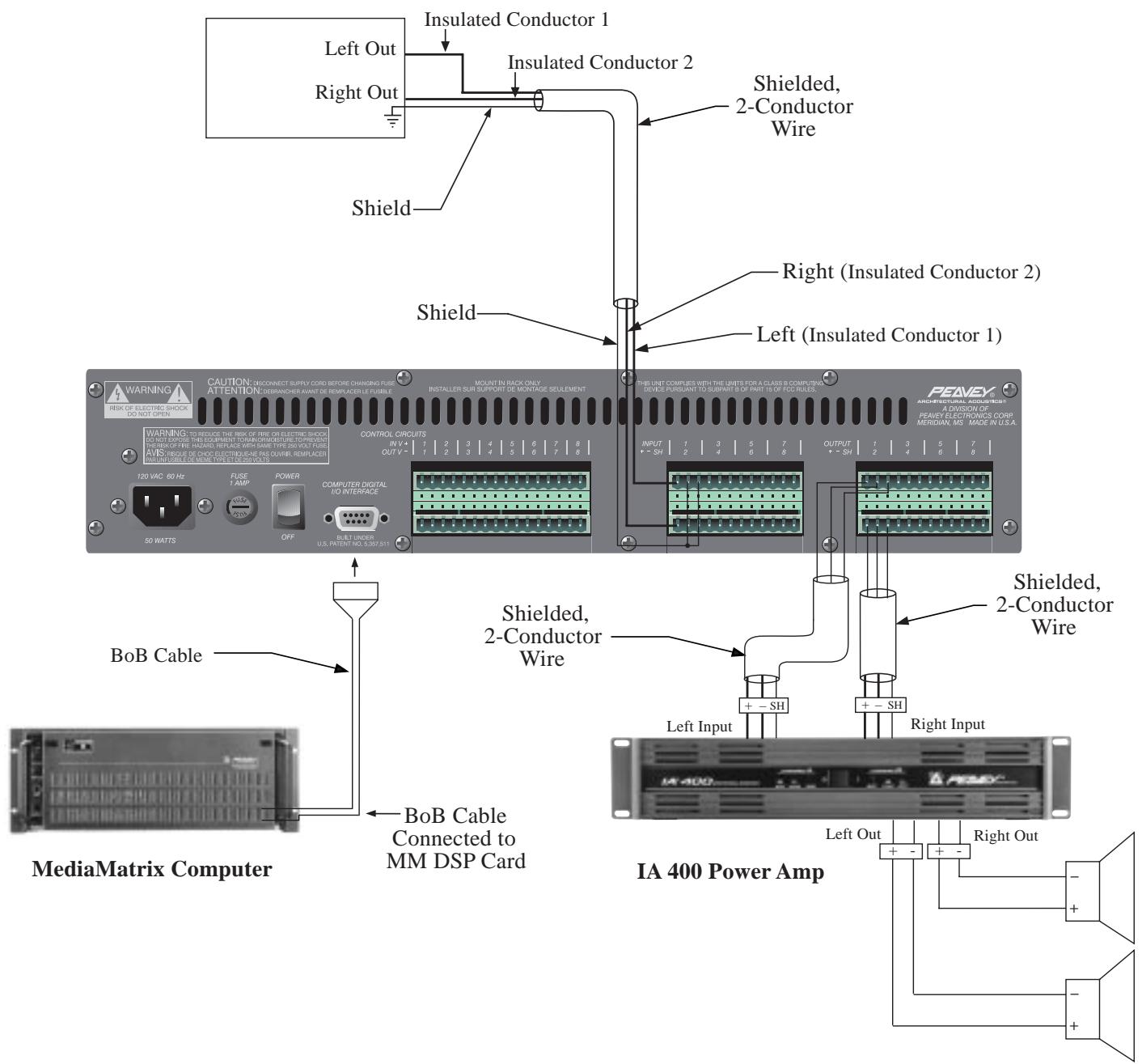
CD Player or Other Line Level Audio Device
Note: If using an unbalanced audio source, be sure to ground the unused negative inputs on the BoB.
Wiring Diagram
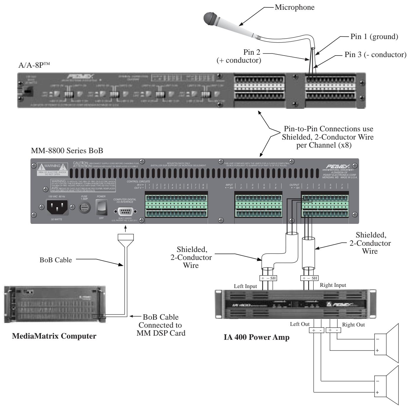
MediaMatrix System with Microphone Preamp
For further information on other Peavey Architectural Acoustics products, ask your Authorized Peavey Sound Contractor for the appropriate
Peavey Architectural Acoustics catalog/publication:
The BluePrint
Commercial Sound for Permanent Installations
Engineered Sound Products for Permanent Installations

Be Sure to Ask About Products in the Following Categories:
Modular Series Mixer, Mixer/Amplifiers
Rack Kits for MA™ Series Products
Wall Mount Mixer/Amplifiers
Non-powered Mixers
Powered Mixers
Equalizers-Analog
Equalizers-Programmable
Electronic Crossover/Delay Processors
Power Amplifiers
Loudspeaker Systems
Acoustical Components
Utility Amplifiers, Mixer/Amplifiers
Rack Kits for UMA™ Series Products
Telephone Paging
Zone Paging Systems
Mixers and Mixing Consoles
Power Amplifiers
Loudspeaker Systems
Microphones
LIMITED WARRANTY
Peavey Electronics Corporation warrants to the original purchaser of this new Architectural Acoustics product that it is free from defects in material and workmanship. If within one (1) year from date of purchase a properly installed product proves to be defective and Peavey is notified, Peavey will repair or replace it at no charge. (Note: Batteries and patch cords not covered.) "Original purchaser" means the customer for whom the product is originally installed.
Damage resulting from improper installation, interconnection of a unit or system of another manufacturer, accident or unreasonable use, neglect or any other cause not arising from defects in material and workmanship is not covered by this warranty. The warranty is valid only as to products purchased and installed in the United States and Canada.
THIS LIMITED WARRANTY IS IN LIEU OF ANY AND ALL WARRANTYES, EXPRESSED OR IMPLIED, INCLUDING THE IMPLIED WARRANTYES OF MERCHANTABILITY AND FITNESS FOR A PARTICULAR USE. UNDER NO CIRCUMSTANCES WILL PEAVEY BE LIABLE FOR ANY LOST PROFITS, LOST SAVINGS, INCIDENTTAL DAMAGES OR CONSEQUENTIAL DAMAGES ARISING OUT OF THE USE OR INABILITY TO USE THE PRODUCT, EVEN IF PEAVEY HAS BEEN ADVISED OF THE POSSIBILITY OF SUCH DAMAGE. THIS LIMITED WARRANTY IS THE ONLY EXPRESSED WARRANTY ON THIS PRODUCT, AND NO OTHER STATEMENT, REPRESENTATION, WARRANTY, OR AGREEMENT BY ANY PERSON SHALL BE VALID OR BINDING UPON PEAVEY.
Peavey's liability to the original purchaser for damages for any cause whatsoever and regardless of the form of action is limited to the actual damages up to the greater of Five Hundred Dollars ($500) or an amount equal to the purchase price of the product that caused the damage or that is the subject of or is directly related to the cause of action. This limitation of liability will not apply to claims for personal injury or damage to real property or tangible personal property allegedly caused by Peavey's negligence. For information on service under this warranty, call a Peavey customer service representative at (601) 483-5376.
IMPORTANT SAFETY INSTRUCTIONS
WARNING: When using electric products, basic cautions should always be followed, including the following.
- Read all safety and operating instructions before using this product.
- All safety and operating instructions should be retained for future reference.
- Obey all cautions in the operating instructions and on the back of the unit.
- All operating instructions should be followed.
- This product should not be used near water, i.e., a bathtub, sink, swimming pool, wet basement, etc.
- This product should be located so that its position does not interfere with its proper ventilation. It should not be placed flat against a wall or placed in a built-in enclosure that will impede the flow of cooling air.
- This product should not be placed near a source of heat such as a stove, radiator, or another heat producing amplifier.
- Connect only to a power supply of the type marked on the unit adjacent to the power supply cord.
- Never break off the ground pin on the power supply cord. For more information on grounding, write for our free booklet "Shock Hazard and Grounding."
- Power supply cords should always be handled carefully. Never walk or place equipment on power supply cords. Periodically check cords for cuts or signs of stress, especially at the plug and the point where the cord exits the unit.
- The power supply cord should be unplugged when the unit is to be unused for long periods of time.
- If this product is to be mounted in an equipment rack, rear support should be provided.
- Metal parts can be cleaned with a damp rag. The vinyl covering used on some units can be cleaned with a damp rag or an ammonia-based household cleaner if necessary. Disconnect unit from power supply before cleaning.
- Care should be taken so that objects do not fall and liquids are not spilled into the unit through the ventilation holes or any other openings.
- This unit should be checked by a qualified service technician if:
a. The power supply cord or plug has been damaged.
b. Anything has fallen or been spilled into the unit.
c. The unit does not operate correctly.
d. The unit has been dropped or the enclosure damaged.
- The user should not attempt to service this equipment. All service work should be done by a qualified service technician.
- This product should be used only with a cart or stand that is recommended by Peavey Electronics.
- Exposure to extremely high noise levels may cause a permanent hearing loss. Individuals vary considerably in susceptibility to noise induced hearing loss, but nearly everyone will lose some hearing if exposed to sufficiently intense noise for a sufficient time.
The U.S. Government's Occupational Safety and Health Administration (OSHA) has specified the following permissible noise level exposures.
| Duration Per Day In Hours | Sound Level dBA, Slow Response |
| 8 | 90 |
| 6 | 92 |
| 4 | 95 |
| 3 | 97 |
| 2 | 100 |
| 1 1/2 | 102 |
| 1 | 105 |
| 1/2 | 110 |
| 1/4 or less | 115 |
According to OSHA, any exposure in excess of the above permissible limits could result in some hearing loss.
Ear plugs or protectors in the ear canals or over the ears must be worn when operating this amplification system in order to prevent a permanent hearing loss if exposure is in excess of the limits as set forth above. To ensure against potentially dangerous exposure to high sound pressure levels, it is recommended that all persons exposed to equipment capable of producing high sound pressure levels such as this amplification system be protected by hearing protectors while this unit is in operation.
SAVE THESE INSTRUCTIONS!

Features and specifications subject to change without notice.
A Division of Peavey Electronics Corporation
711 A Street / Meridian, MS 39301 / U.S.A. / (601) 483-5376 / Fax (601) 486-1154
