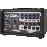
3D MIX PRO - Mixer PEAVEY - Free user manual and instructions
Find the device manual for free 3D MIX PRO PEAVEY in PDF.

| Product Type | 2-Channel DJ Mixer |
| Brand | PEAVEY |
| Model | 3D MIX PRO |
| Stereo Inputs | 2 inputs: CD/Line (RCA) and Phono/Line (RCA) with selector |
| Microphone Inputs | 2 balanced XLR inputs with +15V phantom power |
| Main Outputs | Balanced TRS (L/R), unbalanced RCA (L/R), Tape RCA (-10 dB), Booth Jack (L/R), Stereo headphone Jack, unbalanced Mono Jack |
| Effects Loop | Stereo TRS Jack (send+return) with Engage and Cue selectors |
| Channel Equalization | 3-band active: Hi (10 kHz), Mid (850 Hz), Low (70 Hz); boost +12 dB, cut -22 dB |
| Microphone Equalization | 2-band: Hi (10 kHz), Low (80 Hz); boost/cut ±15 dB; 75 Hz high-pass filter (18 dB/oct) |
| High-Pass Filter | 40 Hz filter (18 dB/oct) on main outputs |
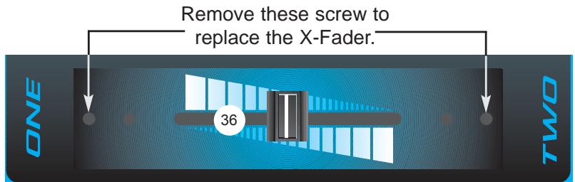
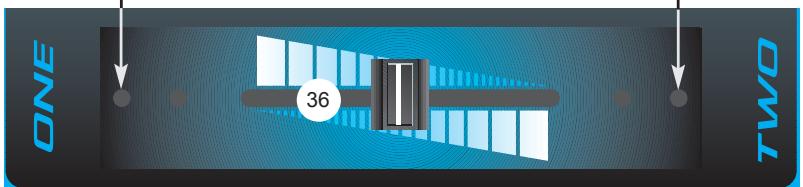
| Crossfader | 45 mm, replaceable by unscrewing |
| Channel Fader | 100 mm, stereo, max gain +10 dB |
| Spatial Expander | SRS® with width control and momentary Collapse button |
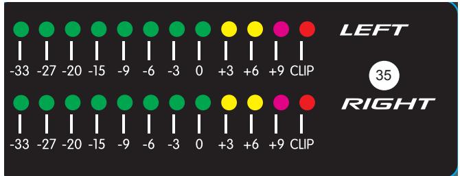
| VU Meter | 12-segment stereo LED, from -33 dB to clipping |
| LED Indicators | Signal, Cue, Mute, Power, Voice-Over, Loop, SRS |
| Voice-Over Function | Reduces music level by 10 dB for microphones |
| Headphones | Stereo Jack output with dedicated level; Normal/Split modes |
| Booth Output | Stereo Jack with independent level |
| Power Supply | IEC connector, mandatory grounding |
| Cleaning | Dry cloth only |
| Spare Parts | User-replaceable crossfader |
| Turntable Compatibility | Two ground terminals and Phono input with preamp |
Frequently Asked Questions - 3D MIX PRO PEAVEY
User questions about 3D MIX PRO PEAVEY
0 question about this device. Answer the ones you know or ask your own.
Ask a new question about this device
Download the instructions for your Mixer in PDF format for free! Find your manual 3D MIX PRO - PEAVEY and take your electronic device back in hand. On this page are published all the documents necessary for the use of your device. 3D MIX PRO by PEAVEY.
USER MANUAL 3D MIX PRO PEAVEY
Professional DJ Mixing Console
Operating Guide

Intended to alert the user to the presence of uninsulated "dangerous voltage" within the product's enclosure that may be of sufficient magnitude to constitute a risk of electric shock to persons.

Intended to alert the user of the presence of important operating and maintenance (servicing) instructions in the literature accompanying the product.
CAUTION: Risk of electrical shock — DO NOT OPEN!
CAUTION: To reduce the risk of electric shock, do not remove cover. No user serviceable parts inside. Refer servicing to qualified service personnel.
WARNING: To prevent electrical shock or fire hazard, do not expose this appliance to rain or moisture. Before using this appliance, read the operating guide for further warnings.

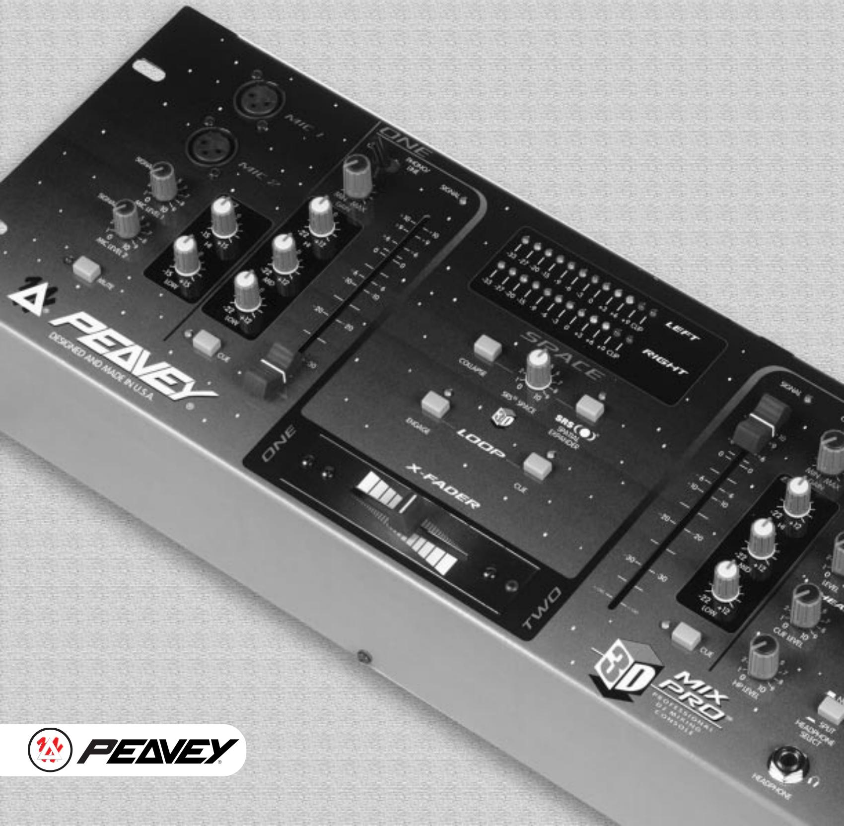
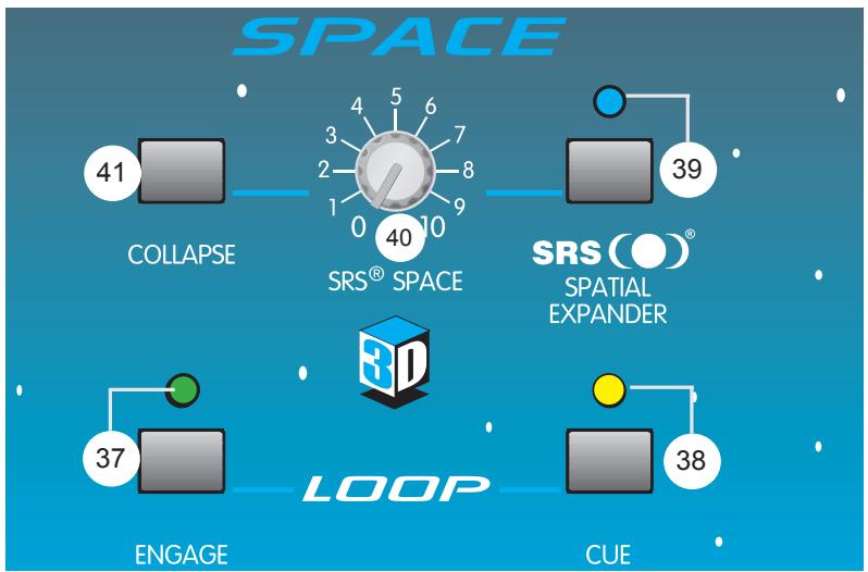
The 3D Mix Pro™ is a two channel, two-mic DJ mixer, with SRS® stereo enhancement circuitry to enlarge the space of the left-right stereo field. Each stereo channel has three-band equalization with 22 dB of cut and 12 dB of boost to allow for creative mixing of different frequency bands. A signal present LED and a cue switch are provided to check the signal.
The microphone inputs have individual level controls and signal present LEDs. They share a two band EQ, a 75 Hz low cut filter (non-defeatable), and a mute switch. Phantom power (15 V) is available to power condenser mics.
If external effects are desired, a music only loop function — enabled by a switch and monitored with its own cue switch — allows the insertion of external components such as delay, flange, or other special effects into the music signal path. Built into this path is the SRS system to give a greater depth to the stereo image. A special "collapse" switch toggles the signal from the width set by the SRS space control to mono, for dramatic spatial effects on the fly.
A cueing feature has been provided to check the status of Channels 1 and 2 and the loop return before they are routed to the main outputs. This signal drives the headphone and booth outputs. A headphone pan control and a split switch give the DJ other ways to compare cue and main signals.
In addition to the main servo-balanced (TRS) output, the 3D Mix Pro has unbalanced (phono) and tape (-10 dB) outputs. A third order, 40Hz rumble filter can be switched in to keep inaudible, power-robbing, low frequency energy from the speakers. A dual twelve segment LED display indicates the main output level. The 3D Mix Pro is powered by an internal power supply.
FEATURES
Two Distinct Stereo Input Channels:
Features per channel
Two selectable stereo inputs
One input selectable to phono or line (rear)
CD/Phono(Line) switch
100 mm smooth operating fader
Three-band active EQ with extreme 22 dB cut
Input gain trim control
Gold-plated RCA connectors
Cue switch w/LED
Signal present LED
Two Microphone Inputs: Features per input
XLR balanced input jack
Rotary level control
Signal present LED
15 V phantom power
Master mic features
Two-band EQ
Low cut filter (18 dB/oct @ 75 Hz)
Mute switch w/LED
Master Section:
Replaceable ultra smooth X-Fader (45 mm)
Main level
Main balance pan
Booth level
Mono level
Music (no mic) L/R 1/4" loop jacks (post X-Fader)
Loop in/out engage w/LED
Loop cue w/LED
Cue master level
Headphone level
HP selector switch (normal/split)
HP pan (cue/main)
SRS enable switch w/LED
SRS width control (space)
SRS collapse switch (momentary)
Manual voice-over switch w/LED
Main rumble filter (40 Hz) switch (rear)
Stereo 12 seg meters (-33 dB to clip range)
Headphone jack
Booth outputs (1/4")
Tape outputs (RCA)
Main L/R outputs (TRS balanced 1/4" and RCA)
Mono out (1/4" unbalanced)
Two turntable ground posts (rear)
Power switch — rear
Power on LED
IEC AC line input
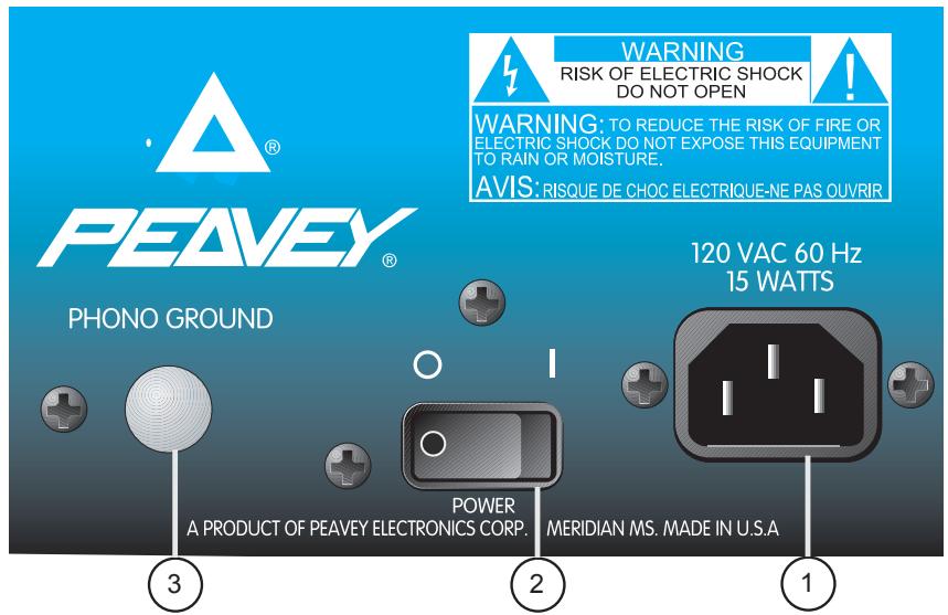
POWER AND GROUNDING
1. Removable AC Power Cord/IEC Socket
This receptacle is for the IEC line cord (included), which provides AC power to the unit. Connect the line cord to this connector and to a properly grounded AC supply. Damage to the equipment may occur if an improper line voltage is used. (See voltage marking on unit.) Never remove or cut the ground pin of the line cord plug. This unit is supplied with a properly rated line cord. When lost or damaged, replace this cord with one of the proper ratings.
2. Power Switch
This switch applies power to the unit. Press the switch to the (I) position to turn the unit on. Return the switch to the (O) position to turn it off. The Power LED (24) will illuminate when proper power is supplied to the 3D Mix Pro.
3. Phono Ground
Grounds from external turntables should be connected at this point. Note: There are two points on the rear of the unit for convenience.
MAIN OUTPUTS
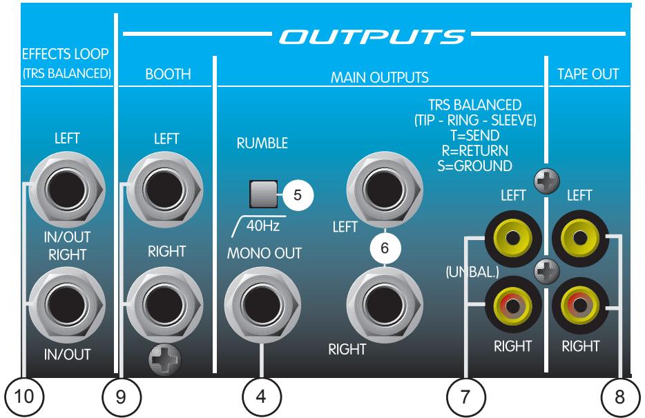
4. Mono Out
This 1/4" output supplies an unbalanced mono (L+R) signal to an outboard EQ, power amp, lighting system, or subwoofer crossover etc. The Mono Out level is set by the Mono Level control (29).
5. 40 Hz Rumble Switch
The Rumble Switch inserts a low cut filter at the main outputs, rolling the signal off at 40Hz . Use this switch to eliminate turntable rumble and excessive low frequency energy. Using the rumble switch in this manner will increase amplifier headroom.
6. Main TRS Balanced Outputs (L and R)
These 1/4" balanced stereo outputs are the preferred method of signal transfer from the 3D Mix Pro's main outputs to outboard equipment. The 1/4" connectors are Tip-Ring-Sleeve (TRS), where the tip is positive, the ring is negative, and the sleeve is ground. Use these Left and Right connectors for optimum power amp noise rejection. These outputs are also compatible with unbalanced (TS) inputs. The signals at this output are controlled by the Main Level control (26).
7. Main RCA Unbalanced Outputs (L and R)
These RCA (phono) stereo outputs are unbalanced and should be used when the TRS Balanced Outputs are not practical. You will achieve the same output signal here as with the TRS Balanced Outputs. The connectors are gold-plated for maximum life and minimal contact resistance.
MONITOR OUTPUTS
8. Tape Outputs (L and R)
The Tape Outputs are duplicates of the RCA Unbalanced Outputs except -10 dB lower in level. They offer a Left and Right output designed to feed a recording tape deck. These outputs also feature gold-plated connectors and may be used as an additional output to external line level gear.
9. Booth Outputs (L and R)
These 1/4" unbalanced stereo outputs are used to feed the booth (or monitor) amplifiers. They have the same signal as the headphones, but have their own level control. With the Headphone Select switch in the "Normal" position, the signal determined by the Headphone Pan control (31) will be present. In the "Split" mode, the left signal will be a sum of the L+R cue signals and the right signal will be a sum of the L+R main signals. This allows you to monitor the cue on the left and the main on the right. The Booth Output level is always controlled by the master Booth Level control (28).
EFFECTS SEND/RETURN
10. Effects Loop (L and R)
Stereo 1/4" TRS jacks are provided for use with external effects units such as delays, reversbs, exciters, etc. Both jacks (L and R) are wired so that the tip is the send and the ring is the return. Of course, the sleeve is a common ground. The Effects Loop is post X-Fader, meaning that the X-fader controls what is being sent to your effects. Signal is present at the Effects Loop sends at all times, so it can be cued but not applied to the mains until the Loop Engage button (37) is pressed. (The indicator light will illuminate.) Effects can be checked during a cue by pressing the Loop Cue switch (38).
INPUT CHANNELS 1 AND 2
The following section will cover information pertaining to the input channels. Since the 3D Mix Pro has two, identical, feature-packed channels, all descriptions in this section pertain to both channels. For ease of explanation, this section is divided into two subsections: INPUTS and CONTROLS/INDICATORS.
INPUTS
11. CD/Line Level Input
These gold-plated, stereo RCA jacks are provided for connection to external devices such as a CD, Minidisc, or DAT player. DO NOT USE THIS CONNECTION AS AN INPUT FOR TURNTABLES.
12. Phono/Line Level Input
This stereo input can be used for two types of equipment as determined by the Phono/Line switch (13). With the switch in Phono position, this input will accept the
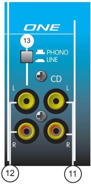
output from a turntable cartridge. By placing the switch in the Line position, you can adjust this input to handle line level signals from a CD, Minidisc, or DAT player. An improper setting can result in severe clipping and distortion.
13. Phono/Line
This switch changes the input gain and equalization of the Phono/Line Level Input (12) to accommodate either a Phono or Line level signal. With the switch in, the input is set for line level signals. In the up position, the switch sets the input for low level cartridge signals. This switch does not affect the CD/Line Level Input (11).

CAUTION: DO NOT CHANGE THE PHONO/LINE SWITCH FROM THE LINE POSITION TO THE
PHONO POSITION WHILE MATERIAL IS BEING PLAYED. A MAJOR CHANGE IN GAIN IS
INTRODUCED, WHICH WILL RAISE YOUR SIGNAL LEVEL DRASTICALLY. THIS COULD RESULT IN
DAMAGE TO BOTH HEARING AND EQUIPMENT.
CONTROLS/INDICATORS
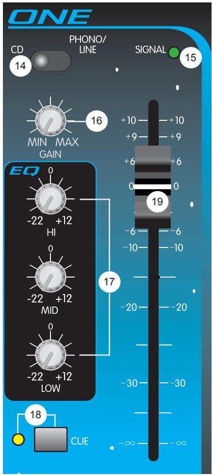
14. Input Selector
The Input Selector switch determines which stereo pair of RCA inputs will be present on the channel. In the CD position, the CD/Line Level Input (11) is utilized by the channel. When placed in the Phono/Line position, the channel uses the Phono/Line Level Input (12). This switch effectively gives you four inputs for connecting a variety of material sources.
15. Signal Present LED
This LED illuminates to indicate that a signal is present on the channel (prefader). Signals below the -20 dBu level will not illuminate the LED and need to be adjusted higher with the Gain (16) adjustment control.
16. Gain
The Gain control adjusts the input gain of the selected inputs. Use the Gain control to reduce strong signals and to amplify weaker signals. With the Channel Fader (19) set to 0 dB, adjust the gain control to a nominal output. The MIN position will produce no output and the MAX position will produce 6 dB of gain.
17. EQ
The EQ section consists of three active equalization controls: Hi, Mid, and Low. A shelving type filter is used for the Hi and Low, centered at 10 kHz and 70 Hz respectively. The Mid EQ is of the peaking type and is centered at 850 Hz. Each control offers a boost of up to +12 dB or a cut of up to -22 dB for creative mixing techniques.
18. Cue/Cue LED
This switch allows the channel's signal to be present in the Headphone and the Booth Outputs. In typical operation, only the Cue switch from one channel should be activated at any given time. While one channel is playing, the other is usually in cue. Thus, you should find yourself pressing these buttons simultaneously and quite often throughout a show. The Cue LED will illuminate when the cue is active for the channel.
19. Channel Fader
This 100 mm stereo fader offers a smooth transition from infinite cut to +10 dB of boost. Use this control after your input gain and EQ have been set. Use the Stereo Level Meters to monitor the level from the Channel Fader. The signal level determined by the Channel Fader should stay consistent when crossfading from channel to channel. In standard practice, this control is generally set to 0 dB for nominal output.
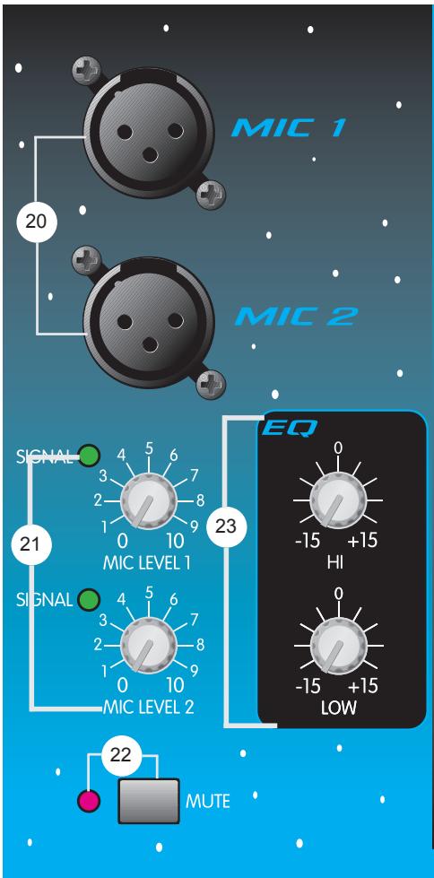
20. Mic 1/Mic 2 Inputs
Mic 1 and Mic 2 Inputs are balanced XLR types. Each has a separate Level control but shares a common EQ. A phantom power of +15 VDC is supplied automatically for those mics that may require it. Care should be taken when using some wireless mics that cannot work with phantom power. Consult your wireless mic owner's manual for proper operation. If phantom power cannot be used it is possible to modify your unit to defeat the phantom power. You may contact an authorized Peavey Service Center for more information.
21. Mic Signal Level/Indicator
The Mic 1 and Mic 2 Level controls adjust the input level of their respective mics. Turning the control fully clockwise (+45 dB) will result in maximum gain. Both level controls have a signal present LED Indicator which illuminates when the signal level exceeds -40 dBu.
22. Mute Switch/Indicator
The Mute Switch defeats both mics so that they become inactive when mic silence is desired. Mute is indicated when the Mute LED Indicator illuminates.
23. Mic EQ
This two-band (Hi and Low) active equalization affects only the Mic 1 and Mic 2 signals. The Hi EQ is centered at 10kHz and the Low at 80Hz . Both are of the shelving type and offer between 15 dB of gain and 15 dB of cut. Built into the EQ path is a 75 Hz 18 dB/oct low cut filter to reduce breath pops and handling noise. This has no user
controls and can't be defeated.
MASTER SECTION
24. Power LED
This LED illuminates when power is supplied to the unit and the unit is turned on.
25. Voice-over
This button lowers the level of the music 10 dB to accommodate speech from the two mics. The cue and mic signals are not affected. Use this feature to introduce material when using Mic 1 or Mic 2. It is also useful for "punching in" to material for announcements. The Voice Over button is latching. You must push it again to return to normal levels. The Voice Over LED will illuminate when Voice Over is activated.
26. Main Level
The Main Level control is the master volume for Outputs (6), (7), and (8). These are the main (floor) outputs of the mixer. Adjusting this control fully clockwise will result in maximum signal level at these outputs.
27. Main Pan (L-R)
Use this control in conjunction with the Stereo Output Level Indicator (35) to balance the Left and Right signal levels. As one side is boosted, the other is cut.
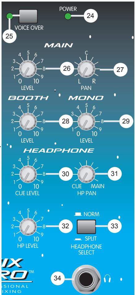
28. Booth Level
Use this control to adjust the stereo Booth Output (9) level. Adjusting this control fully clockwise will result in maximum signal level. This output is usually used for local monitoring when headphones are not convenient.
29. Mono Level
Use this control to adjust the Mono Out (4) level. Adjusting this control fully clockwise will result in maximum signal level. This output is a sum of the left and right main signals (prefader), and can be used to drive a lighting system or subwoofer crossover EQ and amp.
30. Headphone Cue Level
Use this control to set the level of the cue material present in the Headphone and Booth Outputs. With the Headphone Select switch (33) set to Normal, adjust this control to a comfortable level and the Headphone Pan (31) fully counterclockwise to listen to the cue signal in the headphones. The Headphone Cue Level control should be set in conjunction with the Headphone Pan control to achieve the desired headphone mix.
31. Headphone Pan
Use this control to pan the material in the headphone's between cue and mains while the Headphone Select switch (33) is in the Normal position. Increasing one signal level will reduce the other. While the switch is in the Split position, the Headphone Pan control will not function.
32. Headphone Level
The Headphone Level control is the master volume control for the Headphone Output (34). Adjusting this control fully clockwise will result in maximum signal level at the output.
33. Headphone Select
This switch is used to change the headphone's operational mode. When placed in the "Normal" position, stereo monitoring of the cue and/or main material is determined by the Headphone Pan (31). As you pan between the cue and main signals, you will hear both signals in the left and right headphone cups. When the Headphone Select switch is in the "Split" position, the left cup contains the cue material and the right cup contains the main material. To adjust the level in this mode, use the Cue Level control (30) to set the preferred balance and the Headphone Level control (32) to set the overall level.
34. Headphone Output
This 1/4" stereo output jack is used to power a set of stereo headphones. The tip is wired left, the ring is wired right, and the sleeve is wired to ground.
35. Stereo Output Level Indicator
This calibrated pair (L and R) of 12 segment LED meters illuminates to visually indicate program output levels. At the top of each meter is a clip LED to notify you of extreme levels and possible distortion caused by overdriving the signal.
36. X-Fader
This 45 mm stereo slider delivers crossfade capability between Channels 1 and 2. Adjusting this slider from its maximum left position to its maximum right position will pan the main output from being completely Channel 1 to completely
Channel 2. The interim from left to right produces a combination of both, allowing a smooth transition from one channel to the other. NOTE: The X-Fader is replaceable by removing the two outside mounting screws on the top of the unit. Once the screws have been removed, the slider can be pulled out and replaced with ease.

EFFECTS
The following section describes the two effects capabilities of the 3D Mix Pro. It is divided into two sub-sections for clarity and ease of explanation. Those sections are labeled EFFECTS LOOP CONTROLS and SRS SPATIAL EXPANDER.
EFFECTS LOOP CONTROLS
37. Engage
Pushing this switch in (down) activates the Effects Loop (10) so that the main signal runs through any external effects units connected to it. It is possible to listen to the effects in the cue by pressing the Loop Cue button (38). The Engage LED will illuminate to indicate the Effects Loop is active.
38. Loop Cue
Pushing this button in (down) places the effects signal from the loop on the cue bus. This allows you to listen to what your effects are doing within the headphones or booth. The Cue LED will illuminate to indicate that the Loop Cue is active.
SRS (O) SPATIAL EXPANDER
The 3D Mix Pro gets its name from the three-dimensional qualities of its built-in SRS effect. The SRS Spatial Expander creates a three-dimensional sound image from any audio source with only two conventional stereo speakers. This effect renders greater stereo separation and disperses sound more evenly throughout a room. Therefore, it produces a better stereo image around a larger area, making speaker placement and listener location less critical. You will find that it broadens your listening area and actually restores live performance ambience to your program material.
39. SRS Enable
This button activates the SRS effect when pushed in (down). The SRS enable LED will illuminate to indicate the SRS Spatial Expander is active.
40. SRS Space
The SRS Space control is used to broaden the stereo separation between the Left and Right outputs. Adjusting this control fully clockwise will result in maximum stereo imaging/separation.
41. SRS Collapse
Pressing this button will momentarily defeat the Space function of the SRS effect. It is called "Collapse" due to its effect on the stereo separation. It collapses the stereo fields from a widened spatial condition to a mono condition. The SRS Collapse switch is another great effect that can be used to create a beat or feeling in real time. By pressing and releasing this button with the beat, a swell/collapse condition occurs that is certain to become a highlight of your show.
3D MIX PRO SPECIFICATIONS
THD:
<0.05% (20 Hz - 80 KHz BW)
FREQUENCY RESPONSE:
+0 dB /-1 dB, 20 Hz - 20 kHz
HUM AND NOISE: (22 Hz - 22 kHz BW)
<-110 EIN (mic)
<-90 dBu, all controls off, any output
<-80 dBu nominal settings, gains minimum, any output
CROSSTALK:
-60 dBu (1 kHz) left to right;
-70 dBu (1 kHz) channel to channel
STEREO CHANNEL EQ (+12 dB, -22dB):
HI: 10 kHz shelving
MID: 850 Hz peaking
LOW: 70 Hz shelving
MIC CHANNEL EQ (+15 dB, -15 dB):
HI: 10 kHz shelving
LOW: 80 Hz shelving
LOW CUT FILTER: 18 dB/oct @ 75 Hz
RUMBLE FILTER:
18 dB/oct @ 40 Hz
MIN INPUT LEVELS FOR 0 dBu OUTPUT:
(All controls at maximum gain settings)
MIC: -57 dBu (1.0 mv RMS); 2 k ohms
LINE/CD: -23 dBu (55 mv RMS); 10 k ohms
PHONO (@ 1KHz): -50 dBu (2 mv RMS); 47 kohms
SRS CONTROLS:
Space, collapse switch, enable (with LED)
LOOP LEVEL:
0 dBu nominal
SIGNAL INDICATORS (LED):
Signal Present: Indicates the signal has exceeded the -20 dBu level. 12 Segment ladder indicates main output level (0 dB = 0 dBu)
PHANTOM POWER:
+15V, both mic inputs
POWER REQUIREMENTS:
15 W 115 VAC or 230 VAC (Export model)
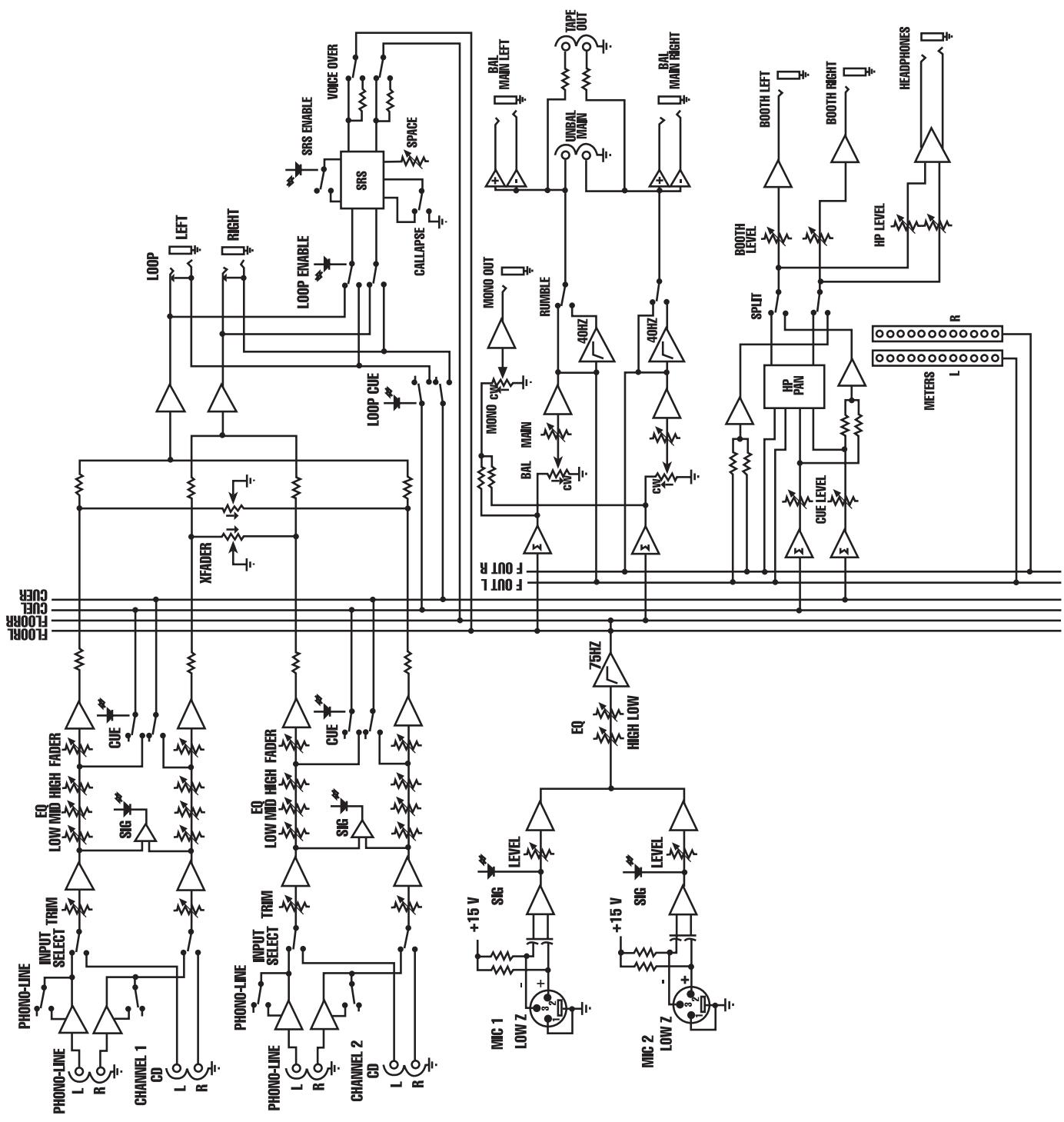
3D MIX PRO™ BLOCK DIGRAM
IMPORTANT SAFETY INSTRUCTIONS
WARNING: When using electric products, basic cautions should always be followed, including the following:
- Read these instructions.
- Keep these instructions.
- Heed all warnings.
- Follow all instructions.
- Do not use this apparatus near water. For example, near or in a bathtub, swimming pool, sink, wet basement, etc.
- Clean only with a damp cloth.
- Do not block any of the ventilation openings. Install in accordance with manufacturer's instructions. It should not be placed flat against a wall or placed in a built-in enclosure that will impede the flow of cooling air.
- Do not install near any heat sources such as radiators, heat registers, stoves or other apparatus (including amplifiers) that produce heat.
- Do not defeat the safety purpose of the polarized or grounding-type plug. A polarized plug has two blades with one wider than the other. A grounding type plug has two blades and a third grounding plug. The wide blade or third prong is provided for your safety. When the provided plug does not fit into your inlet, consult an electrician for replacement of the obsolete outlet. Never break off the grounding. Write for our free booklet "Shock Hazard and Grounding". Connect only to a power supply of the type marked on the unit adjacent to the power supply cord.
- Protect the power cord from being walked on or pinched, particularly at plugs, convenience receptacles, and the point they exit from the apparatus.
- Only use attachments/accessories provided by the manufacturer.
- Use only with a cart, stand, tripod, bracket, or table specified by the manufacturer, or sold with the apparatus. When a cart is used, use caution when moving the cart/apparatus combination to avoid injury from tip-over.
- Unplug this apparatus during lightning storms or when unused for long periods of time.
- Refer all servicing to qualified service personnel. Servicing is required when the apparatus has been damaged in any way, such as power-supply cord or plug is damaged, liquid has been spilled or objects have fallen into the apparatus, the apparatus has been exposed to rain or moisture, does not operate normally, or has been dropped.
- If this product is to be mounted in an equipment rack, rear support should be provided.
- Exposure to extremely high noise levels may cause a permanent hearing loss. Individuals vary considerably in susceptibility to noise-induced hearing loss, but nearly everyone will lose some hearing if exposed to sufficiently intense noise for a sufficient time. The U.S. Government's Occupational and Health Administration (OSHA) has specified the following permissible noise level exposures:
| Duration Per Day In Hours | Sound Level dBA, Slow Response |
| 8 | 90 |
| 6 | 92 |
| 4 | 95 |
| 3 | 97 |
| 2 | 100 |
| 1 1/2 | 102 |
| 1 | 105 |
| 1/2 | 110 |
| 1/4 or less | 115 |
According to OSHA, any exposure in excess of the above permissible limits could result in some hearing loss. Ear plugs or protectors to the ear canals or over the ears must be worn when operating this amplification system in order to prevent a permanent hearing loss, if exposure is in excess of the limits as set forth above. To ensure against potentially dangerous exposure to high sound pressure levels, it is recommended that all persons exposed to equipment capable of producing high sound pressure levels such as this amplification system be protected by hearing protectors while this unit is in operation.
SAVE THESE INSTRUCTIONS!
ESPAÑOL
<0.05% (20 Hz-80 kHz BW)
Remove these screw to
replace the X-Fader.
EFFETS
<-110 EIN (mic)
<-90 dBu, all controls off, any output
<-80 dBu nominal settings, gains minimum, any output
CROSSTALK:
-60 dBu (1 kHz) left to right;
-70 dBu (1 kHz) channel to channel
STEREO CHANNEL EQ (+12 dB, -22dB):
HI: 10 kHz shelving
MID: 850 Hz peaking
LOW: 70 Hz shelving
MIC CHANNEL EQ (+15 dB, -15 dB):
HI: 10 kHz shelving
LOW: 80 Hz shelving
LOW CUT FILTER: 18 dB/oct @ 75 Hz
RUMBLE FILTER:
18 dB/oct @ 40 Hz
MIN INPUT LEVELS FOR 0 dBu OUTPUT:
(All controls at maximum gain settings)
MIC: -57 dBu (1.0 mv RMS); 2 k ohms
LINE/CD: -23 dBu (55 mv RMS); 10 k ohms
PHONO (@ 1KHz): -50 dBu (2 mv RMS); 47 kohms
SRS CONTROLS:
Space, collapse switch, enable (with LED)
LOOP LEVEL:
0 dBu nominal
SIGNAL INDICATORS (LED):
Signal Present: Indicates the signal has exceeded the -20 dBu level. 12 Segment ladder indicates main output level (0 dB = 0 dBu)
PHANTOM POWER:
+15V, both mic inputs
POWER REQUIREMENTS:
15 W 115 VAC or 230 VAC (Export model)
NOTE IMPORTANTE CONCERNANT LA SECURITE
CONSERVEZ CES INSTRUCTIONS!
DEUTSCH
3D MIX PRO™
Rotary Level Control
HP selector switch (normal/split)
HP pan (Cue/Main)
Tape outputs (Chinch)
33. Headphone Select
34. Headphone Output
<-90 dBu, all controls off, any output
<-80 dBu nominal settings, gains minimum, any output
CROSSTALK:
-60 dBu (1 kHz) left to right;
-70 dBu (1 kHz) channel to channel
STEREO CHANNEL EQ (+12 dB, -22dB):
HI: 10 kHz shelving
MID: 850 Hz peaking
LOW: 70 Hz shelving
MIC CHANNEL EQ (+15 dB, -15 dB):
HI: 10 kHz shelving
LOW: 80 Hz shelving
LOW CUT FILTER: 18 dB/oct @ 75 Hz
RUMBLE FILTER:
18 dB/oct @ 40 Hz
MIN INPUT LEVELS FOR 0 dBu OUTPUT:
(All controls at maximum gain settings)
MIC: -57 dBu (1.0 mv RMS); 2 k ohms
LINE/CD: -23 dBu (55 mv RMS); 10 k ohms
PHONO (@ 1KHz): -50 dBu (2 mv RMS); 47 kohms
SRS CONTROLS:
Space, collapse switch, enable (with LED)
LOOP LEVEL:
0 dBu nominal
SIGNAL INDICATORS (LED):
Signal Present: Indicates the signal has exceeded the -20 dBu level. 12 Segment ladder indicates main output level (0 dB = 0 dBu)
PHANTOM POWER:
+15V, both mic inputs
POWER REQUIREMENTS:
15 W 115 VAC or 230 VAC (Export model)
Effective Date: July 1, 1998
What This Warranty Covers
Your Peavey Warranty covers defects in material and workmanship in Peavey products purchased and serviced in the U.S.A. and Canada.
What This Warranty Does Not Cover
The Warranty does not cover: (1) damage caused by accident, misuse, abuse, improper installation or operation, rental, product modification or neglect; (2) damage occurring during shipment; (3) damage caused by repair or service performed by persons not authorized by Peavey; (4) products on which the serial number has been altered, defaced or removed; (5) products not purchased from an Authorized Peavey Dealer.
Who This Warranty Protects
This Warranty protects only the original retail purchaser of the product.
How Long This Warranty Lasts
The Warranty begins on the date of purchase by the original retail purchaser. The duration of the Warranty is as follows:
| Product Category | Duration |
| Guitars/Basses, Amplifiers, Pre-Amplifiers, Mixers, Electronic Crossovers and Equalizers | 2 years * (+ 3 years) |
| Drums | 2 years * (+ 1 year) |
| Enclosures | 3 years * (+ 2 years) |
| Digital Effect Devices and Keyboard and MIDI Controllers | 1 year * (+ 1 year) |
| Microphones | 2 years |
| Speaker Components (incl. speakers, baskets, drivers, diaphragm replacement kits and passive crossovers) and all Accessories | 1 year |
| Tubes and Meters | 90 days |
[denotes additional warranty period applicable if optional Warranty Registration Card is completed and returned to Peavey by original retail purchaser within 90 days of purchase.]
What Peavey Will Do
We will repair or replace (at Peavey's discretion) products covered by warranty at no charge for labor or materials. If the product or component must be shipped to Peavey for warranty service, the consumer must pay initial shipping charges. If the repairs are covered by warranty, Peavey will pay the return shipping charges.
How To Get Warranty Service
(1) Take the defective item and your sales receipt or other proof of date of purchase to your Authorized Peavey Dealer or Authorized Peavey Service Center.
OR
(2) Ship the defective item, prepaid, to Peavey Electronics Corporation, International Service Center, 412 Highway 11 & 80 East, Meridian, MS 39301 or Peavey Canada Ltd., 95 Shields Court, Markham, Ontario, Canada L3R 9T5. Include a detailed description of the problem, together with a copy of your sales receipt or other proof of date of purchase as evidence of warranty coverage. Also provide a complete return address.
Limitation of Implied Warranties
ANY IMPLIED WARRANTY, INCLUDING WARRANTYES OF MERCHANTABILITY AND FITNESS FOR A PARTICULAR PURPOSE, ARE LIMITED IN DURATION TO THE LENGTH OF THIS WARRANTY.
Some states do not allow limitations on how long an implied warranty lasts, so the above limitation may not apply to you.
Exclusions of Damages
PEAVEY'S LIABILITY FOR ANY DEFECTIVE PRODUCT IS LIMITED TO THE REPAIR OR REPLACEMENT OF THE PRODUCT, AT PEAVEY'S OPTION. IF WE ELECT TO REPLACE THE PRODUCT, THE REPLACEMENT MAY BE A RECONDITIONED UNIT. PEAVEY SHALL NOT BE LIABLE FOR DAMAGES BASED ON INCONVENIENCE, LOSS OF USE, LOST PROFITS, LOST SAVINGS, DAMAGE TO ANY OTHER EQUIPMENT OR OTHER ITEMS AT THE SITE OF USE, OR ANY OTHER DAMAGES WHETHER INCIDENTAL, CONSEQUENTIAL OR OTHERWISE, EVEN IF PEAVEY HAS BEEN ADVISED OF THE POSSIBILITY OF SUCH DAMAGES
Some states do not allow the exclusion or limitation of incidental or consequential damages, so the above limitation or exclusion may not apply to you.
This Warranty gives you specific legal rights, and you may also have other rights which vary from state to state.
If you have any questions about this warranty or service received or if you need assistance in locating an Authorized Service Center, please contact the Peavey International Service Center at (601) 483-5365 / Peavey Canada Ltd. at (905) 475-2578.
Features and specifications subject to change without notice.

PEAVY
Features and specifications subject to change without notice.
Peavey Electronics Corporation • 711 A Street • Meridian • MS • 39301
(601) 483-5376 • FAX (601) 486-1678 • www.peavey.com