
B&W CWM CINEMA 6 - Home theater speaker B&W - Free user manual and instructions
Find the device manual for free B&W CWM CINEMA 6 B&W in PDF.

| Product Type | In-wall speaker for home cinema |
| Brand | B&W |
| Model | CWM CINEMA 6 |
| Usage | Center, left, right, surround or stereo speaker |
| Installation type | Flush-mounted in hollow wall, solid wall or with PMK pre-mount kit |
| Package contents | Wall chassis with speakers and crossover, front grille with cloth, paint protection mask, mounting template |
| Color | Semi-matte white (paintable) |
| Recommended enclosure volume | Greater than 20 liters (0.8 ft³) |
| Minimum distance from corners | 0.5 meter (20 inches) |
| Minimum distance from sensitive devices | 50 cm (20 inches) from magnetic fields |
| Recommended cable resistance | Less than 0.5 ohm (ideal 0.2 ohm) |
| Fixing | 6 screws for mounting brackets |
| Customization | Paintable with provided mask |
| Warranty | 5 years (2 years for electronic components) |
| Break-in | Approximately 15 hours of normal use |
Frequently Asked Questions - B&W CWM CINEMA 6 B&W
User questions about B&W CWM CINEMA 6 B&W
0 question about this device. Answer the ones you know or ask your own.
Ask a new question about this device
Download the instructions for your Home theater speaker in PDF format for free! Find your manual B&W CWM CINEMA 6 - B&W and take your electronic device back in hand. On this page are published all the documents necessary for the use of your device. B&W CWM CINEMA 6 by B&W.
USER MANUAL B&W CWM CINEMA 6 B&W
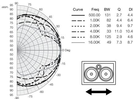
Polar Response Horizontal
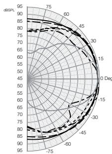
Polar Response Vertical
Curve Freq BW Q DI 500.00 149 2.4 3.8 1.00K 131 2.7 4.4 2.00K 104 3.5 5.4 4.00K 44 8.3 9.2 8.00K 102 3.5 5.5 16.00K 51 7.1 8.5
Contents
English
Owner's Manual. 2
Limited Warranty............4
Français
Ooyniec Xpnoewc...26
περιρομενη
evyyunon. 29
Pysckn
PykoBoIDCTBO NO
3Kcnpnyatau.. 30
OrpaHnueHna
rapaHTnra. 33
Česky
Návod k použití……34
Záruka 37
Polski
Instrukcja
uzytkownika 38
Gwarancja 40
日本語
取掇説明書 41
保证期間 43
中文
用户手册 44
有限保修 46
EU Declarations of
Conformity. 50
Technical
Specifications.....51-52
English Owner's manual
Dear customer,
Thank you for choosing B&W. Please read this manual fully before unpacking and installing the product. It will help you to optimise its performance. B&W maintains a network of dedicated distributors in over 60 countries who will be able to help you should you have any problems your dealer cannot resolve.
Environmental Information

All B&W products are designed to comply with international directives on the Restriction of Hazardous Substances
(RoHS) in electrical and electronic equipment and the disposal of Waste Electrical and Electronic Equipment (WEEE). These symbols indicate compliance and that the products must be appropriately recycled or processed in accordance with these directives. Consult your local waste disposal authority for guidance.
Carton Contents
Check in the carton for:
Wall frame/baffle with driver units and crossover unit
Grille with backing scrim fabric
Paint Mask
Mounting template
Introduction
The CWM Cinema 6 is primarily intended for home theatre application as a centre channel speaker but it may equally well be used as front left and right or surrounds or for 2-channel audio.
No matter how good the speakers themselves, they will not deliver their full potential unless properly installed. Please read through this manual fully. It will help you optimise their performance.
The CWM Cinema 6 speaker may be installed during construction of the studwork wall or at a later date. If possible, installation during construction of the wall is preferred however the CWM Cinema 6 pre-mount kit will be required.
Speaker Positioning
Check that there is no conflict with other installations (pipe work, air conditioning, power cabling etc.). In existing drywall construction, use a stud-finding tool to map the construction accurately and a pipe detector to scan the proposed installation position.
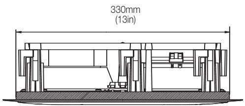
Refer to the section drawing of the speaker and ensure that there is enough clearance behind the plasterboard (sheetrock) for the clamps to swing out fully.
Avoid installing the speakers in the same cavity as flimsy ducting, which may be induced to rattle.
The speakers are designed to operate satisfactorily in a wide range of cavity volumes, ideally above 20 litres (0.8 cu ft), so make sure the volume is not too restricted by cross studs.
In solid wall construction, be prepared to provide a cavity in the wall that extends outside the boundaries of the speaker's frame, otherwise bass performance will be compromised.
The speakers are balanced for half-space mounting (ie flush in a wall, ceiling or soffit). Placement near a wall/ceiling junction or in a corner may give rise to too much bass and a boomy quality to the sound. Try to keep the speakers at least 0.5m (20in) from wall/ceiling edges.
The following sections give guidance on optimum positioning, but this may be modified in line with domestic constraints.
Home Theatre Centre Channel Applications
The ideal position for a centre channel speaker is behind the centre of the screen, however this can only be realised when using an acoustically transparent projection screen. In most cases the centre speaker will be positioned in a laterally central position either directly above or directly below the screen. Choose the position that is nearest ear height. Figure 1 illustrates these positioning guidelines.
Home Theatre Front Channel Applications and 2-channel audio
For multi-channel home theatre the left and right speakers should be approximately 0.5m (20 in) to the left and right of the screen and as near the centre height of the screen as possible. Figure 2 illustrates these positioning guidelines.
Best imaging for stereo is obtained when the speakers are mounted in the wall approximately at ear height and making an angle between 40irc and 60irc at the centre of the listening position.
Home Theatre Surround Channel Applications
The speakers should be positioned 60cm (2 ft) or more above head height.
5.1 Channel: The horizontal angle to the centre of the listening position should be approximately 120irc round from the centre of the screen. Figure 3.1 illustrates this arrangement.
6.1 Channel: Position two speakers to the sides in line with the centre of the listening area and one centrally behind the listeners Figure 3.2 illustrates this arrangement.
7.1 Channel: Position two speakers to the sides in line with the centre of the listening area and two behind the listeners, subtending an angle of approximately 40irc . Figure 3.3 illustrates this arrangement.
Stray Magnetic Fields
The speaker drive units create stray magnetic fields that extend beyond the boundaries of the cabinet. We recommend you keep magnetically sensitive articles (CRT television and computer screens, computer discs, audio and video tapes, swipe cards and the like) at least 0.5m (20 in) from the speaker. LCD and plasma screens are not affected by magnetic fields.
Preparing For Installation Choosing cable
Excessive resistance in the speaker cable wastes power and alters the frequency response of the speaker. Always try to keep the resistance as low as possible with the loop resistance preferably below 0.5 ohms for non-critical applications and below 0.2 ohms for best results. Use the table of figure 7 to calculate the minimum gauge of cable required.
Fitting The Wall Frame/Baffle (existing wall construction/retrofit)
Figure 4 illustrates this procedure.
Position the template at the desired location of the speaker. The template is marked with both vertical and horizontal centre lines to aid alignment.
Trace round the outer edge of the template and cut neatly just inside the line.
To improve the mechanical integrity of the wall and reduce the likelihood of rattles, we recommend you apply a bead of mastic/culking along the joints between the back of the plasterboard (sheetrock) and the studs in the vicinity of the speaker.
Run the cable to the aperture, allowing enough length to comfortably connect the speaker, but not too much, as the excess may rattle against the structure.
Fitting the Wall Frame/Baffle (new drywall construction)
Figure 5 illustrates this procedure.
The speaker can be installed once the wall is completed in the same manner as retrofitting, but it is easier to position and cut the hole if the optional premount kit (PMK) is used before the plasterboard is fitted.
Staple or nail the PMK to the studs as described in the instructions with the kit. Run the cable and secure it to the fixing point on the PMK. Allow enough length to comfortably connect the speaker, but not too much, as the excess may rattle against the structure.
Results are affected by how well the plasterboard (sheetrock) is attached to the studs and we recommend you apply a bead of mastic/culking as well as screwing or nailing the panels to the studs in the vicinity of the speaker.
Once the board is fitted, the inner flange of the PMK serves as a guide for a hole router or saw.
If extra acoustic isolation to adjoining rooms is required or some protection against the spread of fire, use the optional back box in place of the PMK. Follow the instructions with the back box for fitting and running the cable.
When fitting the plasterboard (sheetrock), use mastic/caulking between the sheets and the back box to avoid rattles. Rout or saw out the speaker aperture using the back-box flange as a guide. Depending on the diameter of the router, you may need to square off the corners with a saw.
Fitting the Wall Frame/Baffle (solid wall construction)
In order for the bass performance not to be compromised, the speaker requires a cavity volume of at least 20 litres (0.8 cu ft). This means that, in a standard 10cm (4 in) thick wall, the cavity will extend beyond the boundaries of the speaker frame. It is possible to provide this cavity simply by using a lintel, covering the hole with plasterboard (sheetrock) and fitting the speaker as described above for retrofitting into a drywall. (Figure 6) However, the back box provides a useful means of defining a minimum volume.
Follow the instructions with the back box for fitting and running the cable. If using a wet plaster finishing method, first apply a thin layer of PVA adhesive (polyvinyl-based caulking) onto the back box before plastering to avoid rattles as a result of the plaster shrinking away from the back box as it dries.
If using plasterboard (sheetrock), stick the sheets to the surfaces of the back box using flexible mastic/-caulking. Rout out the aperture using the flange as a guide. Depending on the diameter of the router, you may need to square off the corners with a saw.
In all cases, we recommend not using cement or mortar to fix the back box into the brick or block-work. Rattles are best avoided by using flexible mastic/caulking and wedges.
Damping the Wall Cavity
Fill the wall cavity or back box, but not the space immediately behind the speaker, with unlined fiberglass or mineral wool matting. The packing density should be just enough to comfortably prevent the material from dropping or sagging over time. In an open wall cavity, fill to a distance of at least 30cm (1 ft) above and below the speaker.
IMPORTANT: Ensure that the materials you use meet local fire and safety regulations.
Connecting and Fitting the Speaker (all installation types)
All connections should be made with the equipment switched off.
Connect the cable, observing the correct polarity.
With the grille removed, position the speaker in the aperture and screw in the 6 screws visible from the front. These screws automatically swing out clamping dogs that locate behind the mounting surface. Ensure that they have located properly before fully tightening the screws. A certain amount of flexing of the frame is allowed to take up unevenness in the mounting surface, but do not over-tighten the screws as excessive distortion of the speaker frame may result.
Customising
The frame has a paintable white semi-matte finish, ready if necessary to be re-finished to match room decor. Fit the paint mask before re-finishing. Do not re-finish the drive units or baffle area behind the grille. Avoid touching the drive units, as damage may result.
Before painting the grille, peel off the fabric scrim from the back, otherwise the pores will get clogged and the sound will be impaired. If the scrim does not stay in place properly when replaced, spray the back of the grille mesh (NOT the scrim) with a light coating of 3M SprayMount adhesive or similar.
Fine Tuning
If the sound is too bright, increasing the amount of soft furnishing in the room (heavier curtains for example) may help balance the sound. Conversely, reducing the amount of soft furnishing may help brighten a dull sound.
Some rooms suffer from "flutter echoes" - echoes that "bounce" between parallel room boundaries. Flutter echoes can colour the sound of the speakers in the room. Test for flutter echoes by standing in the middle of the room and clapping your hands. Flutter echoes can be reduced by placing irregular shaped items or non-reflective surfaces - bookshelves, rugs or pictures for example - on one of the offending walls or floor.
Running-in Period
The performance of the speaker will change subtly during the initial listening period. If the speaker has been stored in a cold environment, the damping compounds and suspension materials of the drive units will take some time to recover their correct mechanical properties. The drive unit suspensions will also loosen up during the first hours of use. The time taken for the speaker to achieve its intended performance will vary depending on previous storage conditions and how it is used. As a guide, allow up to a week for the temperature effects to stabilise and 15 hours of average use for the mechanical parts to attain their intended design characteristics.
However, longer run-in periods (as long as a month) have been reported and there is evidence to suggest that this has little to do with the speaker changing and more to do with the listener getting used to the new sound. This is especially so with highly revealing speakers such as these where there may be a significant increase in the amount of detail compared with what the listener has previously been used to; the sound may at first appear too "up front" and perhaps a little hard. After an extended period of time the sound will seem to mellow, but without losing clarity and detail.
Limited Warranty
This product has been designed and manufactured to the highest quality standards. However, if something does go wrong with this product, B&W Group Ltd. and its national distributors warrant free of charge labour (exclusion may apply) and replacement parts in any country served by an official B&W distributor.
This limited warranty is valid for a period of five years from the date of purchase or two years for electronics including amplified loudspeakers.
Terms and Conditions
1 The warranty is limited to the repair of the equipment. Neither transportation, nor any other costs, nor any risk for removal, transportation and installation of products is covered by this warranty.
2 This warranty is only valid for the original owner. It is not transferable.
3 This warranty will not be applicable in cases other than defects in materials and/or workmanship at the time of purchase and will not be applicable:
a. for damages caused by incorrect installation, connection or packing,
b. for damages caused by any use other than correct use described in the user manual, negligence, modifications, or use of parts that are not made or authorised by B&W,
c. for damages caused by faulty or unsuitable ancillary equipment,
d. for damages caused by accidents, lightning, water, fire heat, war, public disturbances or any other cause beyond the reasonable control of B&W and its appointed distributors,
e. for products whose serial number has been altered, deleted, removed or made illegible,
f. if repairs or modifications have been executed by an unauthorised person.
4 This guarantee complements any national/regional law obligations of dealers or national distributors and does not affect your statutory rights as a customer.
How to claim repairs under warranty
Should service be required, please follow the following procedure:
1 If the equipment is being used in the country of purchase, you should contact the B&W authorised dealer from whom the equipment was purchased.
2 If the equipment is being used outside the country of purchase, you should contact the B&W national distributor in the country of residence who will advise where the equipment can be serviced. You can call B&W in the UK or visit our web site to get the contact details of your local distributor.
To validate your warranty, you will need to produce the warranty booklet completed and stamped by your dealer on the date of purchase. Alternatively, you will need the original sales invoice or other proof of ownership and date of purchase.
François
IopcoeHHeHne uYctaHOBka AC Ha MeCTO (dJIa BCEx TnIOB HcTaNJIaCm)
Bce 3neKtpnueckne coeHHeHnI dOJIHHbI npOn3BOIDTcBc npu BbIKIOUeHHOM oObOpYOBaHm.
IpoCoeHnHte Ka6eB,co6nIoJa npaBnHyo nonpnoctb.
Помет范围内 AC (6e3 peWEtKN) B OTBepCTne n 3aBHTNte 6 BUNIMbIX CnpeDIn BNHTA. Пп NTOM NOBOPOTHble 3aKIMbl ABTOmatUYeCKn PpNKpePJIHOt pamy K pINTe.Y6eINTEcB, YTO BCE ONH 3aHJI IN npABINbHOE NIOXeHHe, 3aTEM NIOHOCtB 3aTAHNTe BNHTbl. Pama 06bnaaet ONpeJeHHoN IROKocTbO, KOMNEHCUPyOuSeH He POBHOCTb MOHTaXHNO NIOBEPXHOCTn.ODhako He cNe dyET 3aTARNBaTH BNOBcTb CNIWKOM CNILbHO, TAK KaK LIIWHEE NCKPbVBeHne pAmbl MOKET 3aTpYdHbYCTaHOBY DEKOPaTHBOH peWEtKN.
Оденьka no Mectу
Pama KONOHN OKpaSeHa 6eNoI NOnyMaTOB0Kpacko, roTOBOK KnepeKpacke DnA COOTBeTCTBnHInTebpery KOmHaTb.IIpeXJe, cem KpacNTb,NaHehTe NaACMacky dNnOkoPacKn. HeDonyckaTne NaOpdAnHHKpackn Ha DNHAMNKu nnHa NoBepxHOctb NepeJHneN 3a 3aunTHoPeWetKo. N36eaiTe KaCAnHHn DnΦcY3OpOBDNHAMKOB, T.K. Bbl MoKeTe IN NOBpeDuTb.
Ipepe Okpakoekopatmbno peeTeKn ydaJIte TkaHb cee obaPthOcTcPOHObl, HnAue npocBeTb B TkaHN 3akynoparTcN NOCTpaAdet KaHeCTBO 3ByKa. Ecnn npu Bo3BpTa He MeCTo kAnb He BeSyed leXaTb PNOCKo, PaCbnlnte Ha obaPTHy cTcPOHy peeTeKn (a HE HaTKaHb) HemHoro a3pO3OnbHoro KlenJzero BeuecTb, HanpImep, 3M SprayMount.
ToHkaHaCTpoKa
Ecnn 3Byk cnNtKOM pe3kn, no6abBe T MrgKoM me6eJIb N KOMHATE (HanPIMep, NOBecBe T RAxJbe WToPbl), nnHaobopot - y6epnte nx, ecnn 3Byk rnyoxn n 6e3X43HeHHb.
HeKoTOpbIe NOMEUHINCTpaIaIOT O3ΦΦeKTA 3xO, BbI3BaHHoro napJIeNBJHOCTbIO CTEN. IIOIoBHOe 3X0 MOKeT OKpAcNTb 3ByK AC B KOMHATE. IpOBepbTe CBOICTBa NOMEUHIN, YdApINB B JAnOuN IN PnICJyUnBaCb K b6IcTbIM OT3ByKAM. IN MOKHO yMeHbUaBt 3a CHT ICNoJIb3OBAHIN HEPeYJrPbIX NOBepXHOCTe, TAKNX KAK KNK NII KpyTHorAbaPTHa Me6eNb Ha OJHOI N3 CTEN INI KOBeR Ha NOLY.
PpOpeB n npupa60Ka
3ByaHHe AC cIeKa MeHReTcB TceHHe NaaybHOro
peHOna IpcnLnuBaHn. EcNI KOLOHka xpaHnIacb XOIOHOM NOMEueHH,TO dJIa DEmNpHyoUxh MATEpHAnOB N IOBeBa DNAMHKOB NOTpe6yTec HKeKToTOpe BPEMa H BOCTaHOBLeHne MEXAHueCCKX CBOITb. POIBeC dNcF cy30pa TAKCe cERKa CHNJaet CBOIO JeeCTKOCTB T CEHeHne nepBbIX YacOB pa6Otbl. BPEMa KOTOpoe Notpe6yTec AC dJIa NOHOro BbIXOda Ha paCteHbIe XapakTePunctKN 3abNCIT OT yCNOBna XpaHENr INHTeHCNBocTH nCOnJb3OBAHn. Ka npabINO, Notpe6yTec HeJeIHa yCTpaHENr TEMpePAtpHBx 3ΦΦeKTOB n OKJIO 15 cacOB Ha DOCTNXeHE MEXAHueCCKMn YactAmn JeNaembIX XapakTePunctNK.
KHAMHOrdaNoCTyNaIOT3bIBbI,HTOHeo6XoIMM
00eeJeIINTeBbIepeIOpnpabOtKN(HaNPmep, Mecu),ODnako3TO,KAKnPabIno,HEImeet
OTHOWeHHN KIN3MeHEnHM B CBOYCTBAX AC,ACKopee
BCero CBra3aHO C pINbBkaHcM CUYsTaEeK HOBOMY
JrNEHoro 3ByuHaHIO.3To npExDe BCero OTHOCNTK
KONOHkAM C BvICOKo pa3peWauUeien CNOco6HOCTbHO,
rDE CUYsATeLIO MOKeT OKpblTcBA 3NaHTeBHO
60JIbuee KOINueCTBO DeTalee,YEM TO,K KOTOPOM OH
pAAeH eINbIK;3BYuaHHe NOHauany MoKeT NOKa3aTbCRA
YepecyP «BbINyeHHbIM」 HEMHO TpyDHBm DnI
BOcIPnTnA。ODnako nocJe Boone nn Mehee
IpdoJnxTeBHLORo BVPemHn BAM NOKaKeTcR,HTO 3ByK
CTaN MRue Ne PnIRaThee,HO6e3 KaOK-Hn6ybJyTePi
YCHOCTN IN DETaJIbHOCTN.
OrpaHnueHHa rapaHTna
DaHHeo n3dJIeN 6bIIO pa3pa60TaHO n npO3BeDeHO B COOTBECTBm C bVlCOaHJIMM cTaNapTAMn KaeeCTBa. OAnkao, npi o6hApjEHN KAKoJ-Ni6o HEnCpABHOCTN, KOMPAnHnB W&W Group Ltd. n eH aCuHOnAHbHbIe DnCTPNb6bIOTOpb I rapAHTnpyHOT BeCNPlaTHbI pEMOH (CyuEcTBYOT HEKOTOpbIe NCKJIOUeHn) n 3aMeHy CuTeH B NIO6oi CTpaHe, O6cLyXuBaEMO OOpNuaHbIbIM dNCTPNb6IOTOpM KOMPAnHn B&W
JaHnA OrpaHnueHnA rapaHTn DaeCTBnTebHa Ha nepNoI OndHOro Ioga Co nI pyNObpeTeHn N3dJIINKoHeHbIM NOTpBeNTJEM.
YcnoBra rapaHTn
1 DaHHa rapaHTnOrpaHmNBAeTcNoHHKoI o6OpYOBaHn.3aTpTaI no nepeBO3Ke nIObIe pyrHe 3aPaTbI, a TaKke pnc npi OTKnIOUeHn, nepeBO3Ke nHCTaJInpuROBaHn n3dEIn He nOKpbBaIoTc DaHHoRpaHTne.
2 DeTbNe DaHnOH paAHTN pacnPoCTpaHReTcT ToIbKo Ha nePbHOaHaNbHoro BlaJeBHe. paAHTN He MoKet 6blb NepeDaHa DpyrOmy NlUy.
3Даннаг rapaHTnpaCnpocTpaHReTcTToNbKOHa Te HeCNpBaHOCTN,KOTOpBle BbI3BaHbI,DepeKTHbIMM MaTePnAanm n/Inn DepeKTAmn npi pOn3BODCTBe HA MMeON TpNoOBpeTeHnI He pacnpoCTpaHReTcT:
a. Na NOBpeKdEHNRA, Bb3BaHHbIe HeNpBaUNbHOH INCTaJIJIaUnei, NIOcOeINHeHnEM IIN yNAKOKBOKOI,
6. Na NOBpeJdeHn, Bb3BaHHBe IcNoJIb3OBAHHeM, He COOTBeTCTByUcIM OINcAHHOMy B pyKOBoJDCTBE No npImeHeHnO, a TaKxHeNpPaBnIbHbIM ObpaUeHnEM, MoINcIuPObaHnE M INcIOJIb3OBAHnEM 3aNaChbIX qAcTeH, He pOn3BEdEHbIX INI He ODo6peHNbIX KOMnAnHei B&W,
B. NaOBpeXDeHIN, BbI3BaHbHBe HEnCpBaBbIM IJIHEnOxDoxaUzIM BCNOMoRATeMbHbIMObopydOBaHHeM,
r. Ha NOBpeXdHnI, Bbl3BaHHbIe HeCcaCThblIM CNyuaMn, MONHnei, BOIO, NOKAPOM, BOHOI, Ny6blHbIMN 6ecnpaKamm IINJxJe IIObIMN dpyrIMN qakTopAmn, He noJaadaUoImn nOd KOHTpOlb KOMpanHn B&W n e odpnnaIbHbx DnCTpr6bIoTOPOB,
Д. Издени, срейнный Homep KOTopbix 6bln
Изmedен, унчToxKeH Илсделан
Hey3Habaemblm,
e. Na IN3dJIIN, NOUHNI JIJI MOJINKauJIa KOTOpbIX IPON3BODINHCb JIcOM, He yONHNOHMOUEHNbIM KOMNAHnei B&W.
4 DaHHa rapaHTna RbIraTc DOnonHeHnEM K NaIOHOHaJIbIM/perIOHOHaJIbIM 3aKOHOdaTeNbCTBAM,KOTOpBM IOdYNHIAOTCA DInIePb INI NaIOHOHaJIbHbIe NIDCTPNbIoTOptbl,TO
ecTb npn BO3HKnHOBeHn npOTNbOpeHn, HauNoHaIbHbIe/peHNoHaIbHbIe 3aKoHoJaTeNbCTBa NMeIOT npNOpNTHyU Cnly. DAnHra rapaHTn He hapyaet BaWnx npab notpe6nten.
Kya o6paTntb83ra rapaHTnHbIM 06cIyXNBaHHeM
Pn Heo6xOaMocTn noluyehnra pataHnHoro 0cbnykBaHn, BbInONHteneCneDyIOueIe Iar:
1 Ecnn obopydobaHne nCnOJIb3yeTcB CCTpaHe npOn6peTeHHa, Bam HeoXoIMNo CB3aTbCa c yOnIHOmOeHHbIM dInepom KOMpanHn B&W, y KOtTopo 6blno npOn6peTeHO obopydobaHne.
2 Ecnn obOpdyobAHne nCnObl3yETc 3a npedenamn cTpaHb npno6peTeHHa, Bam Heo6xOJIMNo C8Ba3aBcN c HauNOHaJIbHbIM dIcTpN6bIOTOPOM KOMNaHIN B&W dAnHOH cTpaHe, KOtOpBn NocOBeTyET Bam, Ie moKHO noHNHTb obOpdyobAHne. Bb MOXeTe No3BOHNT b KOMNaHIn B&W B BenNKo6pntAHm nn JKe nocEtNb hAa Be6caiT, YTO6bI y3HaTb KOthAKThb aAdpec BaWero MeCTHORO dNcTpN6bIOTopa.
Длноуени rapaHTnHoro 6cnykuaHnA, Bam Heo6xoIMO npEOCTABNTb rapaTnHbI tALOH, 3aONJIHeHHb BaMmДINepom n c NoCTabJIeHNO mB DeH npIO6peTeHN OOBpyOBOAH neaTbIO; IInnJKeK npOdaXn INn DpyRoDoka3aTeNbCTBO BlaJeHN OOBpyOBOAHnEM n DaTb npIO6peTeHN.
EU DECLARATION OF CONFORMITY
We,
B&W Group Ltd.
whose registered office is situated at
Dale Road, Worthing, West Sussex, BN11 2BH, United Kingdom
declare under our sole responsibility that the products:
CWM Cinema 6
comply with the EU Electro-Magnetic Compatibility (EMC) Directive 89/336/EEC, in pursuance of which the following standards have been applied:
EN 61000-6-1 : 2001
EN61000-6-3:2001
EN 55020:2002
EN 55013:2001
and comply with the EU General Product Safety 2001/95/EC, in pursuance of which the following standard has been applied:
EN 60065:2002
This declaration attests that the manufacturing process quality control and product documentation accord with the need to assure continued compliance.
The attention of the user is drawn to any special measures regarding the use of this equipment that may be detailed in the owner's manual.
Signed:

G Edwards
Executive Vice President, Operations
B&W Group Ltd.
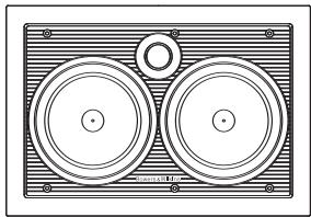
CWM Cinema 6
Technical features Nautilus™ tube-loaded tweeter
Woven glassfibre bass/midrange driver
Description 2-way in-wall speaker system
Drive units 1x 25mm (1 in) tube-loaded softdome high-frequency 2x 160mm (6 in) woven glassfibre cone bass/midrange
Frequency response 60Hz - 22kHz ±3dB on reference axis
Frequency range -6dB at 50Hz and 30kHz
Sensitivity 92dB spl (2.83V, 1m)
Nominal impedance 8Ω (minimum 5.0Ω)
Crossover frequency 3.5kHz
Maximum recommended 150W continuous into 8Ω on unclipped programme amplifier power
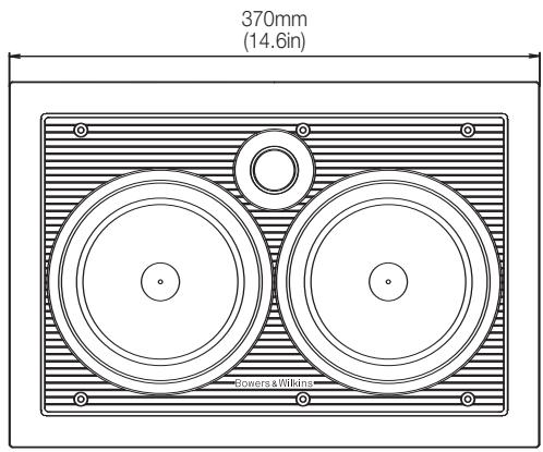
Frame size Height: 255mm (10.1 in)
Width: 369mm (14.6 in)
Cut-out size Height: 217mm (8.5 in)
Width: 332mm (13.1 in)
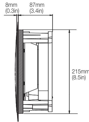
Min. depth required 90mm (3.6 in) behind ceiling surface
8mm (0.3 in) in front of ceiling surface
Net weight 2.9kg (6.4 lb)
Bowers & Wilkins
B&W Group Ltd
Dale Road
Worthing West Sussex
BN11 2BH England
T +44 (0) 1903 221 800
F +44 (0) 1903 221 801
info@bwgroup.com
www.bowers-wilkins.com
B&W Group (UK Sales)
T +44 1903 221 500
Euksales@bwgroup.com
B&W Group North America
T +1 978 664 2870
E marketing@bwgroupusa.com
B&W Group Asia Ltd
T +852 2 869 9916
E info@bwgroup.hk
Nautilus is a trademark of B&W Group Ltd.
Copyright © B&W Group Ltd. E&OE
Printed in China.


- Contents
- English
- Français
- Pysckn
- Česky
- Polski
- 日本語
- 中文
- English Owner's manual
- Environmental Information
- Carton Contents
- Introduction
- Speaker Positioning
- Home Theatre Centre Channel Applications
- Home Theatre Front Channel Applications and 2-channel audio
- Home Theatre Surround Channel Applications
- Stray Magnetic Fields
- Preparing For Installation Choosing cable
- Fitting The Wall Frame/Baffle (existing wall construction/retrofit)
- Fitting the Wall Frame/Baffle (new drywall construction)
- Fitting the Wall Frame/Baffle (solid wall construction)
- Damping the Wall Cavity
- Connecting and Fitting the Speaker (all installation types)
- Customising
- Fine Tuning
- Running-in Period
- Limited Warranty
- Terms and Conditions
- How to claim repairs under warranty
- François
- IopcoeHHeHne uYctaHOBka AC Ha MeCTO (dJIa BCEx TnIOB HcTaNJIaCm)
- Оденьka no Mectу
- ToHkaHaCTpoKa
- PpOpeB n npupa60Ka
- OrpaHnueHHa rapaHTna
- YcnoBra rapaHTn
- Kya o6paTntb83ra rapaHTnHbIM 06cIyXNBaHHeM
- EU DECLARATION OF CONFORMITY
- CWM Cinema 6
- Bowers & Wilkins
Brand : B&W
Model : B&W CWM CINEMA 6
Category : Home theater speaker