Atlas Medium - Washing machine CECOTEC - Free user manual and instructions
Find the device manual for free Atlas Medium CECOTEC in PDF.


User questions about Atlas Medium CECOTEC
0 question about this device. Answer the ones you know or ask your own.
Ask a new question about this device
Download the instructions for your Washing machine in PDF format for free! Find your manual Atlas Medium - CECOTEC and take your electronic device back in hand. On this page are published all the documents necessary for the use of your device. Atlas Medium by CECOTEC.
USER MANUAL Atlas Medium CECOTEC
CECOTEC TR ATLAS MEDIUM
CECOTEC TR ATLAS LARGE
EU01_100626_CECOTEC TR Atlas Medium
EU01_106795_CECOTEC TR Atlas Large
EN • The coding in this manual is generic and applies to all code variants of the appliance.
- Aluminium alloy frame
- Spoked rim
- Tyres
- Disc brakes
- Removable battery 48V 15.6 Ah
- Motor
- Shimano 11-speed gear system
- Front suspension fork
- Handlebar stem
- Telescopic saddle post
- Rear shock absorber
NOTE:
The graphics in this manual are schematic representations and may not exactly match the product.
2. BEFORE USE
- This electric bike features packaging designed to protect it during transport. Remove the electric bicycle from its box and remove all packing material. You can keep the original box and other packaging elements in a safe place. This will help you prevent damage to the appliance when transporting it in the future. If you wish to dispose of the original packaging, make sure all items are recycled properly.
- Check that all parts and components are included and in good condition. If there is any piece missing or not in good condition, contact the official Cecotec Technical Support Service immediately.
Box content
- E-Bike
- Charger
- Tools
- Instruction manual
- Do not remove the product's serial number in order to keep proper traceability if technical assistance is required.
3. ASSEMBLY
Step 1
Place the product in an upright position. You can identify the vertical position of the box by checking the "this side up" sign on the side of the box with directional arrows. Open the box carefully with the help of a box cutter or scissors.
Step 2
The e-bike is packaged to prevent scratches and damage. Once the box has been opened, carefully remove the parts. To do this, hold the electric bike by the stem and top tube and lift it vertically. Place it carefully on the floor, away from the packaging and in an upright position
Step 3
Apart from the main body of the electric bike, the box contains smaller boxes containing other components such as the charger, pedals and tool kit. Remove them with care.
Step 4
The front wheel comes packaged with the electric bike, and is attached to the frame with the help of a zip tie. The packaging protects the hydraulic brake and tyres from damage. To remove the front wheel from the frame, carefully cut off the zip tie. Next, be sure to remove the protective packaging from the wheel before you start installing it on the electric bike.
Step 5
Look for any zip ties that may still be left on the wheel. Cut them carefully without damaging the electric bicycle.
Step 6
Keep the electric bike in an upright position and remove all packaging. Then you can start assembling the product.
Assembling the handlebar. Fig. 2
- Remove the handle on the right side of the handlebar by loosening its screw.
- Insert the gear shifting knob at the handlebar end first, then the brake lever. Once installed, they should be positioned opposite to the brake lever and lever on the left side of the handlebars already mounted at the factory.
- Loosen the four screws on the stem caps with the 4 mm Allen wrench and remove the caps.
- Carefully place the handlebars in the now open stem cover. Ensure all cables are untangled and positioned in front of the front fork so as not to obstruct movement once the front wheel is mounted.
- Align the handlebar slots on the stem. Then, replace the caps and tighten the screws clockwise. First make sure that the screws fit into the threads by turning them gently by hand, and then tighten them firmly with the wrench.
Front wheel mounting. Fig. 3
- Place the electric bicycle frame upside down on a stable surface. This ensures that no parts of the electric bike are damaged during assembly. Remove any packaging or zip ties that may remain on the front wheel.
- Stand in front of the fork and remove the wheel axle installed in the fork by loosening counterclockwise. Next, carefully insert the wheel by matching the brake disc between the pads of the brake caliper.
Note: If the brake disc does not fit, you must loosen the inside of the front brake caliper by separating the pads. - Once the brake disc has been inserted, fit the wheel hub into the front fork end housing and then insert the axle from the side opposite the brake disc.
- Once the shaft is inserted, hand tighten it clockwise keeping the quick release handle in the open position. When you feel some resistance, operate the locking handle in the closed position.
NOTE: It is important that the tightening of the shaft is neither excessively high nor excessively loose. The closing handle should harden progressively when closing, reaching its maximum hardness point towards the end of its travel. If when closing the crank handle you notice an excessive hardness at mid-travel, unscrew the shaft slightly and close the closing handle again until you find the optimum hardness.
Assembling the pedals. Fig. 4
- Check the marking indicating the left pedal and the right pedal.
- To mount the pedals, screw the right pedal clockwise and the left pedal counterclockwise.
Assembling the light, reflectors, and bell
- Install the front light and rear reflector by attaching the rubber or plastic clamp to the light itself, clamping them around the handlebars and seat post respectively.
NOTE: This bicycle is equipped with a telescopic seatpost, place the reflector as high as possible until it is just below the saddle to avoid interfering with the moving mechanism of the seatpost.
- Install the bell on the handlebar so that it is within thumb reach on the desired side.
- Install the orange colored side reflectors on the wheel spokes using the reflector fitting slots.
Saddle adjustment
- Make sure that the seat post is fully extended by means of the actuating knob located on the left side of the handlebar.
- For the saddle height pre-adjustment, the saddle should be at the same height as your hip. Please note that the correct position should be one in which your hip is not tilted to one
side when the pedal is in its bottom position and your foot is fully engaged in the pedal. Once the pre-adjustment has been made, finally adjust the saddle height using the locking lever. Note that when the saddle is raised, the knee should be neither fully stretched nor very bent when the pedal is at the bottom.
- Adjust the saddle properly to ensure maximum efficiency and comfort during exercise. The saddle is in the correct position if the user has a slightly bent knee when one of the pedals is at a 90 degree angle relative to the ground.
- To indicate the maximum height that the saddle can be adjusted, you will see vertical line markings following the word MIN.
Assembling the battery. Fig. 5.
- The electric bike comes with a removable battery. Remove it from the box carefully. Place it in the space provided for it in the lower central tube of the bike. Slide it in its lower part until it snaps in and then push the upper part until you hear the locking mechanism.
- Once in place, insert the spanner into the hole on the left side of the bike. Turn the key clockwise to fix the battery in its place.
Charging the battery
Only use the original charger supplied. To start charging, insert the charger into the socket at the bottom of the battery or into the charging socket on the side of the bike, and plug it into a power source. The battery will fully charge in 4-6 hours.
4. OPERATION
The electric bicycle will start assisting with electric power once you start pedalling.
DISPLAY
Display interface and operation
Fig. 6
- Power button
- +/- adjustment button
Handlebar control operation
Fig. 7
- Upper adjustment knob ∧
- Confirmation and multifunction button "M"
- Lower adjustment knob v
How to use buttons
| Type of press | Description |
| Short press | Press the button and release it quickly. Upon release, the function will activate. |
| Long press | Press and hold the button. When the timeout exceeds the set time (usually 2 seconds), the function will activate. |
| Combined short press | It consists of briefly pressing a button and, while holding it down, pressing another button. Release both buttons after the second button has been pressed for the set time (usually within 1 second) to activate the function. |
| Combined long press | It involves pressing and holding two buttons simultaneously. When the buttons are held down for longer than the configured long press duration (usually 1 second), the corresponding function will be activated. |
Switching on/off the display
- To turn the display on or off, press and hold the power button.
- When the display is turned on, a logo is showed for 3 seconds.
- After the communication connection is established, the display will always show the main interface.
Information displays
Main interface
Activated by default when switching on the display, it shows standard information such as time, riding speed, partial kilometres travelled, battery charge level and electric assistance level. All information is updated in real time.
Figure 8 shows the basic function interface of the electric bicycle display.
Fig. 8
- Front light on (only models with integrated light)
- Clock
- Real-time speed
- Trip distance
- Battery information
- Assistance level
Interface I
Primarily displays speed information, including trip mileage, average speed, maximum speed and total mileage, with the trip mileage (TRIP) being the same as on the main interface.
Fig. 9
- Trip mileage
- Average speed
- Max. speed
- Total mileage
The speed display is a 3-digit number with one decimal place, with a maximum value of 99.9 KM/H.
The trip mileage is usually a 4-digit number including one decimal place; once it exceeds 999.9 KM, the decimal point is no longer displayed, showing a direct 4-digit number with a maximum value of 9999 KM. When the maximum value is exceeded, the number displayed is the actual mileage value modulo 10000.
The total mileage is a 6-digit number with one decimal place. When it exceeds 99,999.9 KM, it will no longer display the decimal point and will display a 6-digit number, with a maximum value of 999,999 KM. When the maximum value is exceeded, the number displayed is the actual mileage value modulo 10000.
Interface II
- It mainly displays battery-related information, including battery voltage, percentage of capacity, total charge cycles and remaining range.
Figure 10
- Battery voltage
- Total charge cycles
- Remaining range
-
Capacity percentage
-
Total charge cycles are provided by the Battery Management System (BMS). If the BMS does not provide this information, it will display ----.
- The remaining range information is calculated by the controller based on the BMS capacity of the battery. If the controller does not provide the remaining range information, it will display ----.
Interface III
- It mainly shows the usage time statistics for different modes of assistance during the trip. Fig. 11
- Statistical data are calculated by the display according to the actual driving status and displayed as a percentage.
- The time-of-use statistics for the assistance modes can be reset to zero by a data clearing operation.
Interface IV
It mainly displays power statistics, including average engine power and maximum power.
Fig. 12
- Average motor power
- Maximum motor power
Interface V
It mainly displays the statistics of the rider's power and the motor power ratio, which requires controller support.
Fig. 13
- Cyclist power
- Motor power ratio
Error code interface
This interface automatically turns on when the display receives an error from the controller, it shows a detailed error code indicating problems in the electrical system. This code appears numerically in the section where the speed is displayed. Fig. 14

Note: If the system does not support BMS communication, the display cannot obtain accurate RANGE information, and the RANGE value will be shown as “----”.
Assistance level adjustment
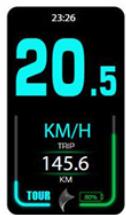
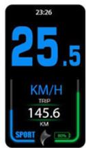
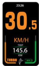
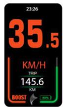
Briefly press the +/- adjustment button on the display, or the v/^ buttons on the handlebar control to change the assist level mode and the amount of assist delivered shown in the bar on the left.
Using the +/- level button on the display the levels are cycled upwards. After reaching the BOOST level (maximum level), by continuing to press the button, it will return to the OFF level, completing the cycle.
Using the buttons on the handlebar control you can increase or decrease the level without completing the cycle.
You can switch between the following levels of assistance:
OFF > ECO > TOUR > SPORT > TURBO > BOOST


Light control function (Only models with integrated light)
Press and hold the ^ button on the handlebar control to turn on the integrated light. The display will show the light on icon in the upper left corner, indicating that the light is on, and the brightness of the display will decrease.
Press and hold the button again to turn off the light.
Battery and power assistance indicator
If the battery drops below 5% or the voltage is too low, the display will show a warning and the battery outline will flash slowly. In this case, the system must be turned off and on again. The warning will disappear when the voltage is sufficient and the load is above 5%.
The following table shows the battery percentage and the corresponding icons:
| Charge percentage | Battery indicator light | Description |
| 100% to 11% |  | Battery capacity is displayed as a percentage. The bar will decrease as the battery is consumed. |
| 10% or less | 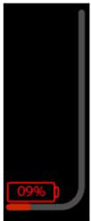 | Low charge: Red icon. |
| 5% or less | 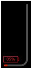 | Critical charge: Red icon and battery symbol flashes. |
Trip data deletion
Data deletion is used to clear information such as subtotal mileage (TRIP), average speed and maximum speed recorded on interface I.
- After turning on the display, go to the I-interface and simultaneously press and hold the power button of the display and the "M" button of the handlebar control.
- Use the v/\^ buttons to select an option in the pop-up dialog box, then confirm by pressing the "M" button.
- If you do not perform any operation within 30 seconds, or if you press and hold the +/- button, you will exit the data erase mode.
- After deleting the data, the trip meter (TRIP), average speed and maximum speed will be reset to zero. The accumulated mileage (ODO) cannot be cleared from the display and requires specialized maintenance tools to reset.
Settings menu
The display offers parameter setting functions and display adjustments.
Within 10 seconds after the display turns on, simultaneously press and hold the power button on the display and the "M" button on the handlebar control to access the setup menu.
Using the v/∧ buttons you will navigate through the menu settings. To enter the selected setting press the "M" button on the handlebar control. Made the desired settings with the v/∧ buttons and press the "M" button again to confirm and return to the menu.
Pressing the EXIT option will exit the configuration menu to the Main Interface.
In this menu you can make changes to the units of measurement, time, display illumination, auto-off time, set unlock pin, maintenance warnings, consult battery and controller information, and reset all parameters.
NOTE: The "Advanced settings" setting can only be used by Cecotec technical staff with a password.
| Setting | Interface | Parameter | Parameter value | Comments |
| Unit setting | 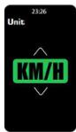 | Unit | Km/hMPH | Default value:Km/h |
| Clock setting | 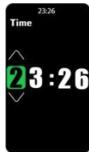 | Time | The factory setting writes the current time. | It can be modified. |
| Lighting configuration |  | Lighting | Level 1, 60% lightingLevel 2, 80% lightingLevel 3, 100% lighting | Default value: 3 |
| Automatic shut-off time |  | Automatic shut-off | Value: OFF,5-30 min | Default value:5 min.“OFF” Indicates no automatic shutdown. |
| Password setting at start-up | 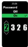 | Password | Value: OFF and ON; When the parameter value is set to “ON”, the user can set a 4-digit password. | Default setting: OFF. |
| Maintenance reminder settings |  | Maintenance | Fixed value | Default value: 5000 km |
| Restore factory settings |  | Reset button | Restore factory settings. | All parameters will be restored to the factory settings. |
Error information
The display can alert you to problems with your bicycle. If a fault is detected, a flashing error code will be displayed. Even if the code is displayed, the buttons will continue to function normally. If no button is pressed within 5 seconds, the display will show the error code again.
Here is what the error code interface looks like:
Error codes
| Error code | Meaning | Suggested operation |
| 04 | The throttle does not return to zero (remains high). | Check if the throttle has returned |
| 05 | Throttle failure | Check the throttle |
| 07 | Overvoltage protection | Check battery voltage |
| 08 | Motor Hall signal cable failure | Check the motor |
| 09 | Motor phase cable failure | Check the motor |
| 11 | Motor temperature sensor failure | Check the controller |
| 12 | Current sensor failure | Check the controller |
| 13 | Battery temperature failure | Check the battery |
| 14 | Controller temperature too high, protection point reached | Check the motor |
| 21 | Speed sensor failure | Check the installation position of the speed sensor. |
| 22 | BMS communication failure | Replace the battery |
| 30 | Communication failure | Check the connector to the controller |
Recommendations for gear changes
To improve the range of the electric bike, we recommend changing gear ratios according to the speed. A lower gear is best for low-speed off-roading and travelling. At higher speeds it is best to choose a higher gear. Releasing the pressure on the pedals during shifting will allow smooth assistance and better autonomy.
5. WI-FI CONNECTIVITY AND MOBILE APP
Scan the following QR code to download the app, access the manual, guides, and technical support.

Download the Ananda Ride app from Google Play or App Store.
- Then go to the Ananda Ride application, and register your account with an email address and password. You will need to confirm your e-mail address.
- Activate the Bluetooth on your mobile device. Turn on your bike's display by pressing and holding the power button for a few seconds. Automatically the Bluetooth connection indicator will flash blue, indicating that the display has entered pairing mode. Note: Remember to be close to the bike to ensure connectivity, and make sure your bike's bluetooth is active and blinking.
- Go back to the Ananda Ride App, and click on "Add eBike", to start the pairing. You will notice that the device has been detected. After successful pairing, the bluetooth indicator will remain blue, and you will be able to enjoy the available functions. Note: If a connection is not made within 30 seconds, the indicator will flash red three times before turning off, indicating that the pairing attempt has failed.
Please note that it is not possible to include a complete application guide in this manual, as it is a free third-party application and is updated continuously. For more information, please refer to the instructions available within the application itself or on Google Play Store or App Store.
6. CLEANING AND MAINTENANCE
- It is recommended to use a damp cotton cloth or sponge instead of a hose or water jet.
- It is recommended to clean the electric bike after each use. However, you can wash it weekly. This will help to extend the lifespan of the electric bike.
- Use soaps and care products for bicycles that do not attack plastics and seals, which can be found in specialised shops. You can also use a soap solution or liquid detergent. Do not use aggressive products or strong degreasing agents.
- You can dry clean the electric bike with a cotton cloth or microfibre cloth to prevent corrosion.
- The battery bracket is designed to allow water to drain off more quickly and the battery contacts to dry easily. For this to happen, the bracket area and the plug must be kept clean. The battery contacts are provided with a coating that protects the surface against corrosion and wear.
Maintenance
Keep tyre pressure at least 2.5 bar. Maintain tyre pressure to avoid punctures. If you notice any irregularities, take the electric bicycle to a mechanic.
Bike chain maintenance
- Lubricate the chain regularly to avoid annoying chain noises and other problems when changing gears. Lubricate the chain every 100-200 km or when the chain is dry or dirty. Use a specific lubricant for bicycle chains, preferably one with a wax or Teflon base. Apply the lubricant to the inside of the chain while turning the pedals backwards. Remember to clean the chain before applying the lubricant for best results.
- When greasing the chain, make sure that the brake discs are not soiled and that the sprocket is not engaged. Spray where the chain slides smoothly and wipe off excess lubricant with a cloth. Only use specific chain lubricant.
- The proper bicycle chain tension is the tension at which you can move the chain slightly vertically between approximately 1 cm and 3 cm without it being too slack or too tight.
We recommend that you have your vehicle serviced and maintained once every 6 months by a repair shop.
Maintenance control
| MONTHLY | ||
| Regular cleaning | Frame | Use a low pressure water jet or a damp cloth to clean it and then wipe it dry. Do not get the electrical components wet when cleaning the electric bike. |
| Transmission | Use a bicycle transmission degreaser on the chain, flywheel and gears to clean them thoroughly. It is essential to remove dirt and dust that accumulate in the transmission. Always clean the transmission before lubricating the chain. | |
| Bike chain | Use a low pressure water jet or a damp cloth to clean it and then wipe it dry. Do not get the electrical components wet when cleaning the electric bike. | |
| Wheels | Check for loose spokes. | |
| Wheels | Check the tyre pressure every week and maintain it within the limits specified on the tyre. | |
| Bolts | If there is play in the bolts and screws, tighten them immediately. | |
| EVERY 6 MONTHS (AT AUTHORISED REPAIR SHOP) | ||
| Deep cleaning | Brakes | Clean the brakes and brake pads to prevent squealing. If they are worn, replace them with new ones. Replace brake cables every 6 months for proper operation. |
| Wheels | Check the wheels for worn tread. Replace wheels if necessary. | |
| Bike chain | Check the chain wear with the chain wear indicator. | |
| Handlebar grips | Replace the grips if they are worn. | |
| Gear shifting | Replace the gear shift cables every 6 months for best performance. | |
| Front hub | Clean and regrease the bearing inside the hub. | |
| EVERY YEAR (AT AUTHORISED REPAIR SHOP) | ||
| Full revision | Every component | Completely disassemble the electric bicycle. Clean and re-grease all threaded components after assembly. Inspect frame, suspension and all components, repair or replace parts as necessary.Degrease the transmission and replace the chain. |
7. DISPOSAL OF OLD ELECTRICAL AND ELECTRONIC APPLIANCES


This symbol indicates that, according to the applicable regulations, the product and/or batteries must be disposed of separately from household waste. When this product reaches the end of its service life, you must remove the batteries/accumulators and take it to a collection point designated by local authorities.
For detailed information on the most appropriate way to dispose of electrical and electronic equipment and/or batteries, consumers should contact their local authorities.
Compliance with the above guidelines will help to protect the environment.
Information regarding national packaging recycling systems and their marking can be found on our website.
8. INFORMATION ON DATA STORED BY CONNECTED PRODUCTS IN ACCORDANCE WITH REGULATION (EU) 2023/2854 (“DATA REGULATION”)
Cecotec's connected products and related services are those that generate different data and information during use. In accordance with the provisions of the Data Regulation, through this document Cecotec provides you with information about your rights concerning the data generated and about how to access such data.
This right allows you to use the data for any lawful purpose, including, among others, product and/or service optimisation or contracting post-sale services with third parties.
As a user, you may exercise your right of access, within the limits provided for by the Data Regulation, through the email address data.act@cecotec.es. To protect the generated data—and in order to prevent fraud or identity theft—CECOTEC may require additional information to verify your status as a user.
Data is stored for a determined period of time.
9. COPYRIGHT
The intellectual property rights over the texts in this manual belong to CECOTEC INNOVACIONES, S.L. All rights reserved. The contents of this publication may not, in whole or in part, be reproduced, stored in a retrieval system, transmitted, or distributed by any means (electronic, mechanical, photocopying, recording or similar) without the prior authorization of CECOTEC INNOVACIONES, S.L.
1. PIÈCES ET COMPOSANTS
Image 1
5. CONNETTIVITÀ WI-FI E APP
Download de Ananda Ride-app via Google Play of de App Store.
Fig./Img./Abb./Afb./Rys.1
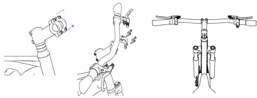
Fig./Img./Abb./Afb./Rys. 2
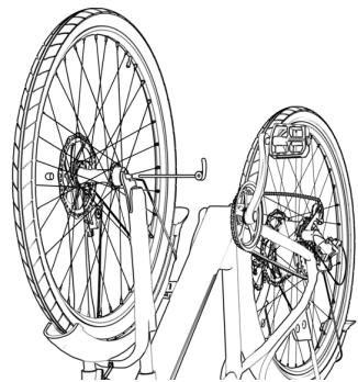
Fig./Img./Abb./Afb./ Rys. 3

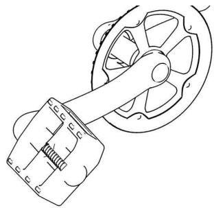
Fig./Img./Abb./Afb./Rys. 4
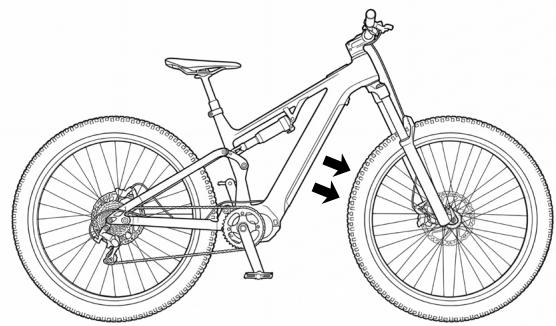
Fig./Img./Abb./Afb./Rys. 5

Fig./Img./Abb./Afb./ Rys. 6
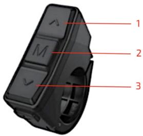
Fig./Img./Abb./Afb./Rys. 7
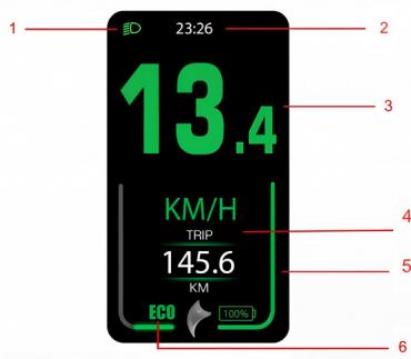
Fig./Img./Abb./Afb./ Rys. 8
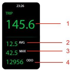
Fig./Img./Abb./Afb./ Rys. 9

Fig./Img./Abb./Afb./Rys.10

Fig./Img./Abb./Afb./ Rys. 11

Fig./Img./Abb./Afb./ Rys. 12

Fig./Img./Abb./Afb./ Rys. 13
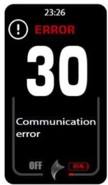
Fig./Img./Abb./Afb./ Rys. 14
www.cecotec.es
- NOTE
- BEFORE USE
- BOX CONTENT
- ASSEMBLY
- STEP 1
- STEP 2
- STEP 3
- STEP 4
- STEP 5
- STEP 6
- ASSEMBLING THE HANDLEBAR. FIG. 2
- FRONT WHEEL MOUNTING. FIG. 3
- ASSEMBLING THE PEDALS. FIG. 4
- ASSEMBLING THE LIGHT, REFLECTORS, AND BELL
- SADDLE ADJUSTMENT
- ASSEMBLING THE BATTERY. FIG. 5
- CHARGING THE BATTERY
- OPERATION
- DISPLAY INTERFACE AND OPERATION
- HANDLEBAR CONTROL OPERATION
- SWITCHING ON/OFF THE DISPLAY
- INFORMATION DISPLAYS
- MAIN INTERFACE
- INTERFACE I
- FIG. 9
- INTERFACE II
- FIGURE 10
- INTERFACE III
- INTERFACE IV
- FIG. 12
- INTERFACE V
- FIG. 13
- ERROR CODE INTERFACE
- ASSISTANCE LEVEL ADJUSTMENT
- LIGHT CONTROL FUNCTION (ONLY MODELS WITH INTEGRATED LIGHT)
- BATTERY AND POWER ASSISTANCE INDICATOR
- TRIP DATA DELETION
- SETTINGS MENU
- ERROR INFORMATION
- RECOMMENDATIONS FOR GEAR CHANGES
- WI-FI CONNECTIVITY AND MOBILE APP
- CLEANING AND MAINTENANCE
- MAINTENANCE
- BIKE CHAIN MAINTENANCE
- DISPOSAL OF OLD ELECTRICAL AND ELECTRONIC APPLIANCES
- INFORMATION ON DATA STORED BY CONNECTED PRODUCTS IN ACCORDANCE WITH REGULATION (EU) 2023/2854 (“DATA REGULATION”)
- COPYRIGHT
- PIÈCES ET COMPOSANTS
- CONNETTIVITÀ WI-FI E APP
Brand : CECOTEC
Model : Atlas Medium
Category : Washing machine