
APC20 - MIDI Controller AKAI - Free user manual and instructions
Find the device manual for free APC20 AKAI in PDF.
| Product Type | MIDI Controller |
| Brand | AKAI |
| Model | APC20 |
| Dimensions (approx.) | 25 x 19.5 x 4 cm |
| Weight (approx.) | 1.5 kg |
| Power Supply | 12 V DC, 2 A (AC adapter included) |
| Connectivity | USB 2.0 (MIDI), DC input |
| Required Software | Ableton Live (professional version for APC provided on CD) |
| Clip Launch Grid | 8 x 5 buttons with LEDs (colors: off, amber, green, red) |
| Potentiometers | 8 (volume, pan, sends SEND1-3, USER1-3) |
| Transport Buttons | Play, Stop, Rec |
| Navigation Buttons | Bank Select (up/down, left/right), Shift |
| Additional Functions | Note Mode, Session Overview, Clip Stop, Solo/Cue, Record Arm, Activators |
| Compatibility | Windows (7 and later), macOS (10.6 and later) |
| Included Accessories | 12V 2A AC adapter, USB cable, installation CD |
| Care and Cleaning | Clean with a soft, dry cloth. Do not use abrasive products. |
| Safety | Do not expose to moisture or liquids. Unplug before cleaning. |
| Spare Parts and Repairability | Contact AKAI after-sales service for any repairs. |
| General Information | Dedicated controller for Ableton Live, can be used as a standard MIDI controller. |
Frequently Asked Questions - APC20 AKAI
User questions about APC20 AKAI
0 question about this device. Answer the ones you know or ask your own.
Ask a new question about this device
Download the instructions for your MIDI Controller in PDF format for free! Find your manual APC20 - AKAI and take your electronic device back in hand. On this page are published all the documents necessary for the use of your device. APC20 by AKAI.
USER MANUAL APC20 AKAI
This Quickstart Guide is intended to give you a brief overview of the functionality and features of the Akai APC20 Ableton Controller.
APC20 is designed for performance with Ableton Live. In this manual, you will find instructions on how to connect the APC20 and use its basic features with Ableton Live – Akai Professional APC Edition. APC20 can also be used in "generic mode" as a controller with other virtual DJ applications that use MIDI protocol.
If you already own Ableton Live, make sure to download the latest Ableton Live update for full APC20 support at www.ableton.com/latest Versions. We recommend referring to the Ableton manual on the CD as well as the lessons available in the software itself.
SOFTWARE INSTALLATION
To install the Akai Profesional APC Edition of Ableton Live, simply insert the included CD into your computer, then follow the on-screen instructions.
To access the software after installing it, you can find it here:
PC: Start Menu All Programs Ableton Live [Version Number]
Mac: Applications Ableton Live [Version Number].
In order for Ableton Live to properly recognize the APC20, however, you must connect the controller before opening the software, and you must set your Preferences accordingly. See the CONNECTION DIAGRAM and SOFTWARE SETUP sections for instructions on how to do this.
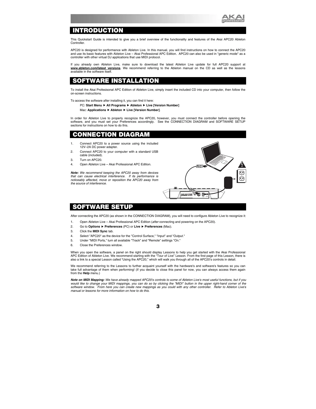
CONNECTION DIAGRAM
- Connect APC20 to a power source using the included 12V-2A DC power adapter.
- Connect APC20 to your computer with a standard USB cable (included).
- Turn on APC20.
- Open Ableton Live - Akai Professional APC Edition.
Note: We recommend keeping the APC20 away from devices that can cause electrical interference. If its performance is noticeably affected, move or reposition the APC20 away from the source of interference.
SOFTWARE SETUP
After connecting the APC20 (as shown in the CONNECTION DIAGRAM), you will need to configure Ableton Live to recognize it:
- Open Ableton Live - Akai Professional APC Edition (after connecting and powering on the APC20).
- Go to Options Preferences (PC) or Live Preferences (Mac).
- Click the MIDI Sync tab.
- Select "APC20" as the device for the "Control Surface," "Input" and "Output."
- Under "MIDI Ports," turn all available "Track" and "Remote" settings "On."
- Close the Preferences window.
When you open the software, a panel on the right should display Lessons to help you get started with the Akai Professional APC Edition of Ableton Live. We recommend starting with the "Tour of Live" Lesson. From the first page of this Lesson, there is also a link to a special Lesson called "Using the APC20," which will walk you through all of the APC20's controls in detail.
We recommend referring to the Lessons to further acquaint yourself with the hardware's and software's features so you can take full advantage of them when performing! (If you decide to close this panel for now, you can always access them again from the Help menu.)
Note on MIDI Mapping: We have already mapped APC20's controls to some of Ableton Live's most useful functions, but if you would like to change your MIDI mappings, you can do so by clicking the "MIDI" button in the upper right-hand corner of the software window. From here you can create new mappings as you could with any other controller. Refer to Ableton Live's manual or lessons for more information on how to do this.
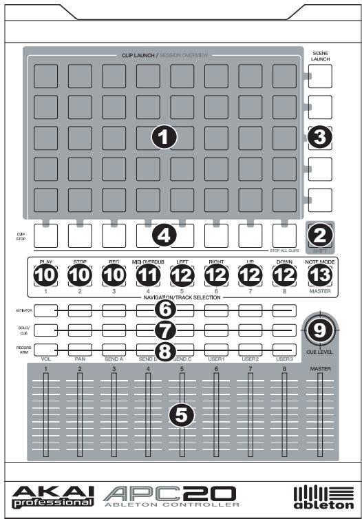
TOP PANEL OVERVIEW
1. CLIP LAUNCH / SESSION OVERVIEW
- While in Clip Launch View (the default), this 8x5 grid of buttons is used to launch clips in Ableton Live. The 8 vertical columns represent 8 tracks in the software while the 5 horizontal rows represent 5 clip slots in each track. In this view, the button LED colors represent the following:
OFF - empty
AMBER - clip present, not playing
GREEN - clip present, playing
RED - clip present, recording
When the SHIFT button is held, this grid will change to Session Overview. In this view, each button represents an entire 8x5 grid of clip slots in the software (that is, each button represents a different Clip Launch View). Selecting one will change the Clip Launch View. This allows you to access and use more than the 5 rows and 8 tracks represented by just one Clip Launch View. While in Session Overview, the button LED colors represent the following:
OFF - no clips are present in this 8x5 grid
AMBER - clips are present in this 8x5 grid, which is currently selected
GREEN - clips are present in this 8x5 grid, which contains clip slots that are currently playing
RED - clip are present in this 8x5 grid, but no clip slots are currently playing
Examples: If you have 16 tracks with 20 clips in each track, the "first" Clip Launch View will represent Clips 1-5 of Tracks 1-8.
If you hold SHIFT and press the second button in the first row, after releasing SHIFT the Clip Launch View will represent Clips 1-5 of Tracks 9-16.
If you hold SHIFT and press the first button in the second row, after releasing SHIFT the Clip Launch View will represent Clips 6-10 of Tracks 1-8.
Note: In the software, a red rectangle around an 8x5 grid of clips represents APC20's current Clip Launch View. You can change/shift the Clip Launch View with APC20's controls (e.g. in the Session Overview).
Note: If the current Clip Launch View is "between" two 8x5 grids in the software, both buttons representing those two grids will light.
- SHIFT - Holding this button down lets you access extra controller features (printed in amber on the control surface), such as Session Overview or a track available in the NAVIGATION / TRACK SELECTION section. You can change the mode of the TRACK CONTROL FADERS by holding shift and pressing one of the RECORD ARM / FADER MODE buttons.
- SCENE LAUNCH - These buttons triggers an entire row of clips, called a "scene." All clips in that scene will be triggered, including those not represented in that Clip Launch View.
-
CLIP STOP - These buttons stop all clips playing in the corresponding track, including those not represented in that Clip Launch View. Hold the SHIFT button and press any CLIP STOP button to stop all clips playing when they reach the end. (This differs from the STOP button, which stops playback immediately.)
-
TRACK CONTROL FADERS - These faders control the VOL, PAN, SEND1-3 and USER1-3 levels of the current 8 tracks and Master. Select what the faders control by holding SHIFT and pressing the corresponding RECORD ARM / FADER MODE button above them.
- TRACK ACTIVATORS - When lit, the current corresponding track is active. Pressing a button will mute it (the button will become unlit). Press it again to activate it.
- SOLO / CUE - Solos the selected track, sending it to the Cue Output. Press it again to un-solo it.
- RECORD ARM / FADER MODE - Arms the selected track for recording. Press it again to disarm it. Hold down SHIFT and press one of these buttons to select what the TRACK CONTROL FADERS control (e.g., VOL, PAN, SEND1, etc.).
- CUE LEVEL - Controls the volume sent to the Cue Output and the volume of sample auditioning.
NAVIGATION / TRACK SELECTION
These control specific functions in Ableton Live. When SHIFT is held down, pressing one of these buttons will select a track - 1-8 or MASTER.
- TRANSPORT CONTROLS - These transport controls - PLAY, STOP, and REC - represent the same functions in the software.
- MIDI OVERDUB - Turns MIDI Overdub on or off.
- BANK SELECT - These pads move the cursor/selection in Ableton Live by one track (left or right) or by one scene (up or down). Holding SHIFT while pressing this pad will move the selection by 8 tracks (left or right) or by 5 scenes (up or down), effectively changing the Clip Launch View (see #1).
- NOTE MODE - Press this button to put the CLIP LAUNCH / SESSION OVERVIEW buttons into Note Mode. In Note Mode, the 8x5 grid will be divided into two equal halves with each button representing a note in Ableton Live's Drum Rack. Moving left-to-right and bottom-to-top within the left half of the grid, the buttons ascend chromatically (C1, C#1, D1, D#1, etc.) from C1 to G2. The right half of the grid ascends similarly from G#2 to D#3. (This is ideal for using with Drum Rack, but it can also be used to play melodic lines with any MIDI device.)
Note: In the software, a red rectangle around an 8x5 grid of clips represents APC20's current Clip Launch View. You can change/shift the Clip Launch View with APC20's controls (e.g. SHIFT + BANK SELECT).
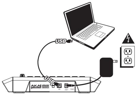
REAR PANEL OVERVIEW
- POWER ON / OFF - Turns the APC20 on or off.
- DC POWER ADAPTER INPUT - Plug in the included 12V-2A DC power adapter here.
- USB CONNECTION - Plug a standard


2A +

POWER
USB cable into this outlet and into the USB port of your computer. This connection is used to send and receive MIDI data to and from your computer.
4. POWER ADAPTER RESTRAINT - You can secure a power adapter cord to this restraint to prevent accidental unplugging.
INTRODUCCION
Brand : AKAI
Model : APC20
Category : MIDI Controller