USER MANUAL MPD32 AKAI
EDIT MODE PARAMETERS 11
EDITING THE PADS 12
NOTE PARAMETERS. 13
PROGRAM CHANGE PARAMETERS 14
EDITING KNOBS. FADERS AND EXPRESSION PEDAL 15
CONTROL CHANGE PARAMETERS 16
AFTERTOUCH PARAMETERS 17
INIncrement/DECREMENT PARAMETERS (knobs only) 18
EDITING BUTTONS 19
CONTROL CHANGE PARAMETERS 19
PROGRAM CHANGE PARAMETERS 20
EDITING NOTE REPEAT 21
NOTE REPEAT BUTTON MODE 22
NOTE REPEAT PARAMETERS - GATE, SWING 22
EDITING TIME DIVISION 23
DEFAULT TIME DIVISION 23
BUTTON MODE 23
EDITING TRANSPORT CONTROL 24
EDITING TAP TEMPO 24
EDITING FOOTSWITCH INPUTS 25
CONTROL CHANGE PARAMETERS 25
DRUM PAD PARAMETERS 26
OTHER FUNCTIONS 26
GLOBAL MODE 27
KILL MIDI - Page1 27
MIDI COMMON CHANNEL - Page 2. 27
LCD CONTRAST - Page 3 28
PAD SENSITIVITY - Page 4. 28
PAD VELOCITY CURVE - Page 5. 28
PAD THRESHOLD - Page 6. 29
MIDI CLOCK - Page 7 29
TAP TEMPO AVERAGE - Page 8 29
SAVE SETUP - Page 9 30
SYSEX TX - Page 10 30
VERSION-Page 11 30
PROGRAM CHANGE MODE 31
PROG CHANGE (Program Change) 31
PROG+BANK (Program Change with Bank Change) 31
RESETTING FACTORY DEFAULTS 32
FREQUENTLY ASKED QUESTIONS 33
TROUBLESHOOTING 34
TECHNICAL SPECIFICATIONS 35
CONTACT INFORMATION 35
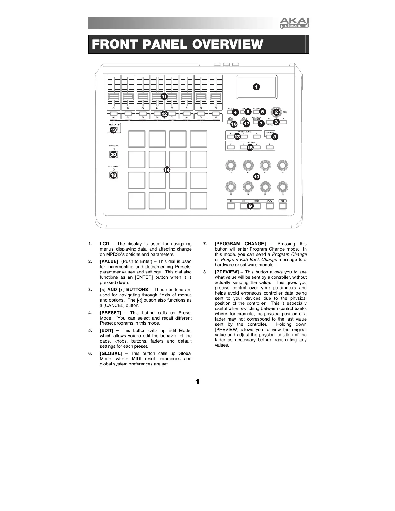
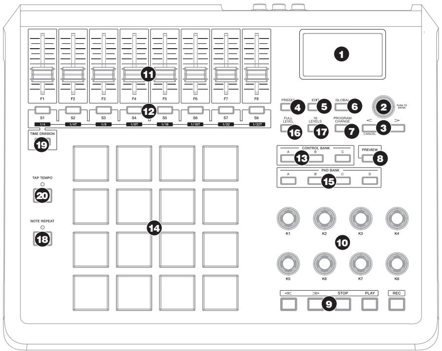
FRONT PANEL OVERVIEW
- LCD - The display is used for navigating menus, displaying data, and affecting change on MPD32's options and parameters.
- [VALUE] (Push to Enter) - This dial is used for incrementing and decrementing Presets, parameter values and settings. This dial also functions as an [ENTER] button when it is pressed down.
- [<] AND [>] BUTTONS - These buttons are used for navigating through fields of menus and options. The [<] button also functions as a [CANCEL] button.
- [PRESET] - This button calls up Preset Mode. You can select and recall different Preset programs in this mode.
- [EDIT] - This button calls up Edit Mode, which allows you to edit the behavior of the pads, knobs, buttons, faders and default settings for each preset.
-
[GLOBAL] - This button calls up Global Mode, where MIDl reset commands and global system preferences are set.
-
[PROGRAM CHANGE] - Pressing this button will enter Program Change mode. In this mode, you can send a Program Change or Program with Bank Change message to a hardware or software module.
-
[PREVIEW] - This button allows you to see what value will be sent by a controller, without actually sending the value. This gives you precise control over your parameters and helps avoid erroneous controller data being sent to your devices due to the physical position of the controller. This is especially useful when switching between control banks where, for example, the physical position of a fader may not correspond to the last value sent by the controller. Holding down [PREVIEW] allows you to view the original value and adjust the physical position of the fader as necessary before transmitting any values.
-
TRANSPORT CONTROL BUTTONS - These five buttons are dedicated buttons for sending transport control commands. The transport control buttons can be set to transmit either MMC (MIDI Machine Control), MMC/MIDI SysEx, MIDI START/STOP or pre-assigned MIDI CC values.
- 8 ASSIGNABLE KNOBS -Each 360-degree knob can be used to send continuous control data to a desktop audio workstation or external MIDI device.
- 8 ASSIGNABLE FADERS - Each fader can be used to send continuous control data to a desktop audio workstation or external MIDI device.
- 8 ASSIGNABLE BUTTONS - These buttons can be used as MIDI CC switches or Program Change switches. They can function in momentary or toggle modes. When [TIME DIVISION] has been activated, these 8 buttons are used to set the time division of the Note Repeat feature.
- [CONTROL BANK] - The MPD32 features 3 independent banks of continuous controllers. Effectively, this allows you to control up to 72 independent parameters with the knobs, faders and buttons on the MPD32. The [CONTROL BANK] button is used to switch among the 3 banks. The LEDs above the button will reflect the currently selected control bank.
- 16 REAL MPC PRESSURE AND VELOCITY SENSITIVE PADS - The pads can be used to trigger drum hits or samples or can be configured to send Program Change messages to your software or hardware module. The pads are pressure and velocity sensitive, which makes them very responsive and intuitive to play.
- PAD BANK buttons - These 4 buttons switch among pad banks A, B, C, D. Each bank can address a unique set of 16 sounds, giving you access of up to 64 different sounds you can trigger with the pads. The currently selected pad bank will be indicated on the LCD display
-
[FULL LEVEL] - When [FULL LEVEL] is activated, the pads always play back at a maximum velocity (127), no matter how hard or soft you hit them.
-
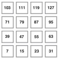
[16 LEVEL] - When [16 LEVEL] is activated, you can use the 16 pads to change a selected sound's velocity in 16 steps. When you press the [16 LEVEL] button, the last pad that was hit gets mapped to all 16 pads. The pads will now output the same note number and pressure controller as the initial pad, but
the velocity is fixed at the values shown in the diagram on the right, regardless of how hard you hit them. This allows you to have more control over the velocity of a sound.
- [NOTE REPEAT] - Holding this button while striking a pad causes the pad to retrigger at a rate based on the current Tempo and Time Division settings. The Note Repeat feature can be synced to an internal or external MIDI Clock source. [NOTE REPEAT] can function as a latching or momentary button
- [TIME DIVISION] - This button is used to specify the rate of the Note Repeat feature. When [TIME DIVISION] is activated, you can press one of the 8 switches to specify a time division. [TIME DIVISION] can function as a momentary or toggle button.
Please note that while [TIME DIVISION] is active, the 8 assignable buttons will not function as MIDI CC or Program Change switches until [TIME DIVISION] has been deactivated.
- [TAP TEMPO] - This button allows you to tap in a new tempo. If the preset is reloaded, the tempo will revert to the saved tempo value. (Please note that a preset's default tempo can be set in Edit Mode). Tap Tempo does not work when the MPD32 is set to External sync.
REAR PANEL OVERVIEW
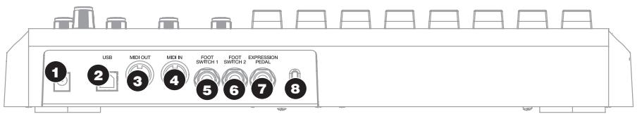
- DC POWER ADAPTER INPUT - Plug in a 6V-1A DC power adapter if you do not wish to power the MPD32 through the USB connection.
- USB CONNECTION - Plug a standard USB cable into this outlet and into the USB port of your computer. The computer's USB port will provide power to the MPD32. This connection is used to send and receive MIDI data to and from your computer and may also be used to send MIDI data from your computer to a device attached to the MIDI OUT port of the MPD32.
- MIDI OUT - Use a five-pin MIDI cable to connect the MIDI OUT of the MPD32 to the MIDI IN of an external device.
-
MIDI IN - Use a five-pin MIDI cable to connect the MIDI OUT of an external MIDI device to the MIDI IN of the MPD32.
-
FOOT SWITCH 1 - Connect a 14 TS footswitch to this input. Footswitches can be used as MIDI CC switches, or to remotely control certain features on the MPD32, such as pad triggering and button events.
- FOOT SWITCH 2 - Connect a 14 TS footswitch to this input. Footswitches can be used as MIDI CC switches, or to remotely control certain features on the MPD32, such as pad triggering and button events.
- EXPRESSION PEDAL INPUT - Connect a 1/4 TRS expression pedal to this input. We recommend using the Alesis F2 expression pedals.
- KENSINGTON LOCK - The unit may be secured to a table or surface using this Kensington Lock slot.
HOOKUP DIAGRAM
Please refer to the following scenario for connecting the MPD32.
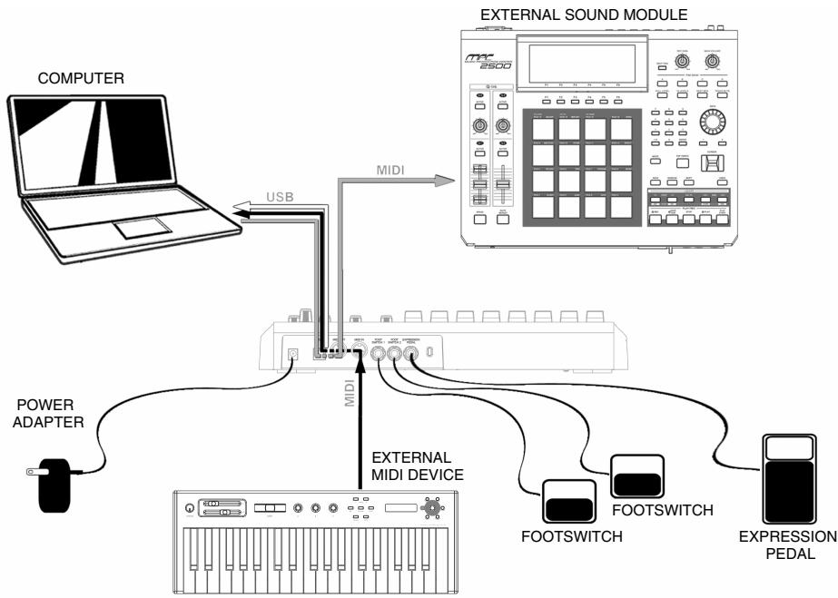

MIDI from MPD32 to computer

MIDI from external MIDI device connected to MIDI IN port of MPD32

MIDI from computer to external sound module connected to MIDOUT port of MPD32
- Connect a USB cable from your computer to the MPD32. The unit will be powered through the USB connection. Alternatively, if you do not wish to use a computer in your setup or if you wish to power the MPD32 externally, please plug in the included 6V-1A DC power adapter.
- If you would like to use an external sound module, connect a 5-pin MIDI cable from the MIDI OUT of the MPD32 to the MIDI IN of the external device.
- If you would like to use another MIDI controller in your setup, connect a 5-pin MIDI cable from the MIDI OUT of the controller to the MIDI IN of the MPD32.
- If you would like to use Footswitches or an Expression Pedal with the MPD32, connect the 1/4'' jack from the selected pedal in to the appropriate plug on the MPD32.
Since the Footswitch and Expression Pedal inputs detect whether the pedal is a "Normally Open" or "Normally Closed" type on power-on, pedals should be plugged in prior to power-on.
A NOTE ABOUT USING THE MPD32 WITH SOFTWARE
- Make sure that the MPD32 and all external devices are connected and that the USB cable is connected to your computer before opening any software applications with which you intend to use the MPD32. If the unit is not plugged in before, your software application might not recognize the MPD32 as an available device.
- In your software application, you will need to set the MPD32 as a default MIDI input device. This is usually done in the MIDI section of the Preferences menu.
- If you would like to use tempo-synced features, such as Note Repeat, you will also need to slave the MPD32 to a MIDI Clock generated by your software DAW. Make sure that your software is set up to send MIDI clock to the MPD32 and that the unit's MIDI Clock setting is set to "External" (see Global Mode). This will ensure that Note Repeat is synchronized to the tempo selected in your software DAW.
IMPORTANT
The operation of the MIDI OUT port changes depending on whether or not a USB cable is connected to the MPD32.
USB cable connected:
MIDI data from your computer is passed to the MIDI OUT port. When a USB cable is connected, you should activate "MIDI echo" in your sequencer if you want the MPD32 to control another external device.
USB cable not connected:
Whatever you play on the MPD32 is sent to the MIDI OUT port.
Note: If you have another device connected to the MPD32's MIDI IN port, that device's MIDI information will be ignored.
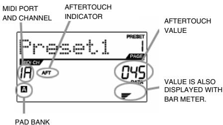
As you are working with the MPD32, the LCD will help you keep track of what values are being sent to external devices. There are several kinds of information that the MPD32 will display while in use: NOTE, AFTERTOUCH (Channel Pressure), CONTROL CHANGE, MIDI MACHINE CONTROL (MMC), and PREVIEW MODE information.
NOTE
When a PAD is hit, the MPD32 will output MIDI Note On messages to trigger sounds on your DAW or external device. Each pad can have a MIDI Note Number associated with it. When you hit a pad, the screen will display the MIDI Note Number, the MIDI Port and Channel which the pad is using, as well as the pad bank and velocity (how hard you hit the pad).
Please see 'Editing Pads'( page 12) for more information on MIDI Notes and Pads.
MIDI PORT
AND CHANNEL
NOTE
INDICATOR
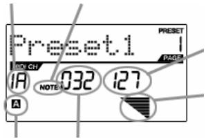
PAD BANK
MIDI NOTE
NUMBER
NOTE
VELOCITY
VELOCITY IS
ALSO DISPLAYED
WITH BAR METER.
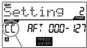
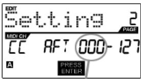
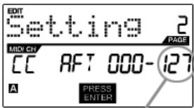
NOTE AFTERTOUCH (Channel Pressure)
When enabled, AFTERTOUCH is MIDI data sent when pressure is applied to one of the pads after it has been struck and while it is being held down. Aftertouch will be displayed on the far right of the display as you apply pressure to the pad.
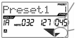
AFTERTOUCH
VALUE
AFTERTOUCH
VALUE IS ALSO
DISPLAYED WITH
BAR METER
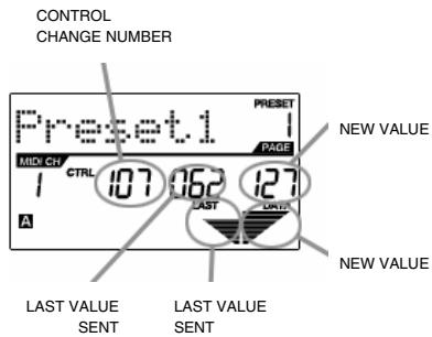
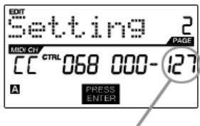
CONTROL CHANGE
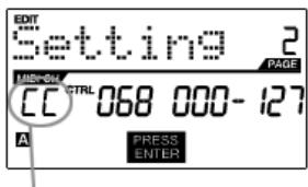
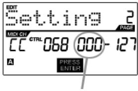
When a KNOB or FADER is used, the MPD32 will output MIDI Control Change data. This data is used to control parameters on your DAW or external sound module. When you move a knob or fader, the screen will indicate the Control Change (CC) Number, value, and MIDI Channel.
Please see 'Editing Knobs and Faders' (page 15) for more information on Control Change.
MIDI PORT
AND CHANNEL
CONTROL CHANGE
INDICATOR
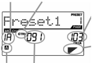
CONTROL CHANGE
VALUE
PAD BANK
CONTROL CHANGE
NUMBER
VALUE IS ALSO
DISPLAYED WITH
BAR METER.
CONTROL AFTERTOUCH
The knobs and faders on the MPD32 can also be set to transmit AFTERTOUCH information.
Please see 'Editing Knobs and Faders' (page 15) for more information on setting knobs and faders to transmit Aftertouch.
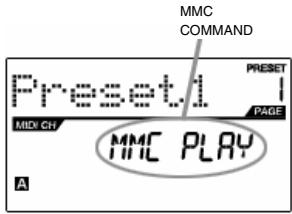
MIDI MACHINE CONTROL COMMAND (MMC)
MIDI MACHINE CONTROL (MMC) is commonly used to send transport control messages to hardware record or playback machines. For example, pressing [PLAY] on the MPD32 sends an MMCPLAY message to a connected multi-track recorder, which begins playing. When you press [STOP] on the MPD32, the deck also stops.
PREVIEWING
When the [PREVIEW] button is held down, and a fader or knob is moved, the LCD displays the screen on the right. The display shows the assigned event and the last sent value of moved knob or fader. While the [PREVIEW] button is held, the fader of knob will not be transmitting any information until [PREVIEW] is released and the fader or knob is used again. At that point, the fader or knob will begin transmitting from the value selected in the New Value field while in Preview mode.
THE ADVANTAGES OF PREVIEWING
The [PREVIEW] button allows you to see what value will be sent by a controller, without actually sending the value. This gives you precise control over your parameters and helps avoid erroneous controller data being sent to your devices due to the physical position of the controller. For example, imagine that fader S1 is being used to send three different MIDI CC numbers, depending on the control bank which you are currently in. Let's assume that S1 is assigned to MIDI CC#10 in control bank A and MIDI CC#11 in control bank B. While in control bank A, you adjust S1 (MIDI CC#10) to a value of 40. Now you switch over to control bank B and adjust S1 (MIDI CC#11) to a value of 80. If you now switch back to control bank A and try to adjust S1 (MIDI CC#10), you will notice that the transmitted values will begin at 80 (instead of 40), due to the physical location of the fader. To prevent these jumps in control values, you can hold down [PREVIEW] and move S1 back to a value of 40 (which will be shown in the "Last" value readout on the display). The fader will not be transmitting information while the [PREVIEW] button is held down. Once you reset the fader back to its "Last" value, you can release the [PREVIEW] button. Adjusting S1 (MIDI CC#10) will now give you a nice starting point at a value of 40.
ABOUT MODES
The MPD32 has four different modes of operation. Each mode can be accessed by pressing its corresponding button. Following is a short description of each mode:
Preset Mode
| PRESET | This mode allows you to load, save and copy Presets. A Preset is a collection of information about how different faders, knobs, and pads will behave. Using Presets allows you to save different configurations so you can quickly load them when you need them, without having to reprogram the MPD32 every time. (page 9) |
| Edit Mode | |
| EDIT | This mode allows you to edit the configuration of the MPD32. Edit Mode is a powerful tool for customizing your set-up. In this mode, you can make changes to how the pads, knobs and faders are behaving. For example, you may wish to have a fader or a knob transmit only a limited range of MIDI data, or you may wish to have a pad that transmits on a different MIDI Channel. You can change these and various other parameters in Edit Mode. (page 10) |
| Global Mode | |
| GLOBAL | This mode allows you to set global parameters and make general changes to how your MPD32 is functioning. The parameters that you can modify in Global Mode include Controller Resets, Pad Velocity Curves, Pad Threshold, MIDI Clock options, Display Brightness, and more. (page 27) |
| Program Change Mode | |
| PROGRAM CHANGE | This mode allows you to transmit various Program Change messages. In this mode, you can remotely switch between different programs on your DAW or external device directly from the MPD32. (page 31) |
PRESET MODE
What is a Preset?
A Preset is a collection of information about how the MPD32's faders, knobs and pads will behave. Using Presets allows you to save different configurations so you can quickly load them when you need them, without having to reprogram the MPD32 every time.
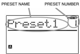
The MPD32 features different Preset banks which you can load and write to. When you turn on the MPD32, it will automatically go into Preset Mode and Preset 1 will be displayed on the screen. You can also press the [PRESET] button at any time to call up this mode. In Preset Mode you can load, save/copy and rename Presets - each of these functions can be accessed through the 3 different pages. You can navigate between these pages with the [< ] and [>] buttons.
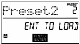
PAGE 1 - LOAD PRESET
- While you are in Preset Mode, you can change Presets with the [VALUE] dial below the screen. Turning the dial increments or decrements the current Preset number and displays the screen on the right:
When you do this, you will notice that 'PRESS ENTER' will begin to blink.
- Pressing [ENTER] loads the selected Preset. Pressing [<] or [PRESET] cancels the operation.
PAGE 2 - SAVE/COPY PRESET
In Preset Mode, you can save any changes that you have made to the current Preset or copy the Preset to a new location.
Note that if you are saving the Preset to the same location (same preset number) the screen will say 'SAVE TO' and if you are saving to a different location (different preset number), the screen will display 'COPY TO'.
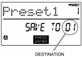
- While you are in Preset Mode, press [>] until you see a screen similar to the one shown above.
- You can select the location where you wish to save the Preset by turning the [VALUE] knob.
When you do this, you will notice that the 'PRESS ENTER' segment will begin to blink.
- Press [ENTER] to save the Preset to the selected destination. Pressing [<] or [PRESET] cancels the operation.
PAGE 3 - NAME PRESET
While you are in Preset Mode, you can also change the Preset name. This way you can assign specific names to different Presets so you can quickly identify and access different controller configurations.
- To name or rename the Preset, press [>] until you see 'Preset Name' displayed on the screen.
You will notice that the first letter of the name will begin blinking.
- Turn the [VALUE] dial to change the blinking character.
- To move between the characters, use [<] and [>] .
- When done, press [PRESET] again to save.
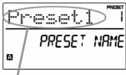
ENTER PRESET NAME IN THIS FIELD
EDIT MODE
Pressing [EDIT] calls up Edit Mode. In this mode, you can edit the settings of the currently selected Preset. The settings vary depending on the controller you are editing and are described below.
Please note that the changes you make will only apply to the currently selected Preset.
Also note that if you wish to save the changes made in Edit Mode, you will need to save the current preset.
NAVIGATING EDIT MODE
- Press [EDIT] to enter Edit Mode.
- To select the controller you wish to edit, simply engage it - this will prompt the screen to display the available event types for the particular controller (Page 1).
- If there are multiple event types for the selected controller, turn the [VALUE] dial to select the desired event type. Press [ENTER] to view the parameters of the selected event type, if available (Page 2).
- To move between the parameter fields on Page 2, use [<] and [>] . To change the values of the fields, turn the [VALUE] dial.
- When finished editing the controller, press [ENTER] to accept the change or press [<] to cancel.
You can use the example screenshot on the right to help you determine where the Page 2 parameters described on the following page will appear on the screen.
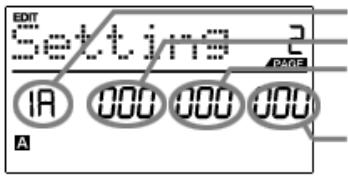
FIELD 1
FIELD 2
FIELD 3
FIELD 4
EDIT MODE PARAMETERS
| CONTROLLER | PAGE 1 (EVENT TYPE) | PAGE 2 (PARAMETERS) |
| PADS | NOTE | MIDI CHANNEL (field 1)
NOTE NUMBER (field 2)
PLAY MODE (field 3)
PRESSURE BEHAVIOR (field 4) |
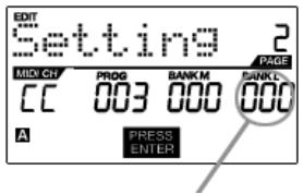
| PROGRAM CHANGE | MIDI CHANNEL (field 1)
PROGRAM CHANGE NUMBER (field 2)
BANK M (MSB) (field 3)
BANK L (LSB) (field 4) |
| KNOBS AND FADERS | CONTROL CHANGE | MIDI CHANNEL (field 1)
CC NUMBER (field 2)
RANGE - MINIMUM VALUE (field 3)
RANGE - MAXIMUM VALUE (field 4) |
| AFTERTOUCH | MIDI CHANNEL (field 1)
CC NUMBER (field 2)
RANGE - MINIMUM VALUE (field 3)
RANGE - MAXIMUM VALUE (field 4) |
| BUTTONS | CONTROL CHANGE | MIDI CHANNEL (field 1)
CC NUMBER (field 2)
BUTTON MODE (field 4) |
| PROGRAM CHANGE | MIDI CHANNEL (field 1)
PROGRAM CHANGE NUMBER (field 2)
BANK M (MSB) (field 3)
BANK L (LSB) (field 4) |
| ARP ON/OFF | TYPE/RANGE/TOGGLE | ARPEGGIO TYPE (field 2)
ARPEGGIO RANGE (field 3)
ARPEGGIO TOGGLE BEHAVIOR (field 4) |
| GATE/SWING | ARPEGGIO GATE VALUE (field 2)
ARPEGGIO SWING VALUE (field 4) |
| NOTE REPEAT | TOGGLE/MOMENTARY | BUTTON MODE (field 2) |
| GATE/SWING | NOTE REPEAT GATE VALUE (field 2)
NOTE REPEAT SWING VALUE (field 4) |
| TIME DIVISION | DIVISION | DEFAULT TIME DIVISION (field 2)
BUTTON MODE (field 4) |
| TRANSPORT | TRANSPORT FUNCTION | MMC, MIDI, MMC/MIDI, or CTRL (field 2) |
| TAP TEMPO | TEMPO | BPM (field 2) |
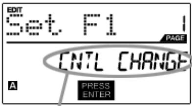
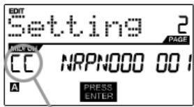
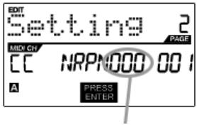
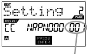
| EXPRESSION PEDAL | CNTL CHANGE | MIDI CHANNEL (field 1)
CC NUMBER (field 2)
RANGE - MINIMUM VALUE (field 3)
RANGE - MAXIMUM VALUE (field 4) |
| AFTERTOUCH | MIDI CHANNEL (field 1)
CC NUMBER (field 2)
RANGE - MINIMUM VALUE (field 3)
RANGE - MAXIMUM VALUE (field 4) |
| FOOTSWITCH | MIDI CC | MIDI CHANNEL (field 1)
CC NUMBER (field 2)
BUTTON MODE (field 4) |
| DRUM PAD | PAD NUMBER (field 4) |
| NOTE REPEAT | |
| TIME DIV |
| TAP TEMPO |
| BANK CHANGE |
| PLAY/STOP |
| PLAY/RECORD |
| SUSTAIN |
EDITING THE PADS
The pads on the MPD32 can be set to transmit Note or Program Change information when they are hit. The default operation of the pads is set to Note, which means that the pad will generate Note On/Off messages to trigger sounds. The pads may also be set up to transmit Program Change information, which allows you to use the pads to switch to different programs (instruments or sound banks) on your DAW or external device. If you would like to know more about Program Change, please read 'Program Change Mode' on page 29.
What is a Note Message?
A Note Message is a MIDI message that tells an instrument to play a note. More generally, this means that Note Messages are used to start and stop sounds. When you press one of the pads, a 'Note On' message is sent to your DAW or external device. This toggles a note or sample. When you release the pad, a 'Note Off' message is sent. This message will stop the note or sample.
What is a Program Change?
A Program Change Message tells your DAW or external device to switch to a new program. Most often, these programs are collections of samples or instruments.
For more information, see 'Program Change Mode' on page 29.
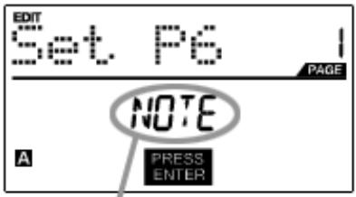
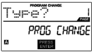
SELECT PAD EVENT TYPE IN THIS FIELD.
- Press [EDIT] to enter EDIT MODE.
- Press the pad which you would like to edit.
- On Page 1, turn the [VALUE] dial to select 'NOTE' or 'PROG CHANGE' (Program Change) as the event type.
- Press [ENTER] to view Page 2.
Depending on which event type you select on Page 1, parameter options on Page 2 will be different.
- Use [<] and [>] buttons to move through fields on the second page.
The parameter fields available for each event type are outlined in the following pages.
NOTE PARAMETERS
The following list of parameters can be accessed if the pad event type is set to Note.
MIDI CHANNEL FIELD
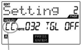
MIDI PORT/CHANNEL FIELD
This field sets the MIDI Port and Channel which the pad will use to transmit messages. You can assign pads to one of two MIDI Ports, A or B, and to one of 16 MIDI Channels on each port (i.e. B11). You may also assign the pad to the MIDI Common Channel.
- Press [<] to select MIDI Port/Channel field.
- While in MIDI Port/Channel field, use [VALUE] dial to select desired MIDI Port and Channel.
- Press [> to select the next field.
Note: When not used via USB, only pads assigned to port A will transmit MIDI information via the 5-pin MIDI port on the back of the MPD32.
NOTE FIELD
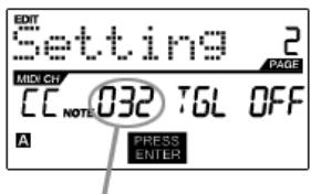
NOTE FIELD
This field sets the MIDI Note Number that the pad will transmit when it is hit.
- Use [<] or [>] to select Note field.
- While in MIDI Port/Channel field, use [VALUE] dial to select desired MIDI Port and Channel.
- Press [>] to select the next field.
Note: Software modules or drum machines are often programmed to trigger sounds based on specific Note Numbers associated with each sample. You may have to experiment setting different Note Numbers on the MPD32 to find the range that is suited for your application.
PLAY MODE FIELD
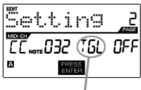
PLAY MODE FIELD
Here, you can select whether the pad transmits Note On/Off information in a standard momentary (MTY) way like a keyboard, where hitting the pad generates a Note On and releasing it a Note Off message, or in a toggle (TGL) way where the first hit of the pad outputs a Note On, the second hit transmits a Note Off.
- Use [<] or [>] to select Play Mode field.
- While in Play Mode field, use [VALUE] dial to select desired Play Mode.
- Press [>] to select the next field.
PRESSURE FIELD
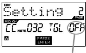
PRESSURE FIELD
Here, you can set the pad to transmit pressure information as a channel pressure message (CPR) or polyphonic pressure message (PPR).
- Press [> to select Pressure field.
- While in Pressure field, use [VALUE] dial to select "OFF", "CPR", or "PPR".
When finished editing, press [ENTER] to save or [<] to cancel the changes.
PROGRAM CHANGE PARAMETERS
The following list of parameters can be accessed if the pad event type is set to Program Change.
MIDI CHANNEL FIELD
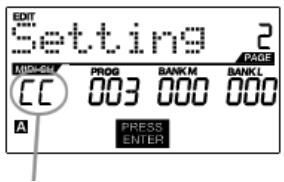
MIDI PORT/CHANNEL FIELD
Program Change messages can be sent on one of two MIDI Ports, A or B, and one of 16 MIDI Channels on each port (i.e. A7). You may also assign Program Change to use the MIDI Common Channel.
- Use the [<] button to select MIDI Port/Channel field.
- While in MIDI Port/Channel field, use [VALUE] dial to select desired MIDI Port and Channel.
- Use the [> button to select the next field.
PROGRAM CHANGE FIELD
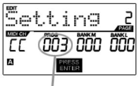
PORGRAM CHANGE FIELD
In this field you can set which Program Change Number the pad will transmit when it is pressed.
- Use [<] or [>] buttons to select Program Change field.
- While in Program Change field, use [VALUE] dial to select desired Program Change Number.
- Use the [> button to select the next field.
BANK M FIELD
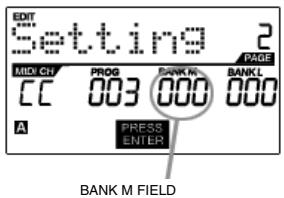
Bank M describes the Most Significant Bit (MSB) of information.
- Use [<] or [>] buttons to select Bank M field.
- While in Bank M field, use [VALUE] dial to select desired value.
- Use the [>] button to select the next field.
BANK L FIELD
BANK L FIELD
Bank L describes the Least Significant Bit (MSB) of information.
- Use the [<] or [>] buttons to select Bank L field.
- While in Bank L field, use [VALUE] dial to select desired value.
Note:
You can also configure pads to send Program Change messages only, without specifying Bank M and Bank L. While editing Bank M and Bank L fields of a pad, use [VALUE] dial to set Bank M and Bank L to 'OFF' (beyond 000). This will cause the pad to transmit only a Program Change message.
When finished editing, press [ENTER] to save or [ ] to cancel the changes.
EDITING KNOBS, FADERS AND EXPRESSION PEDAL
The knobs, faders and expression pedal input on the MPD32 can be set to transmit Control Change or Aftertouch information. In addition, the endless knobs may also be assigned as an Increment/Decrement function. The default operation of knobs, faders and expression pedal input is to transmit Control Change information.
What is Control Change?
Control Change refers to the use of MIDI Continuous Controller data. Continuous Controller (CC) data are MIDI messages capable of transmitting a range of values, usually 0-127. CC's are commonly used for controlling volume, pan, and other parameters on your DAW or sound module.
What is Aftertouch?
Aftertouch refers to MIDI data sent when pressure is applied to a pad after it has been struck and while it is being held down. Aftertouch is often used to control vibrato, volume, and other parameters.
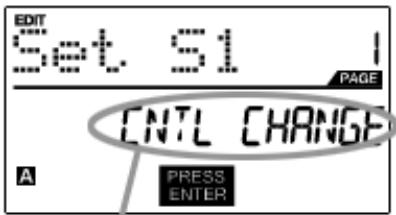
SELECT EVENT TYPE IN THIS FIELD.
- Press [EDIT] to enter EDIT MODE.
- Move the fader, turn the knob or press down on the expression pedal.
- On Page 1, turn the [VALUE] dial to select 'CTRL CHANGE' (Control Change) or 'AFTERTOUCH' as the event type.
- Press [ENTER] to view Page 2.
Depending on which event type you select on Page 1, parameter options on Page 2 will be different.
- Use [<] and [>] to move through fields on the second page.
The parameter fields available for each event type are outlined in the following pages.
Please note that for the purposes of this text, the expression pedal input is considered a fader (F9).
CONTROL CHANGE PARAMETERS
The following list of parameters can be accessed if the event type for the knob or fader is set to Control Change.
MIDI CHANNEL FIELD
MIDI PORT/CHANNEL FIELD
This field sets the MIDI Port and Channel which the knob or fader will use to transmit messages. You can assign knobs and faders to one of two MIDI Ports, A or B, and to one of 16 MIDI Channels on each port (i.e. A14). You can also assign a knob or fader to use the MIDI Common Channel.
- Press [<] to select MIDI Port/Channel field.
- While in MIDI Port/Channel field, use [VALUE] dial to select desired MIDI Port and Channel.
- Press [>] to select the next field.
Note: When not used via USB, only knobs and faders assigned to port A will be transmitted via the 5-pin MIDI port on the back of the MPD32.
CONTROL CHANGE FIELD

CONTROL CHANGE FIELD
In this field you can set which MIDI CC # the knob or fader will transmit when it is used.
- Use [<] or [>] to select Control Change field.
- While in Control Change field, use [VALUE] dial to select desired Control Change Number.
- Press [>] button to select the next field.
Note: To control a parameter in your DAW or sound module with a knob or fader, both the parameter and the physical controller should be set to the same Controller Number.
MINIMUM RANGE FIELD
MINIMUM RANGE FIELD
This field is used to specify the minimum value that the knob or fader can output.
- Use [<] or [>] to select Minimum Range field.
- While in Minimum Range field, use [VALUE] dial to select desired minimum value.
- Press [>] button to select the next field.
Tip: Sometimes you might not want the full 0-127 range of control that a fader automatically defaults to. Often, reducing the value range of the fader might give you more precise control over the parameter it is controlling. For example, if you are using one of the faders to control a synchronized delay line, there might only be about 10 available values for the sync delay time (1/2, 1/4, 1/8 note, etc.). Therefore, it wouldn't make much sense to have the fader transmit the full 128 MIDI control values, since this only gives you a tenth of the full fader range. Instead, try setting the maximum value of that fader to 10.
MAXIMUM RANGE FIELD
MAXIMUM RANGE FIELD
This field is used to specify the maximum value that the knob or fader can output.
- Use the [<] or [>] buttons to select Maximum Range field.
- While in Maximum Range field, use [VALUE] dial to select desired maximum value.
Tip: Setting the maximum value of a controller lower than the minimum value will cause the knob or fader to behave inversely. For example, if you are controlling an interface or plug-in that operates with a drawbar structure, such as organ instruments, it might be more intuitive to invert your faders.
AFTERTOUCH PARAMETERS
For some applications, you might wish to use the faders or knobs as Aftertouch controllers. In this scenario, the knob or fader will transmit Aftertouch information which could be used to control, say, vibrato or tremolo. The following list of parameters can be accessed if "Aftertouch" is selected as the event type for the knob or fader.
MIDI CHANNEL FIELD
MIDI PORT/CHANNEL FIELD
This field sets the MIDI Port and Channel which the knob or fader will use to transmit messages. You can assign knobs and faders to one of two MIDI Ports, A or B, and to one of 16 MIDI Channels on each port (i.e. A14). You can also assign a knob or fader to use the MIDI Common Channel.
- Press [<] to select MIDI Port/Channel field.
- While in MIDI Port/Channel field, use [VALUE] dial to select desired MIDI Port and Channel.
- Press [> to select the next field.
Note: When not used via USB, only knobs and faders assigned to port A will be transmitted via the 5-pin MIDI port on the back of the MPD32.
MINIMUM RANGE FIELD
MINIMUM RANGE FIELD
This field is used to specify the minimum value that the knob or fader can transmit.
- Use [<] or [>] buttons to select Minimum Range field.
- While in Minimum Range field, use [VALUE] dial to select desired minimum aftertouch value.
- Use the [>] button to select the next field.
MAXIMUM RANGE FIELD
MAXIMUM RANGE FIELD
This field is used to specify the maximum value that the knob or fader can transmit.
- Use the [<] or [>] buttons to select Maximum Range field.
- While in Maximum Range field, use [VALUE] dial to select desired maximum value.
When finished editing, press [ENTER] to save or [<] to cancel the changes.
INIncrement/DECREMENT PARAMETERS (knobs only)
The endless knobs on the MPD32 may also be used as an increment/decrement NRPN function. This allows you to use the knob to increment and decrement through parameters as opposed to sending an absolute value. Please note that the implementation of NRPN functions depends strictly on the software with which you will be using the MP49. Consult your software's documentation to find out how NRPN functions are supported.
MIDI CHANNEL FIELD
MIDI PORT/CHANNEL FIELD
This field sets the MIDI Port and Channel which the knob will use to transmit messages. You can assign the knobs to one of two MIDI Ports, A or B, and to one of 16 MIDI Channels on each port (i.e. A14). You can also assign knobs to use the MIDI Common Channel.
- Press [<] to select MIDI Port/Channel field.
- While in MIDI Port/Channel field, use [VALUE] dial to select desired MIDI Port and Channel.
- Press [> to select the next field.
Note: When not used via USB, only knobs assigned to port A will be transmitted via the 5-pin MIDI port on the back of the MPD32.
BANK M FIELD
BANK M FIELD
Bank M describes the Most Significant Bit (MSB) of information.
- Use [<] or [>] buttons to select Bank M field.
- While in Bank M field, use [VALUE] dial to select desired value.
- Use the [>] button to select the next field.
BANK L FIELD
BANK L FIELD
Bank L describes the Least Significant Bit (MSB) of information.
- Use the [<] or [>] buttons to select Bank L field.
- While in Bank L field, use [VALUE] dial to select desired value.
When finished editing, press [ENTER] to save or [<] to cancel the changes.
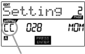
The buttons on the MPD32 can be used to transmit Control Change or Program Change information.
SELECT BUTTON EVENT TYPE IN THIS FIELD.
- Press [EDIT] to enter EDIT MODE.
- Press the button you would like to edit.
- On Page 1, turn the [VALUE] dial to select 'CTRL CHANGE' (Control Change) or 'PROG CHANGE' (Program Change) as the event type.
- Press [ENTER] to view Page 2. Depending on which event type you select on Page 1, parameter options on Page 2 will be different.
- Use [< ] and [>] buttons to move through the fields on the second page.
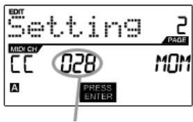
CONTROL CHANGE PARAMETERS
The following list of parameters can be accessed if "Control Change" is selected as the event type for the selected button.
MIDI CHANNEL FIELD
MIDI PORT/CHANNEL FIELD
This field sets the MIDI Port and Channel which the button will use to transmit messages. You can assign the button to one of two MIDI Ports, A or B, and to one of 16 MIDI Channels on each port (i.e. A14). You can also assign the button to use the MIDI Common Channel.
- Press [] to select MIDI Port/Channel field.
- While in MIDI Port/Channel field, use [VALUE] dial to select desired MIDI Port and Channel.
- Press [> ] button to select the next field.
Note: When not used via USB, only buttons assigned to port A will be transmitted via the 5-pin MIDI port on the back of the MPD32.
CONTROL CHANGE FIELD
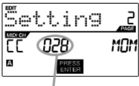
CONTROL CHANGE FIELD
In this field you can set which Control Change Number the button will transmit when it is pressed.
- Use [<] or [>] to select Control Change field.
- While in Control Change field, use [VALUE] dial to select desired Control Change Number.
- Press [> ] button to select the next field.
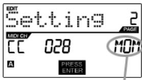
PLAY MODE

PLAY MODE FIELD
Here, you can select whether the button transmits MIDI CC information in a momentary (MOM) way, where pressing the button outputs 127 and releasing it transmits 0, or in a toggle (TGL) way where the first press outputs 127 and the second press transmits 0.
- Press [> to select Play Mode field.
- While in Play Mode field, use [VALUE] dial to select desired Play Mode.
When finished editing, press [ENTER] to save or [<] to cancel the changes.
PROGRAM CHANGE PARAMETERS
Buttons can also be assigned to transmit Program Change messages when pressed. The following list of parameters can be accessed if the button event type is set to "Program Change".
MIDI CHANNEL FIELD
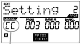
MIDI PORT/CHANNEL FIELD
Buttons can send Program Change messages can be sent on one of two MIDI Ports, A or B, and one of 16 MIDI Channels on each port (i.e. A7). You may also assign Program Change to use the MIDI Common Channel.
- Press [<] to select MIDI Port/Channel field.
- While in MIDI Port/Channel field, use [VALUE] dial to select desired MIDI Port and Channel.
- Press [> to select the next field.
PROGRAM CHANGE FIELD
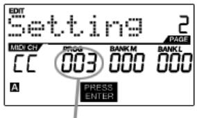
PORGRAM CHANGE FIELD
In this field you can set which Program Change Number the button will transmit when it is pressed.
- Press [<] or [>] to select Program Change field.
- While in Program Change field, use [VALUE] dial to select desired Program Change Number.
- Press [> to select the next field.
BANK M FIELD
BANKMFIELD
Bank M describes the Most Significant Bit (MSB) of information.
- Press [<] or [>] to select Bank M field.
- While in Bank M field, use [VALUE] dial to select desired value.
- Press [>] to select the next field.
BANK L FIELD
BANK L FIELD
Bank L describes the Least Significant Bit (MSB) of information.
- Press [<] or [>] to select Bank L field.
- While in Bank L field, use [VALUE] dial to select desired value.
Note:
You can also configure buttons to send Program Change messages only, without specifying Bank M and Bank L. While editing Bank M and Bank L fields, use [VALUE] dial to set Bank M and Bank L to 'OFF' (beyond 000). This will cause the button to transmit only a Program Change message.
EDITING NOTE REPEAT
The MPD32 features the Note Repeat function, which can be found on our legendary Music Production Center (MPC) models. With Note Repeat enabled, you can repeatedly trigger a sound by simply holding down a pad. The sound will be retriggered at a rate equivalent to the currently selected Time Division. With the Note Repeat feature, you can record a phrase that would be difficult to record in real time, such as 16 beat hi hat, snare roll, etc...
The following Note Repeat settings may be edited:
BUTTON MODE (TOGGL/MOTRY) - This describes whether the [NOTE REPEAT] button functions in a momentary or toggle fashion.
GATE - The gate parameter describes the duration of the repeated notes.
SWING - The swing parameter describes the swing offset for the even notes in the repeated sequence.
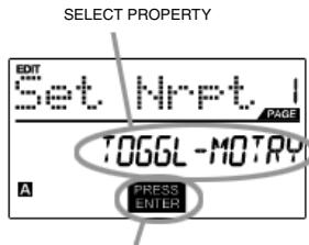
PRESS ENTER TO EDIT
- To edit Note Repeat, press [EDIT] to enter Edit Mode.
- Now select Note Repeat for editing by pressing [NOTE REPEAT].
- You will see Page 1 displayed on the screen (shown on the left).
- Turn the [VALUE] dial to select the property you wish to edit - (Toggl-Motry) or (Gate Swing).
- Press [ENTER] to edit the selected property.
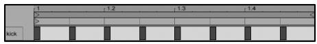
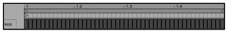
Please refer to the following illustrations to help you understand how Note Repeat parameters affect the triggered sequence:
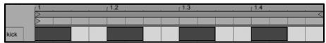

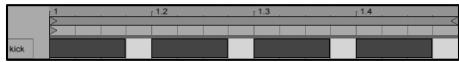

Let's take the kick drum sequence shown on the left as an example. This sequence was generated with the Note Repeat feature with a Time Division setting of 1/4 note.
Now, if we decrease the Gate parameter, the sequence will look like this.
Conversely, if we increase the Gate parameter, the sequence will look like this.
Now, if we were to add some swing to our original sequence, we will end up with a sequence like this. Notice how each even note in the sequence is being pushed back in time to create the swing effect. If we keep increasing the Swing value, these notes will occur closer and closer to the odd notes.
Please note:
For the Gate effect to be perceived, the sounds you are triggering need to have a long decay.
The following screen will appear if you select "TOGGL-MOTRY" on Page 1. In this field, you can select whether the [NOTE REPEAT] button will behave in a momentary (MTY) fashion, where pressing the button turns on the Note Repeat function and releasing it turns it off, or in a toggle (TGL) manner, where pressing the button turns on the Note Repeat function and pressing again turns it off.
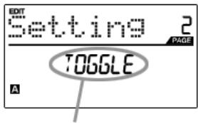
BUTTON MODE
- While in Button Mode field, use [VALUE] dial to select Button Mode (Toggle or Momentary).
- Press [ENTER] to accept change.
NOTE REPEAT PARAMETERS - GATE, SWING
The following parameters can be adjusted if you select "GATE SWING" on Page 1.
GATE
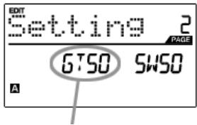
GATE FIELD
Select the Note Repeat Gate in this field.
- While in Gate field, use [VALUE] dial to select Gate duration.
- Use the [>] button to select the next field.
SWING
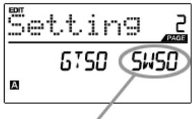
SWING FIELD
Select the Note Repeat Swing in this field.
- Use the [>] button to select the Swingfield
- While in Swing field, use [VALUE] dial to select the desired Swing value.
- Press [ENTER] to accept changes.
EDITING TIME DIVISION
The Time Division feature works in conjunction with Note Repeat. When Note Repeat is enabled and a pad is held down, the MPD32 will output notes at a rate equivalent to the Time Division setting. To change to a new Time Division setting, press [TIME DIVISION] and select a new rate by pressing its corresponding button (1/4, 1/4T, 1/8, etc.).
Please refer to the following illustrations to better understand how the Time Division feature works with Note Repeat:
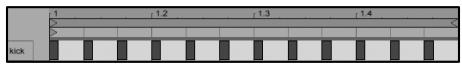

With an 1/8 note Time Division setting, the sequence will look like this.
With an 1/8T note Time Division setting, the sequence will look like this.
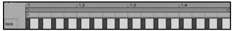
With a 1/16 note Time Division setting, the sequence will look like this.
With a 1/16T note Time Division setting, the sequence will look like this.
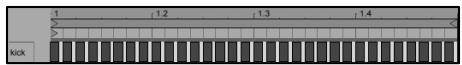
With a 1/32 note Time Division setting, the sequence will look like this.
With a 1/32T note Time Division setting, the sequence will look like this.
The following Time Division settings may be edited:
DEFAULT DIVISION - Describes the default time division which will be set when the current Preset is loaded. BUTTON MODE (TOGGL/MOTRY) - Describes whether the [TIME DIVISION] button functions in a momentary or toggle fashion.

PRESS ENTER TO EDIT
- To edit Time Division settings, press the [EDIT] button to enter Edit Mode.
- Now select Time Division for editing by pressing [TIME DIVISION].
- You will see Page 1 displayed on the screen (shown on the left).
- Press [ENTER] to edit the Time Division settings.
DEFAULT TIME DIVISION
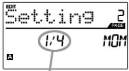
DEFAULT DIVISION FIELD
Each Preset can have a default Time Division setting which is set every time the Preset is loaded.
- While in Default Time Division field, use [VALUE] dial to select the default Time Division (1/4, 1/4T, 1/8, etc.)
- Press [>] to select the next field.
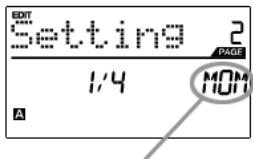
BUTTON MODE FIELD
In this field, you can select whether the [TIME DIVISION] button will behave in a momentary (MTY) fashion, where pressing the button will turn on the Time Division function and releasing it will turn it off, or in a toggle (TGL) manner, where pressing the button turns on the Time Division function and pressing again turns it off.
- Press [> to select Button Mode field.
- Turn [VALUE] dial to select the Button Type.
EDITING TRANSPORT CONTROL
The MPD32 can be configured to send transport control information in a variety of ways: MMC (MIDI Machine Control), MMC/MIDI, MIDI, or CTRL. Some applications and devices have dedicated MMC functions and will only respond to MMC messages, while others may not have reserved MMC functions but implement transport control via MIDI SysEx or MIDI CC messages. To account for these scenarios, we have provided a way to edit the messages sent by the transport control buttons. This allows you to customize the MPD32's transport to work with your application or external device.

PRESS ENTER TO EDIT
- To edit transport control settings, press [EDIT] to enter Edit Mode.
- Now select the transport control for editing by pressing [<<] , [>>] , [STOP], [PLAY], or [REC].
- You will see Page 1 displayed on the screen (shown on the left).
- Press [ENTER] to edit transport control settings.
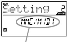
TRANSPORT CONTROLMESSAGE FORMAT
- When on Page 2, use the [VALUE] dial to select the format of the transport control messages (MMC, MMC/MIDI, MIDI, CTRL).
- Press [ENTER] to accept the change or [<] to cancel.
EDITING TAP TEMPO
Each Preset on the MPD32 can have a default tempo associated with it. Every time that the Preset is loaded, the BPM setting will be loaded automatically.
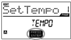
PRESS ENTER TO EDIT
- To edit the default tempo, press [EDIT] to enter Edit Mode.
- Now select tempo for editing by pressing [TAP TEMPO].
- You will see Page 1 displayed on the screen (shown on the left).
- Press [ENTER] to edit the default tempo for the current Preset.
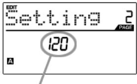
BPM FIELD
- On Page 2, use the [VALUE] dial to adjust the default tempo.
- Press [ENTER] to accept the change or [<] to cancel.
The two footswitch inputs on the rear of the MPD32 can be used in a variety of different ways. For example, footswitches can be used as conventional MIDI CC switches. In addition, footswitches can also be used to trigger specific pads on the top panel (for example, to play out a kick drum sequence). Lastly, the footswitch inputs can be used to remotely enable and disable specific functions on the MPD32, such as Note Repeat, Time Division, Tap Tempo, Bank Change, Play/Stop, Play/Record or Sustain.
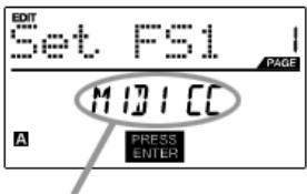
SELECT FOOTSWITCH EVENT TYPE
- To edit footswitch input settings, press [EDIT] to enter Edit Mode.
- Now select the footswitch you would like to edit by pressing it down.
- You will see Page 1 displayed on the screen (shown on the left).
- Select the event type for the footswitch by turning the [VALUE] dial.
- Press [ENTER] to accept change and view page 2 parameters, if available.
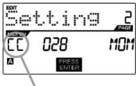
CONTROL CHANGE PARAMETERS
The following parameters can be accessed is you select "Control Change" as the footswitch event type.
MIDI CHANNEL FIELD
MIDI PORT/CHANNEL FIELD
This field sets the MIDI Port and Channel which the footswitch will use to transmit messages. You can assign the footswitch to one of two MIDI Ports, A or B, and to one of 16 MIDI Channels on each port (i.e. A14). You can also assign the footswitch to use the MIDI Common Channel.
- Press [<] to select MIDI Port/Channel field.
- While in MIDI Port/Channel field, use [VALUE] dial to select desired MIDI Port and Channel.
- Press [> ] button to select the next field.
Note: When not used via USB, only footswitches assigned to port A will be transmitted via the 5-pin MIDI port on the back of the MPD32.
CONTROL CHANGE FIELD
CONTROL CHANGE FIELD
In this field you can set which Control Change Number the button will transmit when it is pressed.
- Use [<] or [>] to select Control Change field.
- While in Control Change field, use [VALUE] dial to select desired Control Change Number.
- Press [>] button to select the next field.
PLAY MODE
PLAY MODE FIELD
Here, you can select whether the footswitch transmits MIDI CC information in a momentary (MOM) way, where pressing the footswitch outputs 127 and releasing it transmits 0, or in a toggle (TGL) way where the first press outputs 127 and the second press transmits 0.
- Press [> to select Play Mode field.
- While in Play Mode field, use [VALUE] dial to select desired Play Mode.
DRUM PAD PARAMETERS
If you choose "Drum Pad" as the event type for the footswitch, page 2 allows you to select which pad will be triggered with the footswitch.
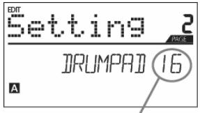
DRUM PAD NUMBER
- Turn [VALUE] dial to select the desired pad.
- Press [ENTER] to accept the setting or [<] to cancel.
OTHER FUNCTIONS
As we mentioned previously, footswitches may also be used to engage and disengage specific functions on the MPD32. Simply select which function you would like to control with the footswitch:
NOTE REPEAT - footswitch will turn Note Repeat feature on and off.
TIME DIV - footswitch will enable and disable Time Division.
TAP TEMPO - footswitch will work as a Tap Tempo button.
BANK CHANGE - footswitch will cycle through the 3 different control banks.
PLAY/STOP - footswitch will be used as a Start / Stop button.
PLAY/RECORD - footswitch will be used as a Play / Record button.
GLOBAL MODE
In Global Mode, you can send global messages and make general changes to the way that your MPD32 functions. Global Mode options are organized under different pages and include the list of options shown on the right:
To enter Global Mode, press the [GLOBAL] button. To scroll through the different pages, use [<] and [>] .
| KILL MIDI | Page 1 |
| MIDI COMMON CHANNEL | Page 2 |
| LCD CONTRAST | Page 3 |
| PAD SENSITIVITY | Page 4 |
| PAD VELOCITY CURVE | Page 5 |
| PAD THRESHOLD | Page 6 |
| MIDI CLOCK | Page 7 |
| TAP TEMPO AVERAGE | Page 8 |
| SAVE SETUP | Page 9 |
| SYSEX TX | Page 10 |
| VERSION | Page 11 |
KILL MIDI - Page1


KILL MIDI allows you to send either an ALL NOTES OFF message on each MIDI Channel or a RESET ALL CONTROLLER'S command.
ALL NOTES OFF is a special MIDI message used to turn off any notes that might be playing on the MPD32. It is often used to recover from erroneous stuck notes.
RESET ALL CONTROLLERs is a MIDI message used to return all values such as aftertouch to their default settings. Control reset will return all values to their default settings.
- Press [GLOBAL] to enter Global Mode. "Kill MIDI" will be the first option which appears on the screen.
- Turn [VALUE] dial to select either an ALL NOTES OFF or a RESET ALL CONTROLLER message.
- Press [ENTER] to transmit the message.
MIDI COMMON CHANNEL - Page 2
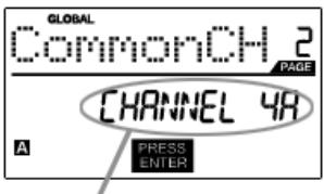
MIDI COMMON CHANNEL FIELD
You can assign the MIDI Common Channel to a specific MIDI Channel (i.e. A1). Any and all pads, buttons, knobs or faders assigned to the MIDI Common Channel (CC) will transmit MIDI information via the channel number that you select in this field.
- While in Global Mode, press [> button to scroll to MIDI Common Channel (page 2).
- Turn [VALUE] dial to select desired MIDI Channel.
- Press [ENTER] to set the MIDI Channel.
Note: If you change which channel the MIDI Common Channel is using, you need to set any device that is controlled by the Common Channel to receive on the same channel.
LCD CONTRAST - Page 3
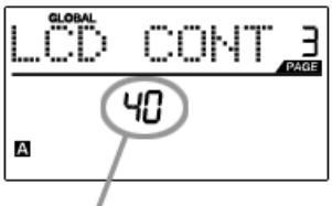
LCD CONTRAST
The contrast of the LCD can be adjusted for optimal viewing.
- While in Global Mode, press [> to scroll to LCD CONT (page 3).
- Turn [VALUE] dial to select a contrast level.
- Press [ENTER] to set contrast level.
PAD SENSITIVITY - Page 4
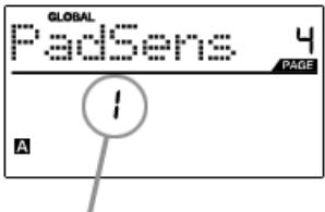
PAD SENSITIVITY FIELD
PAD SENSITIVITY allows you to adjust how sensitive the pads will be to the touch. Adjust this setting if you find it hard to achieve maximum velocity when you hit the pads hard, or if you are getting high velocities when you hit softly.
If the Pad Sensitivity number is set to low number, it's harder to get a high velocity value even if you hit a pad hard. If the Pad sensitivity number is set to a high number, it may become too easy to get high velocities even when you hit a pad softly.
- While in Global Mode, press [> to scroll to PadSens (page 4).
- Turn [VALUE] dial to change Pad Sensitivity.
- Press [ENTER] to set Pad Sensitivity.
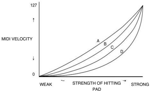
PAD VELOCITY CURVE - Page 5
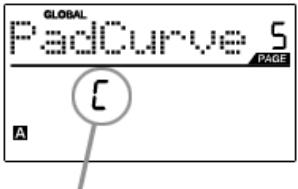
PAD VELOCITY CURVE FIELD
A PAD VELOCITY CURVE describes how the pads on the MPD32 are outputting MIDI velocities, based on a certain ratio of the input / output velocity that characterizes the particular curve. The Pad Velocity Curve feature is intended to help you optimize the pads on the MPD32 for your particular playing style and can add expressivity and control to your performance. If you find it difficult to achieve a comfortable velocity range for your playing style (you cannot get a velocity of 127 even if you hit the pad very hard, or vice versa, you get velocity 127 easily even if you hit the pad softly) you can adjust the velocity curve as desired.
- While in Global Mode, press [> to scroll to PadCurve (page 5).
- Turn [VALUE] dial to change the Pad Velocity Curve (the 4 curves are shown below).
- Press [ENTER] to set Pad Velocity Curve.
PAD THRESHOLD - Page 6
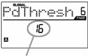
PAD THRESHOLD FIELD
PAD THRESHOLD is the minimum force required to activate the pads. If you experience "ghost" triggering due to stage vibrations, you may wish to set this threshold higher. On the other hand, if you find it difficult to trigger sounds when playing the pads lightly, you may wish to set this value to a lower number.
- While in Global Mode, press [>] to scroll to PdThresh (page 6).
- Turn [VALUE] dial to select value.
- Press [ENTER] to set Pad Threshold.
MIDI CLOCK - Page 7
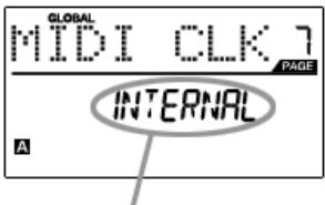
MIDI CLOCK FIELD
MIDI CLOCK is used to synchronize devices together. In addition, MIDI Clock on the MPD32 is used to synchronize the Note Repeat feature. The MPD32 can be a master or slave for MIDI Clock transmission and reception.
- While in Global Mode, press [>] to scroll to MIDI CLK (page 7).
- Turn [VALUE] dial to select "Internal" if you would like to generate MIDI Clock internally or "External" if you would like to slave the MPD32 to an external MIDI Clock source.
- Press [ENTER] to set MIDI Clock source.
Note: If "External" has been selected as a MIDI Clock source, the [TAP TEMPO] button will be disabled.
TAP TEMPO AVERAGE - Page 8
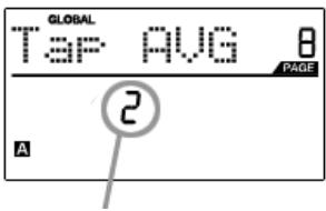
TAP AVERAGE FIELD
When using [TAP TEMPO] button to set the tempo, the MPD32 averages a number of taps in order to determine the tempo. You can set the number of taps used to determine the TAP TEMPO AVERAGE in this field.
- While in Global Mode, use [>] button to scroll to Tap AVG (page 8).
- Turn [VALUE] dial to select number of taps.
- Press [ENTER] to set tap average.
SAVE SETUP - Page 9
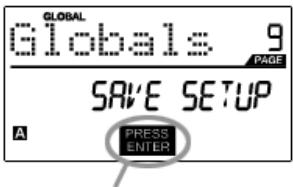
PRESS ENTER TO SAVE
SAVE SETUP allows you to save any changes you may have made to the global parameters.
- While in Global Mode, press [> to scroll to Globals (page 9). You will see "Save Setup" displayed on the screen.
- Press [ENTER] to save all the global settings on the MPD32.
SYSEX TX - Page 10
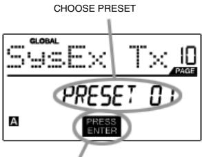
PRESS ENTER TO TRANFER
SYSEX TX allows you to transfer Preset data from the MPD32 via SysEx. This data includes Controller Numbers, MIDI Channels and various other parameters.
- While in Global Mode, press [> to scroll to SysEx Tx (page 10).
- Turn the [VALUE] dial to select which Preset's information you would like to transfer.
- Press [ENTER] to save all the global settings on the MPD32.
SysEx transfers to the MPD32
You can also load preset data into the MPD32 from an external source by "playing" a SysEx file into the MPD32. This can be done with a variety of SysEx applications, many of which are widely and freely available over the Internet.
- Make sure that the device is connected to the MPD32 either via the USB or the MIDI port.
- Make sure that you are in Preset Mode.
- "Play" the SysEx file on your external device or computer.
Please note that when transferring SysEx information into the MPD32, the data will override the data of the original Preset which was sent to your SysEx editor. For example, if you transfer Preset 5 to your SysEx editor and then send it back to the MPD32, the data will overwrite Preset 5.
VERSION - Page 11
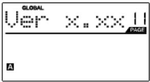
VERSION allows you to see what version of the operating system and firmware is currently loaded onto the MPD32.
While in Global Mode, press [>] to scroll to Ver (page 11) for version information.
PROGRAM CHANGE MODE
A Program Change, often referred to as a Patch Change, is a MIDI message used for sending data to devices to cause them to change to a new program. This allows you to tell a hardware or software device which sound to play. For example, if your MPD32 is controlling an acoustic drum patch on your DAW, using a Program Change command allows you to easily switch to a percussion patch.
There are two different types of Program Change messages on the MPD32:
PROG CHANGE - This event transmits a regular Program Change message (0-127), allowing you to switch among 128 different program banks.
PROG+BANK - This event transmits a Program Change message (0-127), along with a Bank L (Least Significant Bit) Change message (0-127) and a Bank M (Most Significant Bit) Change message (0-126), allowing access of up to 16384 different program banks. You can use PROG+BANK if your DAW or external device supports LSB and MSB.
To enter Program Change mode, press the [PROGRAM CHANGE] button. Then, turn the [VALUE] dial to select either a PROG CHANGE or PROG+BANK event.
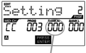
PROG CHANGE (Program Change)
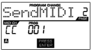
PROG CHANGE allows you to transmit a regular Program Change message.
- Select PROG CHANGE with the [VALUE] dial.
- Press [ENTER] to see the next page of parameters.
- Press the [<] button to access the MIDI CH field - this is the MIDI Channel which will be used to transmit the Program Change message. You can change the MIDI Channel by turning the [VALUE] dial. Then, press [>] to go to the next field.
- In the PROG field, choose the program number with the [VALUE] dial.
- Press [ENTER] to send the Program Change message.
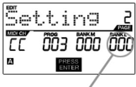
PROG+BANK (Program Change with Bank Change)
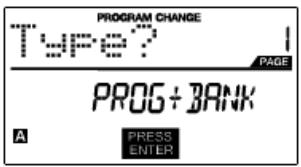
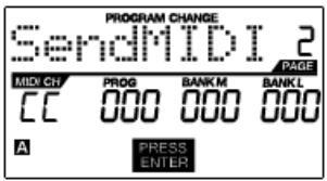
PROG+BANK allows you to send a Program Change with Bank Change message to your DAW or external sound module.
- Select PROG+BANK with the [VALUE] dial.
- Press [ENTER] to see the next page of parameters.
- Press the [<] button to access the MIDI CH field - this is the MIDI Channel which will be used to transmit the message. You can change the MIDI Channel by turning the [VALUE] dial. Then, press [>] to go to the next field.
- In the PROG field, choose the program number with the [VALUE] dial. Press [>] to go to the next field.
- In the BANK M field, select the MSB (Most Significant Bit) of information. Press [> to go to the next field.
- In the BANK L field, select the LSB (Least Significant Bit) of information.
- Press [ENTER] to send the Bank and Program event.
RESETTING FACTORY DEFAULTS

If you ever would like to restore all the presets to the factory default, do the following:
- Press [> - this will open the SAVE screen.
- Press [> again - This will open the PRESET NAME screen.
- Press [> to move past each letter in the current program's name until the last character is reached.
- Press [>] one more time - The FACTORY will be displayed.
- Press [ENTER] to restore factory defaults.
\*\*WARNING\*\*
Pressing [ENTER] will erase ALL presets and reload the Factory Presets that shipped with the unit!!
Frequently ASKED QUESTIONS
Question: Does the Note Repeat feature on the MPD32 work similarly to Note Repeat on the Akai MPC series?
Answer: Yes, the MPD32 features the same Note Repeat algorithm as can be found on the legendary Akai MPC series. This feature allows you to perform and program rhythm patterns that would otherwise be nearly impossible to do by hand.
Question: Does the MPD32 have internal sounds?
Answer: No. The MPD32 is a MIDI-controller, which means that it does not contain any sounds inside but is instead used to control external sound devices, such as hardware and software synthesizers, sequencers and drum machines.
Question: Can the MPD32 be syncsed to external devices?
Answer: Yes, the MPD32 can receive MIDI Clock through the USB and MIDI IN connection. This means that you can synchronize tempo-based features, such as Note Repeat, to an external source. To synchronize the MPD32 to an external MIDI Clock source, enter Global Mode, scroll to MIDI Clock and select "External".
Question: Do I need to use a power adapter if I am using the MPD32 with a computer?
Answer: No. The MPD32 will draw power directly from the USB port. However, if your USB port does not supply enough power or if you are using a USB hub, it may be necessary to use a power adapter.
Question: What software applications is the MPD32 compatible with?
Answer: The MPD32 is compatible with any software or hardware device which supports the MIDI protocol. Please consult your specific hardware or software device's documentation for instructions on enabling the MPD32 as a MIDI input device.
Question: Can I use the MPD32 as a MIDI interface for other MIDI devices?
Answer: Yes. The MPD32 functions as a MIDI interface which can send and receive from other MIDI devices connected to it.
Question: Can I control multiple devices with the MPD32?
Answer: Yes. The MPD32 can transmit information on 16 MIDI channels on 2 ports for a total of 32 different MIDI Channels.
Question: How many different Presets can the MPD32 hold?
Answer: The MPD32 can store up to 30 Presets of controller configurations and settings for use with various software and hardware modules. Presets can easily be copied, edited and stored for quick recall of desired configurations.
Question: Can I send Program Change messages to my software or hardware devices?
Answer: Yes. You can send program change messages in Program Change mode. In addition, pads and buttons may also be assigned to transmit program change messages.
Question: Are the pads on the MPD32 velocity and pressure sensitive?
Answer: Yes. The MPD32 sports real MPC velocity and pressure sensitive pads. This allows you to be extremely expressive with your programming and performance.
Question: What type of pads is used on the MPD32?
Answer: The MPD32 features the same pads as the MPC2500.
Question: Are the knobs on the MPD32 endless?
Answer: The knobs on the MPD32 are endless pots. This allows you to limit the range of the knobs, as well as use them as increment/decrement controls. Please note that your software application must be able to receive and recognize NRPNs for Increment/decrement functions to work.
Question: I see 8 knobs, 8 faders, 8 buttons, and 16 pads. Is that all I get?
Answer: No. The MPD32 features multiple banks of controllers and pads, which can be accessed with the [PAD BANK] and [CONTROL BANK] buttons. This allows you to access significantly more parameters than the amount of physical controllers. There are 3 control banks, which effectively give you 72 (3x24) controllers. There are also 4 different pad banks which give you a total of 64 (4x16) pads.
TROUBLESHOOTING
| PROBLEM | CAUSE | SOLUTION |
| The display does not light up. | No power. | Please make sure that the MPD32 is connected to your computer and that the computer is powered on. |
| If using a power adapter, please make sure that the adapter is plugged into a live power outlet. |
| No sound from target device. | MPD32 not properly connected. | Check your computer's USB connection to confirm that the MPD32 is recognized. If necessary, replug the connection and restart your computer. |
| If controlling an external hardware module, make sure that the MPD32's MIDI OUT is connected to the device's MIDI IN port. |
| MPD32 connected after software application has started. | Restart the software application with the controller plugged in. |
| Problem is caused by use of a USB hub. | Unplug the MPD32 from the USB hub and connect directly to your computer. |
| Software application not set to receive MIDI data from the MPD32. | Ensure that the MPD32 or "USB" MIDI device is listed as an active MIDI source in your application. Usually, the MIDI settings can be accessed through the application's Preferences menu. |
| MPD32's MIDI channel not the same as application's incoming MIDI channel. | Make sure that the MPD32 is sending MIDI information on the channel that the target device expects. |
| Notes sustain continuously. | Footswitch was plugged in after the MPD32 was powered on. | Turn the unit's power off, wait a moment and then turn it on again. |
| Stuck notes due to incomplete MIDI data. | Turn the unit's power off, wait a moment and then turn it on again. |
| Footswitch works in reverse. | Footswitch was plugged in after power was turned on. | With the footswitch plugged in, turn the unit's power off, wait a moment, and turn it on again. |
| Note Repeat is not synchronized to my clock source. | Clock source on MPD32 set to "Internal". | In Global Mode, change the MIDI Clock setting to "External". Also, make sure that your software is set to send MIDI Clock to the MPD32. |
| My Seq/DAW is set to send clock but Note Repeat is not working. | Software DAW is not in play mode. | If your software DAW is not playing, it will not be sending clock. |
| My fader or knob works in reverse. | Controller minimum value is set higher than its maximum. | Edit the controller and set the minimum value to be lower than the maximum. |
| Transport control does not work. | Software does not support MMC messages, MIDI START/STOP or the MIDI CC mode. | Edit the transport control to send MIDI messages instead. Make sure that the Transport mode on the MPD32 matches the receive mode of your software. |
| I am only hearing one sound when I hit different pads | 16 Level function is engaged. | When engaged, the 16 Level function will map the last hit pad to all 16 pads. Deactivate 16 Level to return to normal operation. |
| The pads always play at maximum velocity (127). | Full Level feature is engaged. | When engaged, the Full Level function will cause all the pads to output maximum velocity, no matter how hard they are hit. Turn off Full Level to return to normal operation. |
TECHNICAL SPECIFICATIONS
| GENERAL |
| Display | custom LCD w/ backlight |
| Dimensions (WxDxH) | 730mm x 300mm x 100mm |
| Weight | 5.8kg |
| Power | ~100mA, 5V DC via USB
~1A, 6V DC via external adaptor |
| Number of Presets | 30 |
| MIDI output channels over USB | 48 (16 channels x 3 ports) |
| MIDI output channels from 5-pin MIDI | 16 |
| Drum pads | 16 (velocity and pressure sensitive) |
| Drum pad banks | 4 |
| Faders | 8 |
| 360 degree knobs | 8 |
| Switches | 8 |
| Accessories | User's manual
USB cable (1m)
CD-ROM disc |
| INPUTS/OUTPUTS |
| MIDI inputs | 5-pin DIN x 1 |
| MIDI outputs | 5-pin DIN x 1 |
| USB | Slave connector x 1 (MIDI over USB) |
| DC IN | 6V DC, 1A |
Please visit the Akai Professional website (www.akaipro.com) regularly for additional information, news and firmware upgrades for the MPD32.
For additional technical support:
EMAIL: support@akaipro.com
TEL: 401.658.4032 (U.S)
MANUAL REVISION 1.01