
MPD24 - MIDI Controller AKAI - Free user manual and instructions
Find the device manual for free MPD24 AKAI in PDF.
| Product Type | MIDI Controller |
| Brand | AKAI |
| Model | MPD24 |
| Dimensions (W x D x H) | 318 x 283 x 50 mm (68 mm max) |
| Weight | 2.18 kg |
| Power | USB: ~200 mA, 5 V DC; External adapter: ~500 mA, 6 V DC |
| Display | Backlit LCD display |
| Pads | 16 MPC-style velocity and pressure-sensitive pads, 4 banks (64 pads total) |
| Rotary knobs | 8 high-resolution 360° knobs |
| Potentiometers | 6 assignable potentiometers |
| Transport buttons | 5 buttons with MMC (MIDI Machine Control) control |
| Connectivity | USB (MIDI over USB), MIDI IN (5-pin), MIDI OUT (5-pin), DC power input |
| Number of presets | 30 |
| MIDI channels (via USB) | 48 (16 channels x 3 ports) |
| MIDI channels (via DIN) | 16 |
| Compatibility | PC (Windows XP and later), Mac (OS X and later) – no driver installation required |
| Included accessories | User's guide, USB cable (1 m), CD-ROM (Uniquest Editor), DVD-ROM (BFD Lite) |
| Main functions | Drum pad control, assignable buttons and potentiometers, Preset/Edit/Global/Program Change modes, MIDI Note, Control Change, Aftertouch, MMC transmission |
| Maintenance and cleaning | Clean with a dry, soft cloth. Do not use liquids or abrasive products. |
| Safety | Do not expose to moisture, shocks, or extreme temperatures. Disconnect before any cleaning. |
| Spare parts and repairability | Contact AKAI after-sales service for any spare parts or repairs. |
| General information | Manufacturer: AKAI Professional. The MPD24 is based on the MPC series concept, designed for rhythm production and intuitive MIDI control. |
Frequently Asked Questions - MPD24 AKAI
User questions about MPD24 AKAI
0 question about this device. Answer the ones you know or ask your own.
Ask a new question about this device
Download the instructions for your MIDI Controller in PDF format for free! Find your manual MPD24 - AKAI and take your electronic device back in hand. On this page are published all the documents necessary for the use of your device. MPD24 by AKAI.
USER MANUAL MPD24 AKAI
Congratulations on your purchase of the Akai Professional MPD24 USB/MIDI Control Unit! Based on the concept of the original MPC series, the MPD24 is the ultimate tool for rhythm production. It combines the flexibility of a MIDI controller with the intuitive feel of a drum pad.
For many years, studio musicians and performers have been faced with the dilemma of how to best trigger and program drum material. At Akai Professional we strongly believe that using a MIDI controller keyboard interface to do so simply doesn't cut it! This is our motivation for developing the MPD24. A truly fresh and intuitive controller, the MPD24 will animate and breathe life into your production style and your performance. We sincerely hope that you enjoy this product, as much as we enjoyed building it for you!
KEY FEATURES
Mac/PC compatible - class-compliant so no driver installation is necessary
MIDI or USB connectivity
16 velocity and pressure sensitive, MPC-style pads for ultimate feel and control
4 switchable pad banks for a total of 64 pads
8 high-resolution 360-degree assignable knobs
6 assignable sliders
5 dedicated transport control keys with MIDI Machine Control functionality
bright, easy-to-navigate LCD display
- programmable, recognizable, scalable, customizable, scalable, scalable, scalable, scalable, scalable, scalable, scalable, scalable, scalable, scalable, scalable, scalable, scalable, scalable, scalable, scalable, scalable, scalable, scalable, scalable, scalable, scalable, scalable, scalable, scalable, scalable, scalable, scalable, scalable, scalable, scalable, scalable, scalable, scalable, scalable, scalable, scalable, scalable, scalable, scalable, scalable, scalable, scalable, scalable, scalable, scalable, scalable, scalable, scalable, scalable, scalability, scalable, scalable, scalable, scalable, scalable, scalable, scalable, scalable, scalable, scalable, scalable, scalable, scalable, scalable, scalable, scalable, scalable, scalable, scalable, scalable, scalable, scalable, scalable, scalable, scalable, scalable, scalable, scalable, scalable, scalable, scalable, scalable, scalable, scalable, scalable, scalable, scalable, scalable, scalable, scalable, scalable, scalable, scalable, scalable, scalable, scalable, scalable, scalable, scalable, scaling
- programmatical
- programmable
- programmable
- programmable
- programmable
- programmable
- programmable
- programmable
- programmable
- programmable
- programmable
- programmable
- programmable
- programmable
- programmable
- programmable
- programmable
- programmable
- programmable
- programmable
- programmable
- programmable
- programmable
- programmable
- programmable
- programmable
- programmab
- programmab
- programmab
- programmab
- programmab
- programmab
- programmab
- programmab
- programmab
- programmab
- programmab
- programmab
- programmab
- programmab
- programmab
- programmab
- programmab
- programmab
- programmab
- programmab
- programmab
- programmab
- programmab
- programmab
- programmab
- programmac
- programmac
- programmac
- programmac
- programmac
- programmac
- programmac
- programmac
- programmac
- programmac
- programmac
- programmac
- programmac
- programmac
- programmac
- programmac
- programmac
- programmac
- programmac
- programmac
- programmac
- programmac
- programmac
- programmac
- programmac
- programmab
- programmab
- programmab
- programmab
- programmab
- programmab
- programmab
- programmab
- programmab
- programmab
- programmab
- programmab
- programmab
COMPUTER REQUIREMENTS
PC running Windows XP
Macintosh running OS10.x
One available USB port
TOP PANEL OVERVIEW
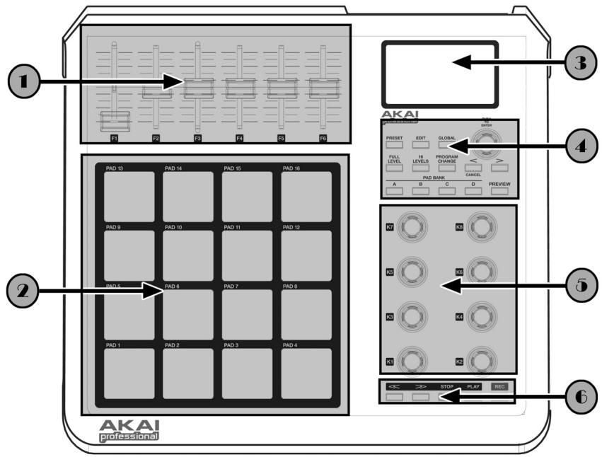

6 ASSIGNABLE CONTINUOUS CONTROLLER SLIDERS
Each slider can be used to send continuous controller data to a Desktop Audio Workstation or external MIDI device.

16 MPC-STYLE PRESSURE AND VELOCITY SENSITIVE PADS
Each pad can be used to trigger drum hits or samples by tapping on them. The pads are pressure and velocity sensitive, which makes them very responsive and intuitive to play.

NAVIGATION / MENU DISPLAY SECTION
This is the LCD display used for navigating menus, displaying data, and affecting change on the MPD24's options and parameters.

NAVIGATION/CONTROL BUTTONS
These are the main buttons used for navigation, program change, pad bank change, previewing, and switching amongst the different modes of operation.

8 ASSIGNABLE CONTINUOUS CONTROLLER KNOBS
Like the sliders, each 360-degree knob can be used to send continuous controller data to a Desktop Audio Workstation or external MIDI device.

TRANSPORT CONTROL BUTTONS
These dedicated buttons can be used to send transport information to remotely control a hard disk recording system or any other machine that understands MIDI Machine Control (MMC).
REAR PANEL OVERVIEW
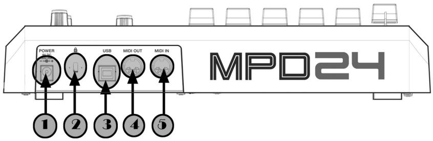

DC POWER INPUT
Plug in a DC adapter if you do not want to power the MPD24 through the USB connection.

KENSINGTON LOCK
Use this lock to attach and secure the MPD24 to a table or surface.

USB CONNECTOR
Plug a standard USB cable into this outlet and into the USB port of your computer. The computer's USB port will provide power to the MPD24.

MIDI OUT CONNECTOR
Use a five-pin MIDI cable to connect the MIDI OUT of the MPD24 to the MIDI IN of an external device.

MIDI IN CONNECTOR
Use a five-pin MIDI cable to connect the MIDI OUT of an external MIDI controller to the MIDI IN of the MPD24.
HOOKUP DIAGRAM
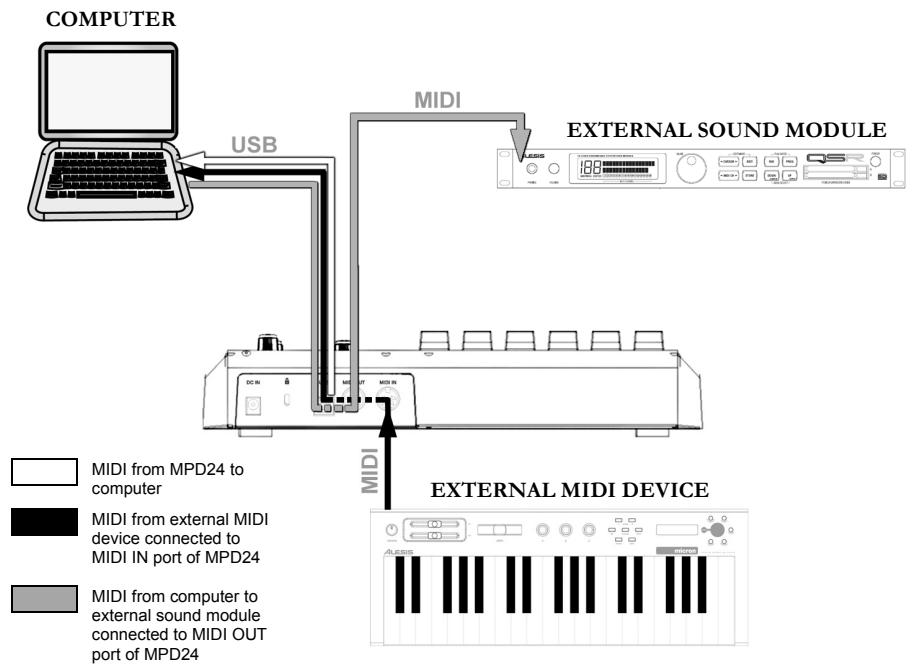
SCENARIO 1
- Connect a USB cable from your computer to the MPD24.
- If you would like to use an external sound module, connect a 5-pin MIDI cable from the MIDI OUT of the MPD24 to the MIDI IN of the external device.
- If you would like to use another MIDI controller in your setup, connect a 5-pin MIDI cable from the MIDI OUT of the external MIDI device to the MIDI IN of the MPD24.
A NOTE ABOUT USING THE MPD24 WITH SOFTWARE:
- Make sure that the MPD24 and all external devices are connected and that the USB cable is connected to your computer before opening any software applications on your computer with which you might want to use the MPD24. If the unit is not plugged in before, your software application might not recognize the MPD24 as an available device.
- In your software application, you will need to set the MPD24 as a default MIDI input device. This is usually done in the MIDI section of the Preferences menu.
IMPORTANT:
The operation of the MIDI OUT port changes depending on whether or not a USB cable is connected to the MPD24.
USB cable connected:
MIDI data from your computer is passed to the MIDI OUT port. When a USB cable is connected, you should activate "MIDI echo" in your sequencer if you want the MPD24 to control another external device.
USB cable not connected:
Whatever you play on the MPD24 is sent to the MIDI OUT port.
Note: If you have another device connected to the MPD24's MIDI IN port, that device's MIDI information will be ignored.
SCENARIO 2

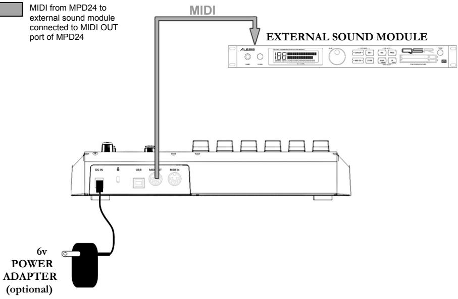
MIDI from MPD24 to external sound module connected to MIDI OUT port of MPD24
- Plug a 6v power adapter into a power outlet and connect it to the MPD24.
- Connect a 5-pin MIDI cable from the MPD24's MIDI OUT to the MIDI IN of an external sound module.
NAVIGATION AND CONTROL BUTTONS EXPLAINED
PRESET
This button calls up PRESET MODE. You can select and recall different preset programs in this mode.
EDIT
This button calls up EDIT MODE, which allows you to edit the behavior of the pads, knobs and sliders for each preset.
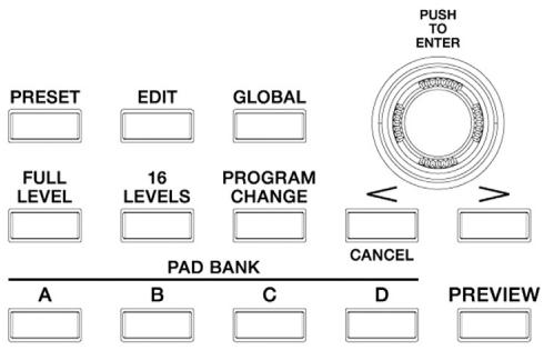
GLOBAL
This button calls up GLOBAL MODE, where MIDI reset commands and global system parameters and preferences are set.
VALUE (Push To Enter)
This dial is used to increment and decrement preset numbers, parameter values and settings.
IMPORTANT TIP!
The [VALUE] dial also functions as an [ENTER] button. This is done by pressing down on the dial.
[ \left[ < \right] \text{and} \left[ > \right] \text{BUTTONS} ]
These buttons are used to navigate through the fields of the display menus.
IMPORTANT TIP!
The [<] button also functions as a [CANCEL] button.
PAD BANK
These 4 buttons switch between pad banks A, B, C, D. You can store different sounds in each one of the 4 different banks, giving you access of up to 64 different sounds you can trigger.
PREVIEW
This button allows you to see what value will be sent by a knob or slider before transmitting the value. If you hold down the [PREVIEW] button, you can move a knob or slider to a desired value and that value will be sent once the [PREVIEW] button is released.
FULL LEVEL
When the [FULL LEVEL] button is activated, the MPD24 pads always play back at maximum velocity (127). This way, no matter how hard or soft you hit a pad, the MPD24 will always trigger the sound at its maximum velocity (volume).
16 LEVELS
When you press [16 LEVELS], you can use the 16 pads to change a selected pad's velocity in 16 steps. This allows you to have more control over the velocity of the desired sound. When this button is pressed the last pad that was hit gets mapped to all 16 pads. The pads output the same note number and pressure controller as the initial pad, but the velocity is fixed at the values in the diagram below, regardless of how hard you hit each pad.
PADS AND CORRESPONDING VELOCITIES
| 103 | 111 | 119 | 127 |
| 71 | 79 | 87 | 95 |
| 39 | 47 | 55 | 63 |
| 7 | 15 | 23 | 31 |
TRY IT!
Try mapping a sound such as a snare drum to one of the pads and then see how expressive the 16 Levels option allows you to be with your playing.
PROGRAM CHANGE
Pressing this button allows a program change or program with bank change message to be transmitted. This allows you to tell a hardware or software module which the MPD24 is controlling, what sound banks to use.
REW,FF,STOP,PLAY,RECORD
These five buttons are dedicated buttons for sending MIDI Machine Control commands.
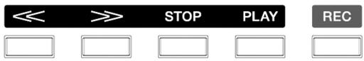
MIDI MACHINE CONTROL (MMC)
... is a protocol specifically designed to remotely control hard disk recording systems or other machines over a MIDI cable.
DISPLAYING INFORMATION
As you are working with the MPD24, the LCD screen will help you keep track of what values and parameters are entered and sent to external devices. There are several kinds of information that the MPD24 will display while in use: NOTE, AFTERTOUCH (Channel Pressure), CONTROL CHANGE, MIDI MACHINE CONTROL (MMC), and Preview Mode information.
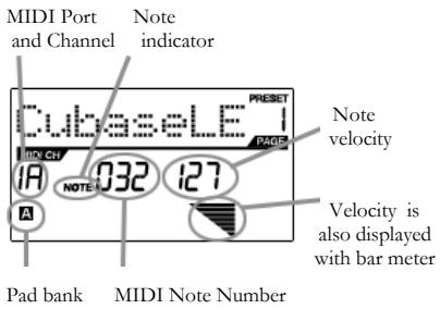
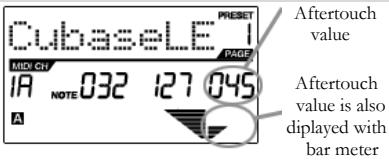
NOTE
When a PAD is hit, the MPD24 will output MIDI Note On messages to trigger sounds on your DAW or external device. Each pad can have its own MIDI Note Number associated with it. When you hit a pad, the screen will display the MIDI Note Number, the MIDI Port and Channel that the pad is using, the pad bank, and the velocity (how hard you hit the pad).
Please see 'Editing Pads'(page 14) for more information on MIDI Notes and Pads.
NOTE AFTERTOUCH (Channel Pressure)
When enabled, AFTERTOUCH is MIDI data sent when pressure is applied to one of the pads after it has been struck and while it is being held down. It will be displayed on the far right of the display as you apply pressure to the pad.
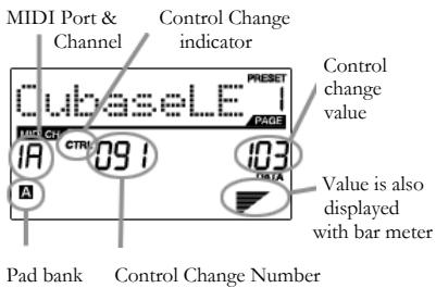
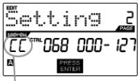
CONTROL CHANGE
When a KNOB or SLIDER is used, the MPD24 will output MIDI Control Change data. This data is used to change certain parameters on your DAW or external sound module. When you move a knob or slider, the screen will indicate the Control Change (CC) Number, value, and MIDI Channel.
Please see 'Editing Knobs and Sliders' (page18) for more information on Control Change.
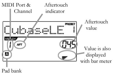
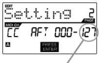
CONTROL AFTERTOUCH
The knobs and sliders on the MPD24 can also be set to transmit AFTERTOUCH information.
Please see 'Editing Knobs and Sliders' (page 20) for more information on setting knobs and sliders to transmit Aftertouch.
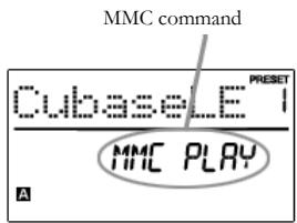
MIDI MACHINE CONTROL COMMAND (MMC)
MIDI MACHINE CONTROL (MMC) is
commonly used to send transport control messages to hardware record or playback machines. MMC allows you to centralize control of your studio from the MPD24. For example: Pressing [PLAY] on the MPD24 sends an MMCPLAY message to a connected multi-track recorder, which begins playing. When [STOP] is pressed on the MPD24, the deck also stops.
PREVIEWING
When the [PREVIEW] button is held down, and a slider or knob is moved, the LCD displays the screen on the right. The display shows the assigned event and value of moved knob or slider. The last value of the controller is also displayed. You can set a new value by using one of the knobs or sliders. This value will be sent when you release the [PREVIEW] button.
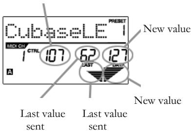
Control Change Number
THE ADVANTAGES OF PREVIEWING
[PREVIEW] button allows you to see what value will be sent by a controller, without actually sending the value. This gives you precise control over your parameters. For example, you might be using one of the knobs to control the cut-off frequency of a high-pass filter. You would like to filter out a precise frequency range but trying to do this by hand might not give you the precise results that you are looking for. Try holding down the [PREVIEW] button, setting the position of the slider to where you would like the cut-off frequency to be and then releasing the [PREVIEW] button. You will see that the MPD24 will immediately jump to that position.
MODES
The MPD24 has four different modes of operation. Each mode can be accessed by pressing the corresponding button on the MPD24. Following is a short description of each mode:
Preset Mode -
This mode allows you to load, save and copy Presets. A Preset is a collection of information about how different sliders, knobs, and pads will behave. Using Presets allows you to save different configurations so you can quickly load them when you need them, without having to reprogram the MPD24 every time. (page 11)
Edit Mode -
This mode allows you to edit the configuration of the MPD24. EDIT MODE is a powerful tool for customizing your set-up. In this mode, you can make changes to how the pads, knobs and sliders are behaving. For example, you may wish to have a slider or a knob transmit only a limited range of MIDI data, or you may wish to have a pad that transmits on a different MIDI Channel. You can change these and other various parameters of the pads, knobs and sliders in EDIT MODE. (page 13)
Global Mode -
This mode allows you to set global parameters and make general changes to how your MPD24 is functioning. For example, in GLOBAL MODE you can change how the pads respond to the touch, or change the brightness of the LCD screen. The parameters that you can modify in GLOBAL MODE also include controller resets, pad response curves, display brightness, and more. (page 21)
Program Change Mode – This mode allows you to transmit various Program Change messages. In this mode, you can tell your DAW or an external device to switch to a different program bank of sounds. This way, you can avoid having to manually switch between different programs on your DAW or external device. (page 26)
PRESET MODE
What is a Preset?
A Preset is a collection of information about how different sliders, knobs, and pads will behave. Using Presets allows you to save different configurations so you can quickly load them when you need them, without having to reprogram the MPD24 every time.
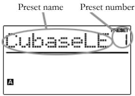
The MPD24 features different Preset banks that you can load and write to. When you turn on the MPD24, it will automatically go into PRESET MODE and Preset 1 will be displayed on the screen. You can also press the [PRESET] button to call up this mode. In PRESET MODE you can load, save/copy and rename Presets. You can navigate between these three pages with the [< ] and [>] buttons.
Page 1 - Load Preset
- While you are in PRESET MODE, you can change Presets with the [VALUE] dial below the screen. Turning the dial increments or decrements the current Preset number and displays the screen on the right:
When you do this, you will notice that 'PRESS ENTER' will begin to blink.
- Pressing [ENTER] loads the selected Preset. Pressing [<] button or [PRESET] button cancels and returns you to the Preset that was last selected.

Page 2 - Save/Copy Preset
In PRESET MODE, you can also save and copy a Preset to a new location. This allows you to save any changes that you would have made to the Preset in EDIT MODE.
Note that if you are saving the Preset to the same location (same preset number) the screen will say 'SAVE TO' and if you are saving to a different location (different preset number), the screen will display 'COPY TO'.

Destination
- While you are in PRESET MODE, press [> button until you see the 'SAVE TO' screen similar to the one shown above.
- You can select the location where you want to save the Preset by turning the [VALUE] knob. When you do this, you will notice that the 'PRESS ENTER' segment will begin to blink.
- Press [ENTER] to save current Preset to the destination. Pressing [<] button or [PRESET] button cancels the operation and returns you to the preset play mode.
Page 3 - Name Preset
While you are in PRESET MODE, you can also change the Preset name. This way you can assign specific names to different Presets so you can better keep track and quickly access different controller configurations.
- To name or rename the Preset, press the [> button until you see 'Preset Name' displayed on the screen.
You will notice that the first letter of the name will begin blinking.
- Turn the [VALUE] dial to change the blinking character.
- To move between the characters, use [<] and [>] buttons.
- When done, press [PRESET] again. The name will be saved.
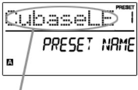
Enter Preset Name in this field
EDIT MODE
Pressing the [EDIT] button calls up EDIT MODE. In EDIT MODE, you can change the parameters of the pads, knobs and sliders. The EDIT MODE allows you to fully customize and optimize your controller for the best desired performance.
The different parameters that you can edit are organized under three different pages on the display and are described below. Depending on which event type you select on Page 1, you will be given different parameters which you can edit on Page 2:
| PAGE 1(event type) | PAGE 2(parameters) | |
| PADS | NOTE | MIDI CHANNELNOTE NUMBERON/OFF BEHAVIORPRESSURE BEHAVIOR |
| PROGRAMCHANGE | MIDI CHANNELPROGRAM CHANGE NUMBERBANK M (MSB)BANK L (LSB) | |
| KNOBSandSLIDERS | CONTROLCHANGE | MIDI CHANNELRANGE - MINIMUM VALUERANGE - MAXIMUM VALUE |
| AFTERTOUCH | MIDI CHANNELRANGE - MINIMUM VALUERANGE - MAXIMUM VALUE |
HOW TO NAVIGATE THE EDIT MODE:
- Press the [EDIT] button.
- To select the controller you wish to edit, just move any slider, knob or hit a pad - This will prompt the screen to display the properties of that particular controller.
- You can move through desired fields or pages with [<] and [>] buttons.
- Pressing [ENTER] will take you to the next page.
REMEMBER!
The [VALUE] dial functions as an
[ENTER] button when you press it down.
The [<] button also functions as a
[CANCEL] button.
Editing Pads
The pads on the MPD24 can either be set to transmit Note or Program Change information when they are hit. The default operation of the pads is set to Note, which means that when a pad is hit it will generate Note On/Off messages to trigger sounds. The pads may also be set up to transmit Program Change information, which allows you to switch to different programs (instruments or sound banks) on your DAW or external device by hitting the pads. If you would like to know more about Program Change, please read 'Program Change Mode' on page 25.
What is a Note Message?
A Note Message is a MIDI message that tells an instrument to play a note. More generally, this means that Note Messages are used to start and stop sounds. When you press one of the pads, a 'Note On' message is sent to your DAW or external device. This toggles a note or sample. When you release the pad, a 'Note Off' message is sent. This message will stop the note or sample.
What is a Program Change?
A Program Change Message allows you to tell your DAW or external device to switch to a new program. Most often, these programs are collections of samples or instruments. You can use Program Change to tell your DAW or external device to switch to a new instrument or bank of sounds.
For more information, see 'Program Change Mode' on page 25.
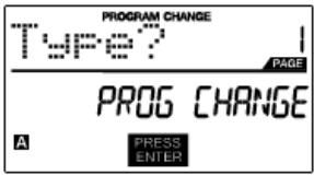
SELECTING PAD EVENT TYPE:
- Press [EDIT] button to enter EDIT MODE.
- Press the pad that you would like to edit.
- On Page 1, turn the [VALUE] dial to select 'NOTE' or 'PROG CHANGE' (Program Change) as the event type.
- Press [ENTER] to view Page 2.
Depending on which event type you select on Page 1, parameter options on Page 2 will be changed.
- Use [< ] and [>] buttons to move through fields on the second page.
The parameter fields available for each event type are outlined in the following pages.
A Note on MIDI Common Channel (CC)
The MIDI Common Channel (CC) is a grouping channel that pads, knobs, and sliders can be assigned to. The Common Channel allows you to group pads, knobs and sliders to transmit on the MIDI Port and Channel that is set for the MIDI Common Channel in GLOBAL MODE.
For example:
Your pads, knobs and sliders are assigned to the MIDI Common Channel. In GLOBAL MODE, you have assigned this channel to transmit on MIDI Channel #4 - so all the pads, knobs and sliders assigned to the MIDI Common Channel will transmit information on MIDI Channel #4. You might, at some point, want to switch all your pads, knobs and sliders to transmit on MIDI Channel #7. Instead of having to change the MIDI Channel for each pad, knob or slider, you could simply change the Common Channel to #7 in GLOBAL MODE. This will cause any pad, knob or slider that is assigned to the Common Channel (CC) to transmit on MIDI Channel #7.
For more information on setting MIDI Common Channel port and number, see 'Global Mode' on page 21.
NOTE - PARAMETERS
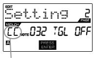
MIDI Port/Channel field
MIDI Channel field
This field sets the MIDI Port and Channel which the pad will use to transmit messages. You can assign pads to one of two MIDI Ports, A or B, and to one of 16 MIDI Channels on each port (i.e. B11). You may also assign the pad to the MIDI Common Channel.
- Use [<] button to select MIDI Port/Channel field.
- While in MIDI Port/Channel field, use [VALUE] dial to select desired MIDI Port and Channel.
- Use the [>] button to select the next field.
Note: When not used via USB, only pads assigned to port A will transmit MIDI information via the 5-pin MIDI port on the back of the MPD24.
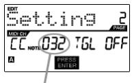
Note field
Note field
This field sets the MIDI Note Number that the pad will transmit when it is hit.
- Use [< ] or [>] button to select Note field.
- While in Note field, turn [VALUE] dial to select desired Note Number.
- Use the [>] button to select the next field.
Note: Software modules or drum machines are often programmed to trigger sounds based on specific Note Numbers associated with each sample. You may have to experiment setting different Note Numbers on the MPD24 to find the range that is suited for your application.
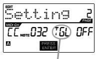
Play mode field
Play Mode field
Here, you can select whether the pad transmits Note On/Off information in a standard momentary (MTY) way like a keyboard, where hitting the pad generates a Note On and releasing it a Note Off message, or in a toggle (TGL) way where the first hit of the pad outputs a Note On, the second hit transmits a Note Off.
- Use [< ] or [>] button to select Play Mode field.
- While in Play Mode field, use [VALUE] dial to select desired Play Mode.
- Use the [>] button to select the next field.
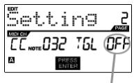
Pressure field
Pressure field
You can set the pad to transmit pressure information as a channel pressure message (CPR) or polyphonic pressure message (PPR).
- Use [< ] or [>] button to select Pressure field.
- While in Pressure field, use [VALUE] dial to select 'OFF', 'CPR', or 'MTY'.
PROGRAM CHANGE - PARAMETERS
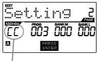
MIDI Port/Channel field
MIDI Channel field
Program Change messages can be sent on one of two MIDI Ports, A or B, and one of 16 MIDI Channels on each port (i.e. A7). You may also assign Program Change to use the MIDI Common Channel.
- Use [<] or [>] button to select MIDI Port/Channel field.
- While in MIDI Port/Channel field, use [VALUE] dial to select desired MIDI Port and Channel.
- Use the [>] button to select the next field.
Program Change field
Program Change field
In this field you can set which Program Change Number the pad will transmit when it is pressed.
- Use [< ] or [>] button to select Program Change field.
- While in Program Change field, use [VALUE] dial to select desired Program Change Number.
- Use the [> button to select the next field.
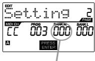
Bank M
Bank M
Bank M describes the Most Significant Bit (MSB) of information.
- Use [<] or [>] button to select Bank M field.
- While in Bank M field, use [VALUE] dial to select desired value.
- Use the [>] button to select the next field.
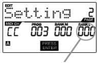
Bank L
Bank L
Bank L describes the Least Significant Bit (LSB) of information.
- Use [< ] or [>] button to select Bank L' field.
- While in Bank L field, use [VALUE] dial to select desired value.
Note:
You can also configure pads to send Program Change messages only, without specifying Bank M and Bank L. While editing Bank M and Bank L fields of a pad, use [VALUE] dial to set Bank M and Bank L to 'OFF' (beyond 000). This will cause the pad to transmit only a Program Change message.
Editing Knobs and Sliders
The knobs and sliders on the MPD24 are controllers which can be set to transmit Control Change or Aftertouch information. The default operation of knobs and sliders is to transmit Control Change information when used.
What is Control Change?
Control Change refers to the use of MIDI Continuous Controller data. Continuous Controller (CC) data are MIDI messages capable of transmitting a range of values, usually 0-127. CC's are commonly used for controlling volume, pan, mod wheel (#1) and other variable parameters on your DAW or sound module.
What is Aftertouch?
Aftertouch refers to MIDI data sent when pressure is applied to a pad after it has been struck, and while it is being held down or sustained. Aftertouch is often routed to control vibrato, volume, and other parameters. On the MPD24, the knobs and sliders can also be assigned to transmit Aftertouch information.
SELECTING KNOB OR SLIDER EVENT TYPE:
- Press [EDIT] button to enter EDIT MODE.
- Move the slider or turn the knob that you would like to edit.
- On Page 1, turn the [VALUE] dial to select 'CTRL CHANGE' (Control Change) or 'AFTERTOUCH' as the event type.
- Press [ENTER] to view Page 2.
Depending on which event type you select on Page 1, parameter options on Page 2 will be changed.
- Use [< ] and [>] buttons to move through field on the second page.
The parameter fields available for each event type are outlined in following pages of this manual.
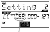
CONTROL CHANGE - PARAMETERS
MIDI Port and Channel field
MIDI Channel field
This field sets the MIDI Port and Channel which the knob or slider will use to transmit messages. You can assign knobs and sliders to one of two MIDI Ports, A or B, and to one of 16 MIDI Channels on each port (i.e. A14). You can also assign a knob or slider to use the MIDI Common Channel.
- Use < button to select MIDI Port/Channel field.
- While in MIDI Port/Channel field, use [VALUE] dial to select desired MIDI Port and Channel.
- Use the [>] button to select the next field.
Note: When not used via USB, only knobs and sliders assigned to port A will be transmitted via the 5-pin MIDI port on the back of the MPD24.
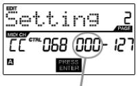
Control Change field
Control Change field
This field sets the Control Change Number that the knob or slider will transmit when it is used.
- Use [<] or [>] button to select Control Change field.
- While in Control Change field, use [VALUE] dial to select desired Controller Number.
- Use the [> button to select the next field.
Note: To be able to control a parameter in your DAW or sound module with a knob or slider, both the parameter and the knob need to be set to the same Controller Number.
Minimum Range field
Minimum Range field
This field is used to specify the minimum value that the knob or slider can output.
- Use [< ] or [>] button to select Minimum Range field.
- While in Minimum Range field, use [VALUE] dial to select desired minimum value.
- Use the [>] button to select the next field.
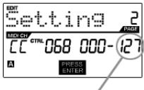
Maximum range field
Maximum Range field
This field is used to specify the maximum value that the knob or button can output.
- Use [<] or [>] button to select Maximum Range field.
- While in Maximum Range field, use [VALUE] dial to select desired maximum value.
For some applications, you might wish to use the sliders or knobs as Aftertouch controllers. In this scenario, the knob or slider will be transmitting Aftertouch information which could be used to control, say, a vibrato of a device that the MPD24 is controlling.
AFTERTOUCH - PARAMETERS
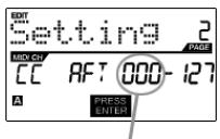
Minimum range field
Minimum Range field
This field is used to specify the minimum value that the afttouch will transmit.
- Use [<] or [>] button to select Minimum Range field.
- While in Minimum Range field, turn [VALUE] dial to select desired minimum aftertouch value.
- Use the [> button to select the next field.
Maximum range field
Maximum Range field
This field is used to specify the maximum value that the afttouch will transmit.
- Use [< ] or [>] button to select Maximum Range field.
- While in Maximum Range field, use [VALUE] dial to select desired maximum aftertouch value.
TIP!
Sometimes you might not want the full 0-127 range of control that a slider automatically defaults to. Often, reducing the value range of the slider might actually give you more precise control over the parameter it is controlling.
For example, if you are using one of the sliders to control a syncsed delay line, there might only be about 10 available values for the sync delay time (1/2, 1/4, 1/8 note, etc.). Therefore, it wouldn't make much sense to have the slider transmit the full 128 MIDI control values, since that only gives you a tenth of the full slider range. Instead, try setting the maximum value of that slider to 10 and you will see how much more precise control this allows you to have.
TIP!
Setting the maximum value of a controller lower than the minimum value will cause the knob or slider to behave inversely.
For example, if you are controlling an interface or plug-in that operates with a drawbar structure, such as organ instruments, it might be more intuitive to invert your sliders.
GLOBAL MODE
Pressing the [GLOBAL] button calls up GLOBAL MODE. In this mode, you can send global messages and make general changes to the way that your MPD24 functions, including:
| KILL MIDI | Page 1 |
| MIDI COMMON CHANNEL | Page 2 |
| LCD CONTRAST | Page 3 |
| PAD SENSITIVITY | Page 4 |
| PAD VELOCITY CURVE | Page 5 |
| SAVE GLOBAL | Page 6 |
| SYSEX TX | Page 7 |
| VERSION | Page 8 |
In this mode, you can modify each of these parameters by scrolling to the correct edit page with [<] and [>] buttons.
KILL MIDI - Page 1
KILL MIDI allows you to send either an ALL NOTES OFF message on each MIDI Channel or a RESET ALL CONTROLLER'S command.
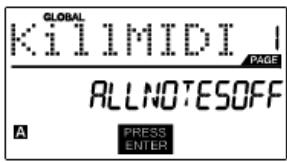
ALL NOTES OFF is a special MIDI message used to turn off any notes that might be playing on the MPD24. It is often used to recover from erroneous stuck notes. Sometimes an ALL NOTES OFF command can be used to stop an instrument from sounding before some specific commands are issued, such as program change commands.
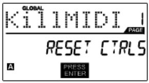
RESET ALL CONTROLLERs is a MIDI message used to return all values such as pitch bend, modulation, and aftertouch to their default settings. It is not uncommon in live performance and/or complex sequencing for one or more controllers to be left in a state that can cause the next patch or program to sound strange. Control reset will return all values to their default settings.
- Press [GLOBAL] button, KILL MIDI will be the first option that appears on the screen.
- Turn [VALUE] dial to select either an ALL NOTES OFF or a RESET ALL CONTROLLER'S message.
- Press [ENTER] to transmit the message.
MIDI COMMON CHANNEL - Page 2
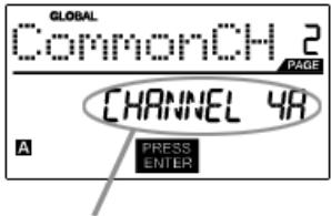
Assign MIDI Common
Channel in this field
You can assign the MIDI Common Channel to a desired MIDI Channel. Any and all pads, knobs or sliders assigned to the MIDI Common Channel (C) will transmit MIDI information via the channel number that you select in this field.
- While in GLOBAL MODE, use [>] button to scroll to MIDI Common Channel.
- Turn [VALUE] dial to select desire MIDI Channel.
- Press [ENTER] set MIDI Channel.
Note: If you change which channel the MIDI Common Channel is using, you also need to set any device that is controlled by the Common Channel to that channel number as well.
LCD CONTRAST - Page 3
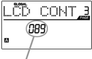
Adjust contrast
in this field
The contrast of the LCD screen can be adjusted for optimal viewing.
- While in GLOBAL MODE, use [> button to scroll to LCD CONT.
- Turn [VALUE] dial to select a contrast level. Possible values are 0 - 100% .
- Press [ENTER] to select desired contrast level.
PAD SENSITIVITY - Page 4
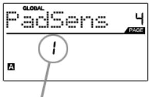
Adjust Pad Sensitivity in this field
PAD SENSITIVITY allows you to adjust how sensitive the pads will be to the touch. Adjust this setting if you find it hard to achieve maximum velocity when you hit the pads hard, or if you are getting high velocities when you hit softly.
If the Pad Sensitivity number is set to low number, it's harder to get a high velocity value even if you hit a pad hard. If the Pad sensitivity number is set to high number, it may become too easy to get high velocities even when you hit a pad softly.
- While in GLOBAL MODE, use [>] button to scroll to PadSens.
- Turn [VALUE] dial to change Pad Sensitivity number.
- Press [ENTER] to select desired sensitivity.
PAD VELOCITY CURVE - Page 5
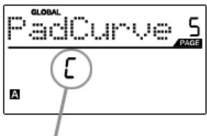
Adjust pad curve in this field
A PAD VELOCITY CURVE describes how your MPD24 is outputting MIDI velocities when you hit a pad, based on a certain ratio of the input / output velocity that characterizes the particular curve. The Pad Velocity Curve feature is intended to help you customize and adjust your MPD24 to your particular playing style and can add expressivity and control to your performance. If you find it difficult to achieve a comfortable velocity range for your playing style (you can not get a velocity of 127 even if you hit the Pad very hard, or vice versa, you get velocity 127 easily even if you hit the Pad softly) you can adjust the velocity curve as desired.
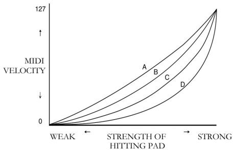
- In GLOBAL MODE, use [> button to scroll to PadCurve.
- Turn [VALUE] dial to select one of the four curves - A, B, C, or D.
- Press [ENTER] to select desired curve.
SAVE GLOBAL - Page 6
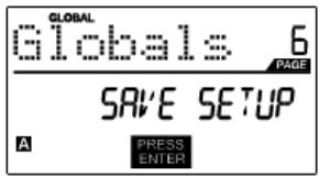
SAVE GLOBAL allows you to save all of the global parameters on the MPD24, including LCD Contrast, Pad Velocity Curve, Pad Sensitivity, MIDI Common Channel, Preset and SysEx information.
When you optimize the MPD24 to best suit your performance, you should use this option to save all of these settings so they will automatically be loaded next time you turn on the MPD24.
- While in GLOBAL MODE, use [>] button to scroll to Globals. You will see 'SAVE SETUP' displayed on the screen.
- Press [ENTER] to save all the global settings on the MPD24.
SYSEX TX - Page 7
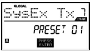
SYSEX TX allows you to transfer Preset data from the MPD24, including Controller Numbers, MIDI Channels and various other parameters via SysEx.
- While in GLOBAL MODE, use [> button to scroll to SysEx Tx.
- Use the [VALUE] dial to select which preset's information you would like to transfer.
- Press [ENTER] to transfer the preset data via SysEx to the MIDI/USB port.
SysEx transfers to the MPD24
You can also load preset data into the MPD24 from an external source by "playing" a SysEx file into the MPD24. This can be done with a variety of SysEx applications, many of which are widely and freely available over the Internet.
- Make sure that the device is connected to the MPD24 either via the USB or the MIDI IN port.
- Make sure that you are in Preset Mode.
- "Play" the SysEx file on your external device or computer.
Please note that when transferring SysEx information into the MPD24, the data will override the data of the original Preset which was sent to your SysEx editor. For example, if you transfer Preset 5 to your SysEx editor and then send it back to the MPD24, the data will overwrite Preset 5.
VERSION - Page 8
VERSION allows you to see what version of the operating system and firmware is currently loaded onto the MPD24.
While in GLOBAL MODE, use [>] button to scroll to Ver for version information.
PROGRAM CHANGE MODE
What is Program Change?
A Program Change, often referred to as a Patch Change, is a MIDI message used for sending data to devices to cause them to change to a new program. This allows you to tell a hardware or software device which sound to play. For example, if your MPD24 is controlling a rock drum kit on your DAW or an external device, using a Program Change command allows you to easily switch to an electronic kit. This gives you the freedom to re-orchestrate any MIDI content without having to redo any MIDI note information.
Pressing the PROGRAM CHANGE key calls up PROGRAM CHANGE mode.
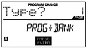
There are two different selectable types of Program Change on the MPD24:
| PROG CHANGE | This event will transmit a regular Program Change message (0-127) to your DAW or an external device, allowing you to switch between 128 different program banks. |
| PROG+BANK | This event transmits a Program Change message (0-127), along with a Bank L (Least Significant Bit) Change message (0-127) and a Bank M (Most Significant Bit) Change message (0-126), which allows access of up to 16384 different program banks. You can use PROG+BANK if your DAW or external device supports LSB and MSB. |
Turn [VALUE] dial to select either a PROG CHANGE or PROG+BANK event.
PROG CHANGE (Program Change)
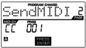
PROG CHANGE allows you to transmit a regular Program Change message.
- Select PROG CHANGE with [VALUE] dial.
- Press [ENTER] to see the next page of parameters.
- You can select program number by turning [VALUE] dial (1...127).
- MIDI CH field shows current Common MIDI Channel. You can access MIDI CH field by pressing [<] button and change it with [VALUE] dial. You can move between PROG field and MIDI CH field with [<] and [>] buttons.
- Press [ENTER] to send the Program Change message.
PROG+BANK (Program Change with Bank Change)
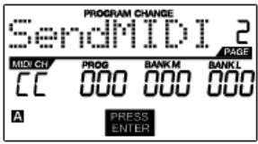
PROG+BANK allows you to send a Program Change with Bank Change message to your DAW or external sound module.
- Select PROG+BANK with [VALUE] dial.
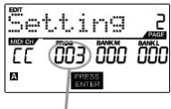
- Press [ENTER] to see the next page of parameters.
You can move between the fields with [<] and [>] buttons.
- Select desired Program Change number by turning [VALUE] dial in the PROG field.
- Select MSB (Most Significant Bit) by turning the [VALUE] dial in the Bank M field
- Select LSB (Least Significant Bit) by turning the [VALUE] dial knob in the Bank L field
- Press [ENTER] to send the Bank and Program event.
SPECIFICATIONS
| GENERAL | |
| Display | custom LCD w/ backlight |
| Dimensions (WxDxH) | 318mm x 283mm x 50mm (68mm MAX) |
| Weight | 2.18 kg |
| Power | ~200mA, 5V DC via USB ~500mA, 6V DC via external adaptor (MP6-1) |
| Number of Presets | 30 |
| MIDI output channels over USB | 48 (16 channels x 3 ports) |
| MIDI output channels from 5-pin MIDI | 16 |
| Drum pads | 16 (velocity and pressure sensitive) |
| Drum pad banks | 4 |
| Slides | 6 |
| 360 degree knobs | 8 |
| Accessories | • User's manual • USB cable (1m) • CD-ROM disc with Uniquest Editor and other extras • DVD-ROM disc with BFD Lite |
| INPUTS/OUTPUTS | |
| MIDI inputs | 5-pin DIN x 1 |
| MIDI outputs | 5-pin DIN x 1 |
| USB | Slave connector x 1 (MIDI over USB) |
| DC IN | 6V DC, 500mA |
INDICE
INTRODUCCION 31
CHARACTERISTICAS PRINCIPALES 31
CóM O N A V E G A R EN M O D O E D I T:
REW,FF,STOP,PLAY,RECORD
Unanota sul MIDI Common Channel (CC)
Campo Program Change
In Anything, I would like to say that the number of people in this room is 10.
Il Banco M describes the part of information in a way that is more or less similar to the one described in the previous paragraph.
This field is used to specify the maximum value that the afttouch will transmit.
EDIT MODE (Édition) 103
TOUCHESREW,FF,STOP,PLAY,RECORD
PREVIEWING (VISUALISATION)
USB cable not connected:
REW,FF,STOP,PLAY,RECORD
NOTE AFTERTOUCH (Channel Pressure)
- KEY FEATURES
- COMPUTER REQUIREMENTS
- TOP PANEL OVERVIEW
- ASSIGNABLE CONTINUOUS CONTROLLER SLIDERS
- MPC-STYLE PRESSURE AND VELOCITY SENSITIVE PADS
- NAVIGATION / MENU DISPLAY SECTION
- NAVIGATION/CONTROL BUTTONS
- ASSIGNABLE CONTINUOUS CONTROLLER KNOBS
- TRANSPORT CONTROL BUTTONS
- REAR PANEL OVERVIEW
- DC POWER INPUT
- KENSINGTON LOCK
- USB CONNECTOR
- MIDI OUT CONNECTOR
- MIDI IN CONNECTOR
- HOOKUP DIAGRAM
- A NOTE ABOUT USING THE MPD24 WITH SOFTWARE:
- IMPORTANT:
- SCENARIO 2
- NAVIGATION AND CONTROL BUTTONS EXPLAINED
- PRESET
- EDIT
- GLOBAL
- VALUE (Push To Enter)
- IMPORTANT TIP!
- [ \left[ < \right] \text{and} \left[ > \right] \text{BUTTONS} ]
- PAD BANK
- PREVIEW
- FULL LEVEL
- LEVELS
- TRY IT!
- PROGRAM CHANGE
- REW,FF,STOP,PLAY,RECORD
- MIDI MACHINE CONTROL (MMC)
- DISPLAYING INFORMATION
- NOTE
- NOTE AFTERTOUCH (Channel Pressure)
- CONTROL CHANGE
- CONTROL AFTERTOUCH
- MIDI MACHINE CONTROL COMMAND (MMC)
- MIDI MACHINE CONTROL (MMC) is
- PREVIEWING
- THE ADVANTAGES OF PREVIEWING
- MODES
- Preset Mode -
- Edit Mode -
- Global Mode -
- PRESET MODE
- What is a Preset?
- Page 1 - Load Preset
- Page 2 - Save/Copy Preset
- Page 3 - Name Preset
- EDIT MODE
- HOW TO NAVIGATE THE EDIT MODE:
- REMEMBER!
- Editing Pads
- What is a Note Message?
- What is a Program Change?
- SELECTING PAD EVENT TYPE:
- A Note on MIDI Common Channel (CC)
- NOTE - PARAMETERS
- MIDI Channel field
- Note field
- Play Mode field
- Pressure field
- PROGRAM CHANGE - PARAMETERS
- Program Change field
- Bank M
- Bank L
- Note:
- Editing Knobs and Sliders
- What is Control Change?
- What is Aftertouch?
- SELECTING KNOB OR SLIDER EVENT TYPE:
- CONTROL CHANGE - PARAMETERS
- Control Change field
- Minimum Range field
- Maximum Range field
- AFTERTOUCH - PARAMETERS
- TIP!
- GLOBAL MODE
- KILL MIDI - Page 1
- MIDI COMMON CHANNEL - Page 2
- LCD CONTRAST - Page 3
- PAD SENSITIVITY - Page 4
- PAD VELOCITY CURVE - Page 5
- SAVE GLOBAL - Page 6
- SYSEX TX - Page 7
- SysEx transfers to the MPD24
- VERSION - Page 8
- PROGRAM CHANGE MODE
- What is Program Change?
- PROG CHANGE (Program Change)
- PROG+BANK (Program Change with Bank Change)
- SPECIFICATIONS
- INDICE
- INTRODUCCION 31
- CHARACTERISTICAS PRINCIPALES 31
- CóM O N A V E G A R EN M O D O E D I T:
- Unanota sul MIDI Common Channel (CC)
- Campo Program Change
- TOUCHESREW,FF,STOP,PLAY,RECORD
- PREVIEWING (VISUALISATION)
Brand : AKAI
Model : MPD24
Category : MIDI Controller