
STEP 570 X - Jigsaw AEG - Free user manual and instructions
Find the device manual for free STEP 570 X AEG in PDF.

| Product Type | Electric jigsaw |
| Brand | AEG |
| Model | STEP 570 X |
| Power Input | 570 W |
| No-load Stroke Rate | 450-3000 min⁻¹ |
| Stroke Height | 19 mm |
| Max. Cutting Depth (soft wood) | 95 mm |
| Max. Cutting Depth (wood) | 65 mm |
| Max. Cutting Depth (steel) | 8 mm |
| Max. Cutting Depth (aluminum) | 10 mm |
| Bevel Cut | Up to 45° |
| Weight | 2.1 kg |
| Power Supply | Single-phase AC, double insulation |
| Noise Level | 82 dB(A); during operation >85 dB(A) |
| Vibration | 4 m/s² (acceleration) |
| Blade Change | Tool-free quick-clamp (clamping lever) |
| Pendulum Action | Yes, adjustable |
| Dust Extraction Connection | Inner diameter 30 mm |
| Splinter Guard | Yes, removable |
| Maintenance | Annual brush inspection recommended |
| Safety | Double insulation, residual current device recommended, safety glasses mandatory |
| Spare Parts | Use only AEG parts |
| General Information | Complies with EN 50144, EN 55014, CE directives |
Frequently Asked Questions - STEP 570 X AEG
User questions about STEP 570 X AEG
0 question about this device. Answer the ones you know or ask your own.
Ask a new question about this device
Download the instructions for your Jigsaw in PDF format for free! Find your manual STEP 570 X - AEG and take your electronic device back in hand. On this page are published all the documents necessary for the use of your device. STEP 570 X by AEG.
USER MANUAL STEP 570 X AEG
STEP 570 X STEP 600 X
Instructions for use Please read and save these instructions.
D Gebrauchsanleitung Bittle lesen und aufbewahren.
F Instruction d'utilisation Priere de dire et de conserver.
Istruzioni d'uso Si prega di leggere le istruzioni e di conservarle.
E Instrucciones de uso Lea y conserve estas instrucciones por favor.
P Instruções deServiço Por favor leia e conserve em seu poder.
NL Gebruiksaanwijzing Lees en let goed op deze adviezen.
DK Brugsanvisning Vær venlight at læse og opbevare.
s Bruksanvising Var god Ias och tag tillvara dessa instruktioner.
FIN Käyttoohje Lue ja sailytö
TR Kullanim kilavuzu Lutfen okuyun ve saklayin
RUS HNcTpkykuzna no NcNoJIb3OBAHHIO PoXaJyIcTa, npOHTnte n COxpaHnTe NaCToAuYIO HHcTpyKzNU
| You are demanding and expect to purchase quality goods - quality offered by Atlas Copco. We have built a durable and reliable electric power tool for you. Please read the instructions for use before first operation so you can handle your power tool effectively and safely. We are sure that buying an AEG Electric Power Tool from Atlas Copco was the right choice! | |
| Technical Data | STEP 570 X STEP 600 X Cutting depth max. in: Soft- wood 95 mm 110 mm Hard-wood 65 mm 70 mm Steel 8 mm 8 mm Aluminium 10 mm 15 mm Nominal power 570 W 600 W Stroke rate under no-load 450-3000 min-1 450-3000 min-1 Lengths of stroke 19 mm 19 mm Bevel cuts up to 450° 450° Weight 2,1 kg 2,1 kg |
| Advice for your safety | Please pay attention to the safety instructions in the attached leaflet! Dust that arises when working on material containing asbestos or stonework containing crystalline silicic acid is harmful to the health. Please follow accident prevention regulations. Appliances used at many different locations including open air must be connected via a current surge preventing switch. Always use the protective shields on the machine. Always disconnect the plug from the socket before carrying out any work on the machine. Always wear goggles when using the machine. It is recommended to wear gloves, sturdy non slipping shoes and apron. Sawdust and splinters must not be removed while the machine is running. Do not pierce the motor housing as this could damage the double insulation (use adhesives). Keep mains lead clear from working range of the machine. Always lead the cable away behind you. Only plug-in when machine is switched off. Dust that arises when working on wood or using the tool on industrial material can be dangerous to health. In this case connect the tool to a suitable suction device. Do not use cracked or distorted saw blades. |
| Measured sound value | Typically the A-weighted sound pressure level of the tool is 82 dB (A). The noise level when working can exceed 85 dB (A). Wear ear protectors! Measured values determined according to EN 50 144. |
| Measured vibration value | Typically the weighted acceleration is 4 m/s2. Measured values determined according to EN 50 144. |
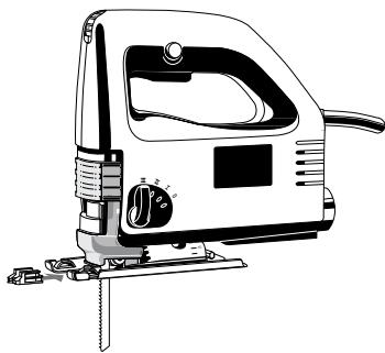
| Use | This jig saw can cut wood, plastic and metal; it can cut straight lines, bevels, curves, and internal cut-outs. Do not use this product in another way as stated for normal use. |
| Mains connection | Connect only to a single-phase AC current supply and only to the mains voltage specified on the rating plate. Connection to sockets without earth protection is possible as the appliance features protective insulation to DIN 57 740/ VDE 0740 and CEE 20. Radio suppression complies with the European standard EN 55014. When fitting the plug, make sure that the brown (live) wire of this appliance is connected to the plug terminal marked L or coloured red, and the blue (neutral) wire of this appliance is connected to the plug terminal marked N or coloured black. Under no circumstances must the wires of this appliance be connected to the earth terminal of the plug marked either E, with the earth symbol or coloured green or green/yellow. |
| ENGLISH | 1 STEP 570 X, STEP 600 X |
Brief description
The stroke-rate (= movements per minute of the saw blade) can be infinitely varied by means of the adjustment wheel.
Transparent cover for optimum sawdust removal.
The sawdust blower removes sawdust ahead of the cut - very practical when sawing along a line.
The vibration damper permits quieter running by means of a counterweight on the plunger.
The saw blade can be changed in seconds by using the tension lever.
The base plate can be tilted to both sides by 45^ for bevel cuts.
The anti-splintering device almost entirely prevents the edge of the wood from splintering.
The built-in pendulum stroke improves the cutting performance. The pendulum stroke of the saw blade means it is only pressed against the material on the reverse stroke (working stroke) and lifted off the material on the forward stroke.
Result: better extraction of sawdust, lower friction higher cutting performance.
The pendulum stroke can be adjusted by the pendulum stroke control and thus adapted to different kinds of material.
The on-off switch is shaped in such a way that it can be used from the forward or the rear holding position.
The on-off switch can be fixed in the "On"- position for continuous operation by means of the locking button.
Integrated suction channel for connection to a vacuum-cleaner.
Integrated tool storage for spare blade.
Modifications: Text, diagrams and data are correct at the time of printing. In the interest of continuous improvement of our products, technical specifications are subject to alteration without prior notice.
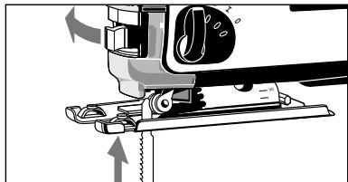
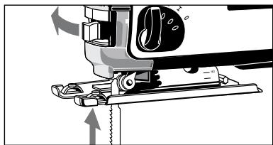
Inserting the saw-blade

Always disconnect the plug from the socket before carrying out any work on the machine.
- Push the tension lever as far as it will go, as shown in the illustration.
- Fit the saw blade into the groove in the support roller and push it firmly into the plunger as far as it will go; the lug of the saw blade must be in the plunger (see illustration).
- Release the tension lever and the saw blade is gripped automatically.
- Check that the saw blade fits firmly (wear protective gloves!); the slot in the plunger must always be at an angle to the saw blade (see illustration below).

When fixing the saw blade it might be in a slightly sloping position.
When first cutting it will adjust automatically.

| Adjusting the base plate | The base plate can be tilted or moved backward or forward. Setting an angle => For angle cuts and bevels. Loosen the fixing screw, pull the base plate out of the mounting, set it at the required angle (15°, 30°, 45°), push it back into the mounting and tighten the fixing screw again. Angles other than 45° can be set by not pushing the base plate back into the mounting. The angle can be read off the scale. For very exact angle cuts it is recommended to make a test cut. Moving the base plate => For plunge cuts or cuts in corners. Loosen the fixing screw, push the base plate to the rear and tighten the fixing screw again. The base plate in this position is fixed at the 0° setting. Moving back => For cutting a hole with a short saw blade and sawing near the edge. Take the fixing screw out, push the base plate to the rear and screw the fixing screw tightly into the rear hole. In this position the base plate can also be off-set in longitudinal direction. | |
| Sawdust removal | Only operate the machine with suitable sawdust removal. The integrated suction channel has the standardized internal diameter of 30 mm. Use the suction hose (Id. No. 4932 3304 12) from our range of accessories to connect it to a household vacuum cleaner or to an wet-and-dry vacuum cleaner. | |
| 1. Push in and turn the suction hose into the suction channel until it fits firmly. | ||
| 2. Push the transparent cover downwards to ensure optimum sawdust removal. | ||
| Anti-splintering device | The anti-splintering device almost entirely prevents the edge of the wood from splintering. Place the anti-splintering device as shown in the illustration with the smooth side downwards and flush with the base plate (this is only possible with the base plate in the forward position). | |
| Adjusting the stroke rate | The stroke-rate (= movements per minute of the saw blade) can be infinitely varied by means of the adjustment wheel. The letters A to G are printed on the speed control, meaning: A = lowest stroke rate G = highest stroke rate | |
| ENGLISH | 3 | STEP 570 X, STEP 600 X |
| The stroke rate appropriate to the material being worked on can be taken from the following table, and the corresponding letter shown on the setting wheel. | ||
| Material | Stroke rate | |
| Wood | G | |
| Steel | D-E | |
| Aluminium | D-E | |
| Rubber | A-C | |
| On-off switch | Intermittent use Switching on: Press On-/off switch Switching off: Release On-/off switch | |
| Continuous use Switching on: Press the On-/off switch and then the locking button, after that release on-off switch. Switching off: Press the On-/off switch and then release. | ||
| Adjusting the pendulum stroke | By adjusting the pendulum action the cutting depth of the saw blade teeth is increased or decreased. As a rule of thumb: Soft material Large pendulum stroke Hard material Small or no pendulum stroke Clean cut surface No pendulum stroke The appropriate degree of pendulum effect can be taken from the following chart and compared with the marking at the pendulum stroke lever. | |
| Material | Degree of swing action | |
| Wood | I - III | |
| Plastic | I | |
| Aluminium | 0 - I | |
| Steel | 0 | |
| Ceramics | 0 | |
| Rubber | 0 | |
| The stroke rate shown in the chart is only a suggestion for your general guidance! | ||
| The stroke rate can be set on the stroke rate control even while the motor is running. | ||
| Advice for operation | 1. | Set the stroke and pendulum stroke according to the material to be cut. |
| 2. | Position the machine with the front part of the base plate on the material, and switch on. | |
| 3. | Press the machine downwards onto the material and guide it along the cutting line. | |
| Hints | Do not press down too hard on the piece you are cutting. Light pressure on the saw blade is sufficient to achieve the optimum rate of sawing. When cutting along a score line, use the marking on the anti-splintering device as an optical guide. To obtain a perfectly straight cut, clamp a strip of wood as a guide along the material or use the parallel guide (accessory). For cutting at an angle, or cutting a bevel, adjust the base plate. For sawing close to the edge, set the base plate at its rearmost position. | |
| ENGLISH | 4 | STEP 570 X, STEP 600 X |
| Sawing sheet metal | To avoid vibration, clamp metal sheets onto a wooden base. To saw metal, use cooling agents along the cutting line (oil, white spirit). | |
| Plunge cuts | Plunge cuts without pre-drilling a hole are possible with soft materials (wood, light building materials for walls). Harder materials (metals) must first be drilled with a hole corresponding to the size of the saw blade. Move the base plate to the rearmost setting in order to obtain the best possible cutting angle for starting the cut.(see section "Adjusting the base plate") | |
| 1. | Set the pendulum stroke at the pendulum stroke control to "0". | |
| 2. | Without switching the machine on, place it with the front edge of the base plate on the cutting point. | |
| 3. | Switch the machine on and carefully lower the saw blade already running into the material. | |
| Parallel guide and circle cutting guide (Accessory*) | Using the parallel guide or circle cutting, parallel cuts of 0–200 mm, circular cuts of 100–400 mm are possible. Use cross-cut saw blades. *Not included in standard equipment, available as an accessory. | |
| Assembly of parallel guide | Push the parallel guide, with the contact surface facing downwards, through the lugs in the base plate and fasten it in position with the capstand-headed screw. For cutting from the left or from the right, push the parallel guide in from the appropriate side. | |
| Cutting a circle | Push the parallel guide, with the contact surface facing upwards, through the lugs in the base plate and fasten it in position with the capstand-headed screw. Tighten the centre point into the parallel guide from the top. Ensure that the saw blade and the circle centre point form one single line. Further accessories with part numbers are shown in our catalogues. | |
| Maintenance | In order to guarantee constant readiness for operation, the machine should be checked for worn carbon brushes at one of the AEG after-sales service agencies. Use only AEG accessories and spare parts. Should components need to be replaced which have not been described, please contact one of our AEG service agents (see our list of guarantee/service addresses). If needed, an exploded view of the tool can be ordered. Please state the ten-digit No. as well as the machine type printed on the label and order the drawing at your local service agents or directly at: Atlas Copco Electric Tools GmbH, Postfach 320, D-71361 Winnenden. | |
| ENGLISH | 5 | STEP 570 X, STEP 600 X |
BCTpoeHHb KaHAn IJn OTCocA Jn POKIOUeHn K nbIneCocy.
BCTpoeHHbI KapMaH dIJI 3aIacHO rIe3BnI.
MOnnFikauN: TekCT, nIJIIOCTpaunu N daHbIe BepHbI H MaOMeHT BbXOaM3 neHATu. B INTEpeCax NOCToHHORU yCOBepueHCTBOBaHIN HaUNs N3dEJIIN, TEXHNcckNe XapAKTePNCtKN MOrYT N3MeHrTaBc6e3 npEdBaPntelHoRTO YBEDoMJeHNA.
Bctabka NINJbHbIX NOJOTeH.

Ipeed BbInOJIHeHnEM KaKnx-JIb6o pa60 IIO O6CJyXnBaHNIO INCTpyMeHTa BCErDa BbIHMaTe BNJKy N3 pO3ETKN.
- OTTJHnTe HATJXHOI pbIar Do yNopa, KAK NOKa3aHO Ha IJIIOCTpaUIN.
- BCTaBbTe PnIky B UeIb B POnIdepXnBaIOUeM pOInke BDbINHbTe ee B PnIyHKeD OyNopa; XBOcTobNK PnIky doJxeh 6bTb B PnyHxpe (CM. mJIJIocTpaIIO).
- OTnyCTnTE HaTJXHOI pbHar I nnJIka 6yJeT aBTOMaTnueCKN 3aKaTa.
- Поберъп, что плк сиит почно (надьт e 3auntbte nepuATkn!); пореть в пунже дохна BCERДа Бытб по улOM K плк (СM. nJIIOCTpaUNHnke).

PnФKcnpoBaHn NIIJKN OHa MOKeT HxOAnTbCnB CJERKa HAKJIOHEHHom NOJIOXeHn.
Pn nepBOM NJIeHN OHa BbIPOBHReTcR ABTOMaTIuCHEKn.

| Ochobahne moxho haklohntb ny CdBHytb ha3ad ny Bnpeed. | |
| Yctahobka pod yrlom → Дду ytlOBbixи n HacIohnbix cpe3OB. | |
| Oclabte ФиксypuOoiBn BVHT, BvITaHte OCHOBAHne n3 depxaTeJIy, yctahobite ergo na Tpe6byeMby yrol (15°, 30°, 45°), BCTabte o6paTHo B | |
| depxaTeJIy n CHOBa 3atAHNTe ФикspuOoiBn BVHT. Yblb, OTmUHbte OT 45° | |
| MORYT b6bTy bYCTAHOBLeHbI, eCInNe He BCTABJYbTb OCHOBAHne o6paTHo B | |
| depxaTeJIy. | |
| YrOJ POKAZAH Ha 6kAJIe. | |
| Дду ouChb ToCHOrOу YTLOBOrO pIIeHnry | |
| peKOMeHdyeTc npOn3BeCTn npO6bHbI | |
| пелмешени OCHOBAHN → Дду | |
| Bpe3AHn IIN pe3AHn B yrlax. | |
| Oclabte ФикspuOoiBn BVHT, | |
| ToIkhNtE OCHOBAHne Ha3ad n ChOBa | |
| 3atAHNTe ФикspuOoiBn BVHT. | |
| OCHOBAHne B 3tOM pIoOxHeHn | |
| ФикspuYetc ha 0°. | |
| Пелмeшени Ha3aD → Дду | |
| Blype3AHn OTBepCTM KOPOTKIM NOLOTHOM I PIIeHnry OKOLO KpOMKn. | |
| Blype3AHn ΦикspuOoiBn BVHT, TOILKHTE OCHOBAHne Ha3aD N BVBHTHte Do | |
| ynopRa ФикspuOoiBn BVHT B 3aDHee OTBepCTne. | |
| B 3tOM pIoOxHm OCHOBAHne MOpKeT | |
| ТAKKE b6bTy CMeUeHn B pIOOJIbHOM | |
| Haprableni. | |
| Осoc stpykkn | ИсpoьзуITE ИСТРУМЕТ TOLБКо C COOTBETCTBvOUIM yCTPoyCTBOM Дду OTCOCa STpykkn. |
| ВстpoEHну OTCsBaIooIki KaHaN MeeT StAnDapTNbI BHyTpErHNN DiAmETrp 30 MM. ПлбЗуTecb OTcAsBaIooIkl ShIaHROM (Apt. No. 4932 3304 12) ИЗ наSteero accoPTUMeHTHO prJa akCEccSyarOB Dду писоEdINHЯ K b6tOBOMy O6bIHyOMу IIN "BvIaxHOM" nbIleCocSy. | |
| 1. BCTabte shaHr B OTcAsBaIooIki KaHaN I nobERpHnTe erO do npOchoro 3akpenIeHn. | |
| 2. CdbNVbte BHN3 npOzPauHyOkbIshky dJa obEsceHEny ONTImaJIbHOr OblTeOTcoca. | |
| YcTPOIcTBO прOTIN pacsePllenHg КрOMok pa3pe3a | ПрсncO6bLHneпрOTIN pacTeCKIBaHnI NaOITI pOJIHOCTbIg прEDOTBpaUaAeT packaJIbBaHnE KpOMKn depeBa. |
| YcTahOBHte yCTpoyCTBO рОТИB pacSeIeHnY KpOMK pa3pe3a Кak пОКЗaHNoHa nIIJIIOCTraIg - rIaIckOI STOpOHo BHN3 n 3aIodIaIcO C OCHOBAHmE (3TO B03MOXHO TOLbKO KorDa OCHOBAHne haoDmitcB B пepeHem pIoOxHmI). | |
| PyCCKN | 58 |
| PergunpoBka частоыхoda | Частоахoda (= колочецво песмени полоть в минуту) Может сны палови посpeядстом рergлировочог кoleска. Бухсы с А по G наесенные на perуларсokорoctи ознают: A = наименьшая скорoctьхoda G = набolyшая скорoctьхoda |
| Частоухoda, которay похodит К образываемου матералу, можно узать иЗ сладуочи таблцы и установпь на рergлировочог кoleске соотberгстуюшу boу bukby. | |
| Мaterиал частоахoda | |
| Дерево G Стоь D-E Алиониь D-E Рezина A-C | |
| Выковочел "On-Off" ("Вкл./Выкл.") | Выковочны: нажать курковы Выковочел Одлесочны: отneyсты курковы Выковочел Длenteьная робота: Выковочны: нажать выковочны "On-Off"( "Вкл./Выкл.")и заlem фikсирочую коньу, поlete оторo otnyсты выковочны "On-Off" ("Вкл./Выкл.").Одлесочны: нажать и заlem отneyсты Выковочел "On-Off"( "Вкл./Выкл."). |
| PergunpoBka маянково хoda | PeruginpoBanie Маянковоухoda уBELINCHBAETCSУИУMeHbSAETCS сокорstь двиненья.Кak павлио: Мягkin мaterиал Бolyшо маянковыхoda Тердь мaterиал МаянковыхOD маленький Или OTКLOCHITb Сobcem Для пеленя бeз pacseлени поberpxhoctи маянковыхOD OTKLOCHITb Соотberгстуюше 3纳чени маянковоухoda можно узать ИЗ ножеследуншей tabлцы и сравн'tь с по��ааняmaи на поеклоча themselves маянковоухoda. |
| Мaterиал Маянковыхoda | |
| Дерево I - III Пл actik I Алиониь O - I Стоь O Керампka O Peэина O | |
| Длиахoda, указаннaya в tabлцие, Явяясят с тлько cobetOM对于我们 obsegero pukoBoDCTBa! | |
| Длиухoda можно установьать пегklочаелем доже рrips работаюшем MOTOpe. | |
| PyCCKN | 59 |
| Советibles no эксплуаташи | 1. установские скорочь и маятейковский xod в COOTBETCTBи C MaTePnauJOM, КOTOBiydoJIeH6bIb pa3pe3aH. |
| 2. Росторожite Машину поеддем кромковocochobamna Ha obpa6aTbBaembl MaTePnau N BkJIIOUHTe MaShInuY. | |
| 3.ПробмITE Машину К MaTePnauNу И ВEDITe BdoJIb Llinni pe3a. | |
| Советibles | He haximai Te cnLsKOM cnLbHo Ha deTaJIb, KOTOPU BO bI pINlte. Лergoro daJIbENHHa NoIOTHO pINLKIN DoCTaTOH DoI DaOCTIXEHN OINTIMALBOHOro ПИЕн�Я ПО pa3MeTOHoi Llinni PONL3yIeTceb MeTKO HA yCTPOIcTBe потINB pa5UePILHry KpOMOK B KaueCTBE BV3ayIbHO HaprabLIAOIOsei. ДЯ пОуEHN NO COBepSEHNO prIyMOrO paCpNIa 3akpeNTe DepeBHyHyo ПлAnKBy B KaueCTBE HAprabLIAOSeI BdoJIb MaTePnAra IINI INCpOJIb3yIte пapalJIbHyIO HAprabLIAOIOU (akCEccSyAP). |
| ДЯ пОLEHЯ NOI yIOM IINI PhACKIy OTpeRyIpyte OCHOBAHne. ДЯ пОLEHЯ 6bI3KO K KpOMKe UCTAHOBITE OCHOBAHne B erO kraiHem 3aHem ПОLOXeHn. | |
| Во nb6Exahne Bv6paIzno 3akpeNTe LiST MToAIIa Ha DepeBHyHOM OCHOBAHn. Пri pIleHn MaTALNa IcNoJIb3yIte OxJaJDAIOUIne JxIDKOCSTI BdoJIb Llinni pacnla (Maclo, yaiT cIpynt). | |
| Вразанes B maTePnau | Вразанes 6e3 PreDVBapITeHBO RbICBepLIbVAHnRA OTBecTnB Bo3MOxHOb MЯrkx MaTePnauIax (depeBE, leKxN CTPOITeBly MaTePnauIax DnI CTeH). B БОJOe TbePdIb MaTePnauIax (MetAlNe) Heo6XoDMIO ChauIa IpoCBePIITb OTBecTnA, COOTBETCTBHyOIOpe pa3Mepy PInlBHO rOIOTHa. РepeDbIVbTe OCHOBAHne B KpaIeHee 3aDHee PONOxHene DnI PONUeHnRA HAmUyIeOу YrIa pe3AHn Prn HauJIe PInIeHn.(CM. pa3dJIe "PeryIipOBKa OCHOBAHn") |
| 1.УstANOBITE MAATHIKOBY XOD Ha erO peRyJIaTOpe Ha "0". | |
| 2. He BkIIOUa MaSHIny pa3MeCTHte ee pepeHne KpOMKo OCHOBAHnHa ToUke ПИeHnry. | |
| 3.ВkIIOUHTE MaSHIny I OCTOPOXHO NORpykaIte DBVIXUOIOSt PInIky B MaTePnau. | |
| Наравлиюа я за napallenbHoro mIoHnry i dlya ПИeHnry okpyxHocTei. (DonolHIneIb- hЯ рinad- лжHOCtB*) | ИсpoЛьзу princspocoblenia ДЯ napallenbHoro PInIeHnRA I ByIpnlmbaHnRA okpyxHocTei, Bo3MOxHO napallenbHbIe pe3b IIupinOH 0-200 MM, KpyroBlye pa3pe3b DiIaMeTpOM 100-400 MM. ИсpoЛьЗуITE PInIckIЯд пОпepeHoro PInIeHnry. *В.staIapTHyIO KOMIeKtaIciuI Ho BxOJIT, nOCTaBlIeTcB KaueCTBe dOnolHIneIbHoy рinIaNDEKHOCTN. |
| PyCCKN | 60 STEP 570 X, STEP 600 X |
EC-DECLARATION OF CONFORMITY
We declare under our sole responsibility that this product is in conformity with the following standards or standardized documents. EN 50144, EN 55014-1, EN 55014-2, EN 60555-2, EN 60555-3 in accordance with the regulations 98/37/EC, 73/23/EEC, 89/336/EEC
DEUTSCH
CE-KONFORMITETSERKL/ERING
D-71361 Winnenden Germany
http://www.atlascopco.de
ENGLISH
EC-DECLARATION OF CONFORMITY
We declare under our sole responsibility that this product is in conformity with the following standards or standardized documents. EN 50144, EN 55014-1, EN 55014-2, EN 61000-3-2, EN 61000-3-3, in accordance with the regulations 98/37/EC, 73/23/EEC, 89/336/EEC
DEUTSCH
CE-KONFORMITETSERKL/ERING
10000000
bipol 10000000
Xcmxcmn Xcmxcm Xcm Xcm Xcm Xcm Xcm Xcm Xcm Xcm Xcm Xcm Xcm Xcm Xcm Xcm Xcm Xcm Xcm Xcm Xcm Xcm Xcm Xcm Xcm Xcm Xcm Xcm Xcm Xcm Xcm Xcm Xcm Xcm Xcm Xcm Xcm Xcm Xcm Xcm Xcm Xcm Xcm Xcm Xcm Xcm Xcm Xcm Xcm Xcm Xcm XcmXcmXcmXcmXcmXcmXcmXcmXcmXcmXcmXcmXcmXcmXcmXcmXcmXcmXcmXcmXcmXcmXcmXcmXcmXcmXcmXcmXcmXcmXcmXcmXcmXcmXcmXcmXcmXcmXcmXcmXcmXcmXcmXcmXcmXcmXcmXcmXcmXcmXcm XcmXcmXcmXcmXcmXcmXcmXcmXcmXcmXcmXcmXcmXcmXcmXcmXcmXcmXcmXcmXcmXcmXcmXcmXcmXcmXcmXcmXcmXcmXcmXcmXcmXcmXcmXcmXcmXcmXcmXcmXcmXcmXcmXcmXcmXcmXcmXcmXcm Xrm Xrm Xrm Xrm Xrm Xrm Xrm Xrm Xrm Xrm Xrm Xrm Xrm Xrm Xrm Xrm Xrm Xrm Xrm Xrm Xrm Xrm Xrm Xrm Xrm Xrm Xrm Xrm Xrm Xrm Xrm Xrm Xrm Xrm Xrm Xrm Xrm Xrm Xrm Xrm Xrm Xrm Xrm Xrm Xrm Xrm Xrm Xrm Xrm Xrm Xerm Y89/36/EK,
73/23/EOK, 89/336/EOK
Jürgen Ströbel
Production Manager


Copyright 1999
Atlas Copco Electric Tools GmbH
P.O.Box 320
D-71361 Winnenden Germany
http://www.atlascopco.de
Brand : AEG
Model : STEP 570 X
Category : Jigsaw