
BFL301F - Power Tools MAKITA - Free user manual and instructions
Find the device manual for free BFL301F MAKITA in PDF.
| Product Type | Cordless Industrial Angle Screwdriver |
| Brand | Makita |
| Model | BFL301F |
| Dimensions (L x W x H) | 477 mm x 72 mm x 98 mm |
| Net weight (without battery) | 2.0 kg |
| Power supply | 14.4 V lithium-ion battery (sold separately) |
| No load speed | 260 min⁻¹ |
| Tightening torque (rigid joint) | 16 - 30 N·m |
| Tightening torque (flexible joint) | 16 - 30 N·m |
| Drive square | 9.5 mm (3/8") |
| Intended use | Screwing in wood, metal, and plastic |
| Clutch | Automatic stop at preset torque |
| LED light | Built-in, turns on with trigger, turns off after 10 s |
| LED indicators and acoustic alarm | Indicate charge status, tightening, warnings |
| Torque adjustment | By rotating ring and adjustment handle (optional) |
| Rotation direction reverser | Lever for forward/reverse and neutral position |
| Sound pressure level (LpA) | 74 dB(A), uncertainty K=3 dB(A) |
| Vibrations (screwing without impact) | ≤ 2.5 m/s², uncertainty K=1.5 m/s² |
| Maintenance and cleaning | Wipe with a dry cloth; do not use solvents |
| Spare parts and repairability | Contact an authorized Makita service center; use genuine Makita parts |
| Recommended accessories | Makita battery and charger, adjustment handle, protector, angle head set (for BFL201F) |
Frequently Asked Questions - BFL301F MAKITA
User questions about BFL301F MAKITA
0 question about this device. Answer the ones you know or ask your own.
Ask a new question about this device
Download the instructions for your Power Tools in PDF format for free! Find your manual BFL301F - MAKITA and take your electronic device back in hand. On this page are published all the documents necessary for the use of your device. BFL301F by MAKITA.
USER MANUAL BFL301F MAKITA
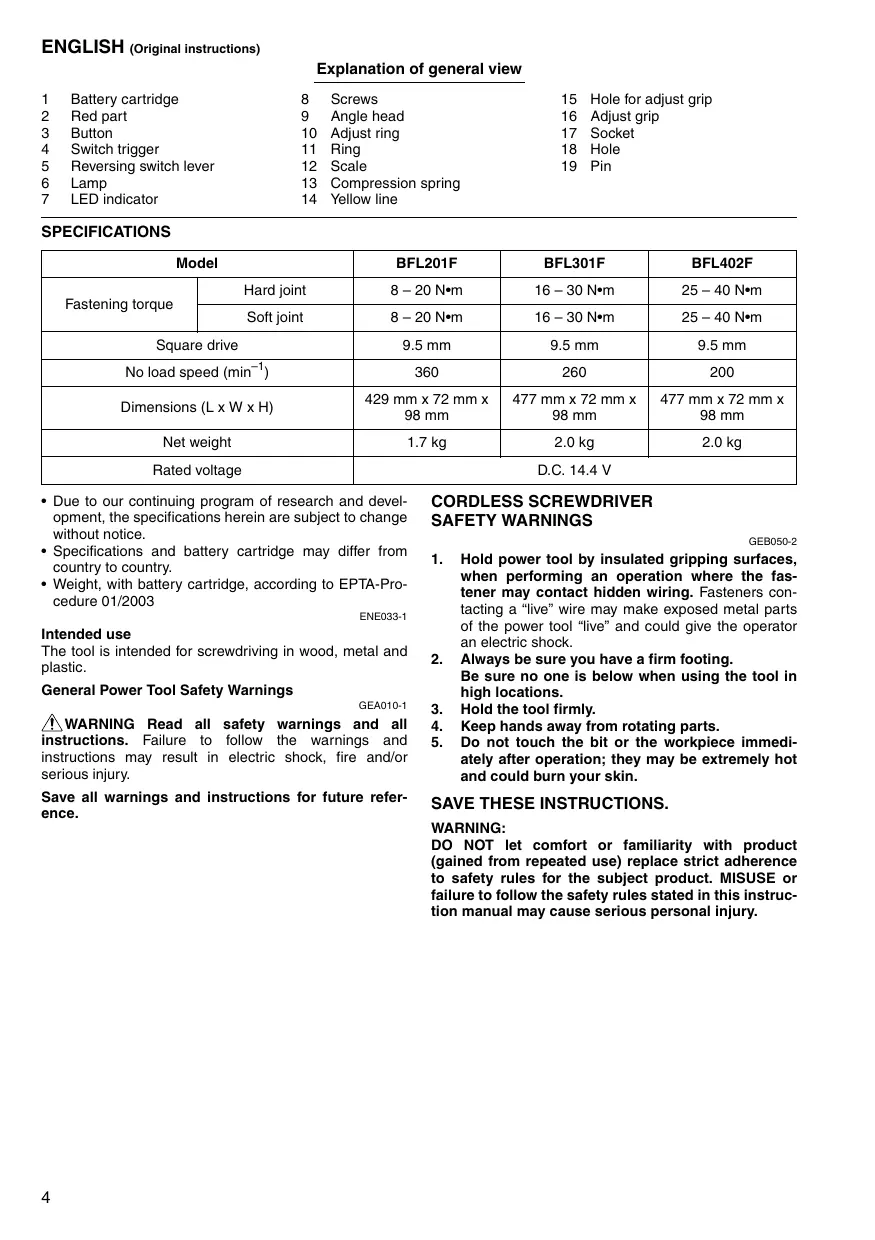
Explanation of general view
SPECIFICATIONS
| 1 | Battery cartridge | 8 | Screws | 15 | Hole for adjust grip |
| 2 | Red part | 9 | Angle head | 16 | Adjust grip |
| 3 | Button | 10 | Adjust ring | 17 | Socket |
| 4 | Switch trigger | 11 | Ring | 18 | Hole |
| 5 | Reversing switch lever | 12 | Scale | 19 | Pin |
| 6 | Lamp | 13 | Compression spring | ||
| 7 | LED indicator | 14 | Yellow line |
| Model | BFL201F | BFL301F | BFL402F | |
| Fastening torque | Hard joint | 8 – 20 N·m | 16 – 30 N·m | 25 – 40 N·m |
| Soft joint | 8 – 20 N·m | 16 – 30 N·m | 25 – 40 N·m | |
| Square drive | 9.5 mm | 9.5 mm | 9.5 mm | |
| No load speed (min-1) | 360 | 260 | 200 | |
| Dimensions (L x W x H) | 429 mm x 72 mm x 98 mm | 477 mm x 72 mm x 98 mm | 477 mm x 72 mm x 98 mm | |
| Net weight | 1.7 kg | 2.0 kg | 2.0 kg | |
| Rated voltage | D.C. 14.4 V | |||
- Due to our continuing program of research and development, the specifications herein are subject to change without notice.
- Specifications and battery cartridge may differ from country to country.
- Weight, with battery cartridge, according to EPTA-Procedure 01/2003
ENE033-1
Intended use
The tool is intended for screwdriving in wood, metal and plastic.
General Power Tool SafetyWarnings
GEA010-1
WARNING Read all safety warnings and all instructions. Failure to follow the warnings and instructions may result in electric shock, fire and/or serious injury.
Save all warnings and instructions for future reference.
CORDLESS SCREWDRIVER SAFETY WARNINGS
GEB050-2
- Hold power tool by insulated gripping surfaces, when performing an operation where the fastener may contact hidden wiring. Fasteners contacting a "live" wire may make exposed metal parts of the power tool "live" and could give the operator an electric shock.
- Always be sure you have a firm footing. Be sure no one is below when using the tool in high locations.
- Hold the tool firmly.
- Keep hands away from rotating parts.
- Do not touch the bit or the workpiece immediately after operation; they may be extremely hot and could burn your skin.
SAVE THESE INSTRUCTIONS.
WARNING:
DO NOT let comfort or familiarity with product (gained from repeated use) replace strict adherence to safety rules for the subject product. MISUSE or failure to follow the safety rules stated in this instruction manual may cause serious personal injury.
IMPORTANT SAFETY INSTRUCTIONS
FOR BATTERY CARTRIDGE
- Before using battery cartridge, read all instructions and cautionary markings on (1) battery charger, (2) battery, and (3) product using battery.
- Do not disassemble battery cartridge.
- If operating time has become excessively shorter, stop operating immediately. It may result in a risk of overheating, possible burns and even an explosion.
- If electrolyte gets into your eyes, rinse them out with clear water and seek medical attention right away. It may result in loss of your eyesight.
- Do not short the battery cartridge:
(1) Do not touch the terminals with any conductive material.
(2) Avoid storing battery cartridge in a container with other metal objects such as nails, coins, etc.
(3) Do not expose battery cartridge to water or rain.
A battery short can cause a large current flow, overheating, possible burns and even a breakdown.
- Do not store the tool and battery cartridge in locations where the temperature may reach or exceed 50^ (122^) .
- Do not incinerate the battery cartridge even if it is severely damaged or is completely worn out. The battery cartridge can explode in a fire.
- Be careful not to drop or strike battery.
- Do not use a damaged battery.
SAVE THESE INSTRUCTIONS.
Tips for maintaining maximum battery life
- Charge the battery cartridge before completely discharged.
Always stop tool operation and charge the battery cartridge when you notice less tool power. - Never recharge a fully charged battery cartridge. Overcharging shortens the battery service life.
- Charge the battery cartridge with room temperature at 10^ - 40^ (50^ - 104^) . Let a hot battery cartridge cool down before charging it.
FUNCTIONAL DESCRIPTION
CAUTION:
Always be sure that the tool is switched off and the battery cartridge is removed before adjusting or checking function on the tool.
Installing or removing battery cartridge (Fig. 1)
- Always switch off the tool before insertion or removal of the battery cartridge.
- To remove the battery cartridge, withdraw it from the tool while sliding the button on the front of the cartridge.
- To insert the battery cartridge, align the tongue on the battery cartridge with the groove in the housing and slip it into place. Always insert it all the way until it locks in place with a little click. If you can see the red part on the upper side of the button, it is not locked completely. Insert it fully until the red part cannot be seen. If not, it may accidentally fall out of the tool, causing injury to you or someone around you.
- Do not use force when inserting the battery cartridge. If the cartridge does not slide in easily, it is not being inserted correctly.
Switch action (Fig. 2)
CAUTION:
- Before inserting the battery cartridge into the tool, always check to see that the switch trigger actuates properly and returns to the "OFF" position when released.
To start the tool, simply pull the switch trigger. Release the switch trigger to stop.
Reversing switch action (Fig. 3)
CAUTION:
- Always check the direction of rotation before operation.
- Use the reversing switch only after the tool comes to a complete stop. Changing the direction of rotation before the tool stops may damage the tool.
- When not operating the tool, always set the reversing switch lever to the neutral position.
This tool has a reversing switch to change the direction of rotation. Depress the reversing switch lever from the A side for clockwise rotation or from the B side for counterclockwise rotation.
When the reversing switch lever is in the neutral position, the switch trigger cannot be pulled.
Lighting up the lamps (Fig. 4)
CAUTION:
- Do not look in the light or see the source of light directly.
Pull the switch trigger to light up the lamp. The lamp keeps on lighting while the switch trigger is being pulled. The light automatically goes out 10 seconds after the switch trigger is released.
NOTE:
- Use a dry cloth to wipe the dirt off the lens of lamp. Be careful not to scratch the lens of lamp, or it may lower the illumination.
LED indicator / Beeper on the tool shows the following functions.
LED indicator / Beeper (Fig. 5)
| Status of the LED indicator/beeper | Function | Status | Action to be taken | |
| LED indicator | Beeper | |||
| Lights up in Green → Red → Blue → White in order. | A series of very short beeps | Check LED, light and beeper (when pulling switch trigger for the first time after installing a battery cartridge into the tool). | Make sure that green, red, blue, white LED lights up and beeper beeps properly. | — |
| Lights up in green for approximately one second. | — | Auto-stop fastening | This function works when the tool has reached the preset fastening torque and normal tightening has been completed. This helps overtightening to be avoided. | — |
| Blinks in purple slowly. | A series of long beeps | Warning for battery cartridge capacity | This indicates the appropriate time to replace the battery cartridge when the battery power becomes low. | Replace the battery with fully charged one. |
| Lights up in purple. | A long beep | Checking the remaining battery capacity, Autostop | This function works when the battery power is almost used up. At this time, tool stops immediately. | Replace the battery with fully charged one. |
| Lights up in red and green alternatively. | A series of short beeps | Anti-reset of controller | This function works when an abnormal drop of the battery voltage occurs for some reason and the tool stops. | Replace the battery with fully charged one. |
| Failure of motor | This function works when motor fails. | Take it to a Makita Authorized Service centers. | ||
| Blinks in red quickly. | A series of short beeps | Overheat | This function works when the temperature of the controller or motor goes up very highly, and the tool stops. | Remove the battery cartridge immediately and cool the tool down. |
| Blinks in red and yellow alternatively. | A long beep | Warning against insufficient fastening | Fastening is incomplete when switch trigger of tool is released before clutch activation. | — |
| Double-hitting detection | This function works when a screw is refastened after fastening. | — | ||
Adjusting the fastening torque
When you wish to drive machine screws, wood screws, hex bolts, etc. with the predetermined torque, adjust the fastening torque as follows.
- First remove the battery cartridge from the tool.
- Loosen and remove the screw that secures ring. (Loosen the two screws that secure ring only for BFL201F) (Fig. 6)
- Rotate the ring in the front of the tool by hand so that a hole can be seen below the ring.
- Place the battery cartridge in place and pull the switch trigger. Release it so that the adjust ring rotates and the hole becomes visible as illustrated (Fig. 7). And then remove the battery cartridge.
- Use an optional adjust grip to adjust the fastening torque. Insert the pin of the adjust grip into the hole in the front of the tool. And then, turn the adjust grip clockwise to set a greater fastening torque, and counterclockwise to set a smaller fastening torque. (Fig. 8)
- Align the edge of the adjust ring with your desired number on the fastening torque scale.
- Insert the battery cartridge and be sure that a fastening torque has been set up by using a fastening torque tester.
- Rotate the ring so that the hole for adjust grip is covered, hold and then secure the ring with screw.
NOTE:
- Numbers on the fastening torque scale is a guideline to set up your desired fastening torque.
ASSEMBLY
CAUTION:
- Always be sure that the tool is switched off and the battery cartridge is removed before carrying out any work on the tool.
Selecting correct socket
There are different types of sockets for some models depending on applications. Choose and install a correct socket for your application.
Installing or removing socket (Fig. 9)
To install the socket, push it onto the square drive of the tool with one hand by depressing a pin on the square drive with another hand until it locks into place. To remove the socket, simply pull it off depressing the pin on the square drive.
OPERATION
Hold the tool firmly and place the socket over the bolt or nut. Then switch the tool on. When the clutch cuts in, the motor will stop automatically. Then release the switch trigger. (Fig. 10)
NOTE:
- Hold the tool with its square drive pointed straight at the bolt or nut, or the bolt or nut will be damaged.
Limits of fastening capacity
Use the tool within the range of the revolution angle up to 360^ . If you use the tool beyond the upper limit of this range, the clutch does not work. And the tool cannot deliver enough fastening torque (LED indicator blinks in purple slowly or lights up in purple).
NOTE:
- The revolution angle means the angle which a screw/ bolt revolves when the tool attains to 100% from 50% of desired torque.
- Use of a low temperature conditioned battery cartridge may sometimes give warning for battery cartridge capacity by warning lamp and beeper which makes the tool stop immediately. In this case, the fastening capacity may be inferior to the specification on this manual even if a charged battery cartridge is used.
MAINTENANCE
CAUTION:
- Always be sure that the tool is switched off and the battery cartridge is removed before attempting to perform inspection or maintenance.
- Never use gasoline, benzine, thinner, alcohol or the like. Discoloration, deformation or cracks may result.
To maintain product SAFETY and RELIABILITY, repairs, any other maintenance or adjustment should be performed by Makita Authorized Service Centres, always using Makita replacement parts.
ACCESSIONS
CAUTION:
- These accessories or attachments are recommended for use with your Makita tool specified in this manual. The use of any other accessories or attachments might present a risk of injury to persons. Only use accessory or attachment for its stated purpose.
If you need any assistance for more details regarding these accessories, ask your local Makita Service Center.
- Makita genuine battery and charger
- Adjust grip
- Protector
Angle head set (For model BFL201F only)
Noise
The typical A-weighted noise level determined according to EN60745:
Model BFL201F, BFL402F
Sound pressure level (L_pA) : 72 dB (A)
Uncertainty (K): 3 dB (A)
The noise level under working may exceed 80 dB (A).
Model BFL301F
Sound pressure level (L_DA) : 74 dB (A)
Uncertainty (K): 3 dB (A)
The noise level under working may exceed 80 dB (A).
Wear ear protection
ENG900-1
Vibration
The vibration total value (tri-axial vector sum) determined according to EN60745:
Work mode: screwdriving without impact
Vibration emission (a_h) : 2.5m / s^2 or less
Uncertainty (K): 1.5m / s^2
ENG901-1
- The declared vibration emission value has been measured in accordance with the standard test method and may be used for comparing one tool with another.
- The declared vibration emission value may also be used in a preliminary assessment of exposure.
WARNING:
- The vibration emission during actual use of the power tool can differ from the declared emission value depending on the ways in which the tool is used.
- Be sure to identify safety measures to protect the operator that are based on an estimation of exposure in the actual conditions of use (taking account of all parts of the operating cycle such as the times when the tool is switched off and when it is running idle in addition to the trigger time).
For European countries only
EC Declaration of Conformity
We Makita Corporation as the responsible manufacturer declare that the following Makita machine(s):
Designation of Machine: Cordless Angle Screwdriver Model No./ Type: BFL201F, BFL301F, BFL402F are of series production and
Conforms to the following European Directives: 2006/42/EC
And are manufactured in accordance with the following standards or standardised documents: EN60745
The technical documentation is kept by our authorized representative in Europe who is:
Makita International Europe Ltd.
Michigan Drive, Tongwell,
Milton Keynes, MK15 8JD, England
26.3.2010

Tomoyasu Kato Director
Makita Corporation
3-11-8, Sumiyoshi-cho,
Anjo, Aichi, JAPAN
Descriptif
1 Batterie
8 Vis
Michigan Drive, Tongwell,
Milton Keynes, MK15 8JD, Angleterre
26.3.2010

Tomoyasu Kato
Director
Makita Corporation
3-11-8, Sumiyoshi-cho,
Anjo, Aichi, JAPAN
Ubersicht
Michigan Drive, Tongwell,
Milton Keynes, MK15 8JD, England
26.3.2010

Tomoyasu Kato Direktor
Makita Corporation
3-11-8, Sumiyoshi-cho,
Anjo, Aichi, JAPAN
Visione generale
Modello BFL201F, BFL402F
Livello pressione sonora (L_pA) : 72 dB (A)
Incertezza (K): 3 dB (A)
Modello No./Tip: BFL201F, BFL301F, BFL402F
Michigan Drive, Tongwell,
Milton Keynes, MK15 8JD, England
26.3.2010

Tomoyasu Kato
Aministratore
Makita Corporation
3-11-8, Sumiyoshi-cho,
Anjo, Aichi, JAPAN
VEILIGHEIDSWAARSCHUWINGEN VOOR ACCU SCHROEVENDRAIAER
GEB050-2
Model BFL201F, BFL402F
Geluidsdrukniveau (L_DA) : 72 dB (A)
Onnauwkeurigheid (K): 3 dB (A)
Modelnr./Type: BFL201F, BFL301F, BFL402F
in sériearend
Michigan Drive, Tongwell,
Milton Keynes, MK15 8JD, England
26.3.2010

Tomoyasu Kato
Director
Makita Corporation
3-11-8, Sumiyoshi-cho,
Anjo, Aichi, JAPAN
Michigan Drive, Tongwell,
Milton Keynes, MK15 8JD, Inglaterra
26.3.2010

Tomoyasu Kato
Director
Makita Corporation
3-11-8, Sumiyoshi-cho,
Anjo, Aichi, JAPAN
Explicação geral
Acender as Iampadas (Fig. 4)
PRECAUÇA:
Michigan Drive, Tongwell,
Milton Keynes, MK15 8JD, Inglaterra
26.3.2010

Tomoyasu Kato
Director
Makita Corporation
3-11-8, Sumiyoshi-cho,
Anjo, Aichi, JAPAN
Model BFL201F, BFL402F
Lydtryksniveau (L_DA) : 72 dB (A)
Usikkerhed (K): 3 dB (A)
Model nr./Type: BFL201F, BFL301F, BFL402F
Michigan Drive, Tongwell,
Milton Keynes, MK15 8JD, England
26.3.2010

Tomoyasu Kato
Direktør
Makita Corporation
3-11-8, Sumiyoshi-cho,
Anjo, Aichi, JAPAN
Iepiypaqni yeviknc aioync
1 Kaoetaa napatias
2 Kokkivo
3 Koumi
4 Szavdaaln diakonntns
5 MoXlo6 8iaKoTTn
avTIOPTpOhC
6 Aaπak
7 Evδειξη LED
8 Biδες
9 i a k k a
10 DaKTuIospuoMuIons
11 a k i o s
12 Kλiμαka
13 Eλatηριο συμπεός
14 Kitpvyn ypaum
15Orn yia npoapuootikn
16 PooaaoostiknlaB
17 YnOdoxn
18 Onn
19 Πειρος
TEXNIKA XAPAKTHPIZTIKA
Michigan Drive, Tongwell,
Milton Keynes, MK15 8JD, England (Ayylambda)
26.3.2010

Tomoyasu Kato
Makita Corporation
3-11-8, Sumiyoshi-cho,
Anjo, Aichi, JAPAN
Makita Corporation
Anjo, Aichi, Japan

- Intended use
- General Power Tool SafetyWarnings
- CORDLESS SCREWDRIVER SAFETY WARNINGS
- SAVE THESE INSTRUCTIONS.
- WARNING:
- IMPORTANT SAFETY INSTRUCTIONS
- FOR BATTERY CARTRIDGE
- Tips for maintaining maximum battery life
- FUNCTIONAL DESCRIPTION
- CAUTION:
- Installing or removing battery cartridge (Fig. 1)
- Switch action (Fig. 2)
- Reversing switch action (Fig. 3)
- Lighting up the lamps (Fig. 4)
- NOTE:
- Adjusting the fastening torque
- ASSEMBLY
- Selecting correct socket
- Installing or removing socket (Fig. 9)
- OPERATION
- Limits of fastening capacity
- MAINTENANCE
- ACCESSIONS
- Noise
- Model BFL201F, BFL402F
- Model BFL301F
- Wear ear protection
- Vibration
- For European countries only
- EC Declaration of Conformity
- We Makita Corporation as the responsible manufacturer declare that the following Makita machine(s):
- Conforms to the following European Directives: 2006/42/EC
- Descriptif
- Ubersicht
- Modello BFL201F, BFL402F
- VEILIGHEIDSWAARSCHUWINGEN VOOR ACCU SCHROEVENDRAIAER
- Acender as Iampadas (Fig. 4)
- PRECAUÇA:
- Iepiypaqni yeviknc aioync
- Makita Corporation
Brand : MAKITA
Model : BFL301F
Category : Power Tools