945GCM5 V2 - Motherboard MSI - Free user manual and instructions
Find the device manual for free 945GCM5 V2 MSI in PDF.

User questions about 945GCM5 V2 MSI
0 question about this device. Answer the ones you know or ask your own.
Ask a new question about this device
Download the instructions for your Motherboard in PDF format for free! Find your manual 945GCM5 V2 - MSI and take your electronic device back in hand. On this page are published all the documents necessary for the use of your device. 945GCM5 V2 by MSI.
USER MANUAL 945GCM5 V2 MSI
FCC-B Radio Frequency Interference Statement
This equipment has been tested and found to comply with the limits for a class B digital device, pursuant to part 15 of the FCC rules. These limits are designed to provide reasonable protection against harmful interference in a residential installation. This equipment generates, uses and can radiate radio frequency energy and, if not installed and used in accordance with the instruction manual, may cause harmful interference to radio communications. However, there is no guarantee that interference will occur in a particular installation. If this equipment does cause harmful interference to radio or television reception, which can be determined by turning the equipment off and on, the user is encouraged to try to correct the interference by one or more of the measures listed below.
n Reorient or relocate the receiving antenna.
n Increase the separation between the equipment and receiver.
n Connect the equipment into an outlet on a circuit different from that to which the receiver is connected.
n Consult the dealer or an experienced radio/ television technician for help.
Notice 1
The changes or modifications not expressly approved by the party responsible for compliance could void the user's authority to operate the equipment.
Notice 2
Shielded interface cables and A.C. power cord, if any, must be used in order to comply with the emission limits.
VOIR LA NOTICE D'INSTALLATION AVANT DE RACCORDER AU RESEAU.

Micro-Star International
MS-7267
Copyright Notice
The material in this document is the intellectual property of MICRO-STAR INTERNATIONAL. We take every care in the preparation of this document, but no guarantee is given as to the correctness of its contents. Our products are under continual improvement and we reserve the right to make changes without notice.
Trademarks
All trademarks are the properties of their respective owners.
AMD® Athlon™ Athlon™ XP, Thoroughbred™ and Duron™ are registered trademarks of AMD® Corporation.
Intel® and Pentium® are registered trademarks of Intel Corporation.
PS/2 and OS®/2 are registered trademarks of International Business Machines Corporation.
Microsoft® is a registered trademark of Microsoft Corporation. Windows® 98/2000/NT/XP are registered trademarks of Microsoft Corporation.
NVIDIA®, the NVIDIA logo, DualNet, and nForce are registered trademarks or trademarks of NVIDIA Corporation in the United States and/or other countries.
Netware® is a registered trademark of Novell, Inc.
Award® is a registered trademark of Phoenix Technologies Ltd.
AMI® is a registered trademark of American Megatrends Inc.
Kensington and MicroSaver are registered trademarks of the Kensington Technology Group.
PCMCIA and CardBus are registered trademarks of the Personal Computer Memory Card International Association.
Revision History
Revision
Revision History
Date
V4.1
Release for 945GCM5 V2 series
April, 2007
(Intel 945GC & ICH7)
Safety Instructions
n Always read the safety instructions carefully.
n Keep this User Manual for future reference.
n Keep this equipment away from humidity.
n Lay this equipment on a reliable flat surface before setting it up.
n The openings on the enclosure are for air convection hence protects the equipment from overheating. Do not cover the openings.
n Make sure the voltage of the power source and adjust properly 110/220V before connecting the equipment to the power inlet.
n Place the power cord such a way that people can not step on it. Do not place anything over the power cord.
n Always Unplug the Power Cord before inserting any add-on card or module.
n All cautions and warnings on the equipment should be noted.
n Never pour any liquid into the opening that could damage or cause electrical shock.
n If any of the following situations arises, get the equipment checked by a service personnel:
- The power cord or plug is damaged.
- Liquid has penetrated into the equipment.
- The equipment has been exposed to moisture.
- The equipment does not work well or you can not get it work according to User Manual.
- The equipment has dropped and damaged.
- The equipment has obvious sign of breakage.
n Do not leave this equipment in an environment unconditioned, storage temperature above 60^ (140^) , it may damage the equipment.
CAUTION: Danger of explosion if battery is incorrectly replaced. Replace only with the same or equivalent type recommended by the manufacturer.

廢電池請回收
For better environmental protection, waste batteries should be collected separately for recycling or special disposal.
WEEE Statement

ENGLISH
To protect the global environment and as an environmentalist, MSI must remind you that...
Under the European Union ("EU") Directive on Waste Electrical and Electronic Equipment, Directive 2002/96/EC, which takes effect on August 13, 2005, products of "electrical and electronic equipment" cannot be discarded as municipal waste anymore and manufacturers of covered electronic equipment will be obligated to take back such products at the end of their useful life. MSI will comply with the product take back requirements at the end of life of MSI-branded products that are sold into the EU. You can return these products to local collection points.
DEUTSCH
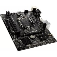
Thank you for choosing the 945GCM5 V2 series (MS-7267 v4.x) Micro-ATX mainboard. The 945GCM5 V2 series are based on Intel® 945GC & Intel® ICH7 chipsets for optimal system efficiency. Designed to fit the advanced Intel® Core2 Duo/ Pentium D/ Pentium 4 / Celeron D processor, the 945GCM5 V2 series delivers a high performance and professional desktop platform solution.
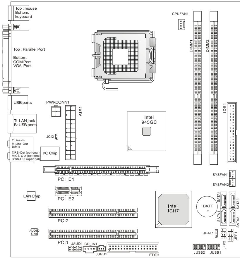
Layout
SPECIFICATIONS
Processor Support
Supports Intel Core2 Duo/ Pentium D/ Pentium 4/ Celeron D LGA 775 processors (For the latest information about CPU, please visit http://global.msi.com.tw/index.php?func=cpuform)
Supported FSB
I 800/533MHz
Chipset
I North Bridge: Intel® 945GC chipset
I South Bridge: Intel® ICH7 chipset
Memory Support
DDR2 400/533/667SDRAM(2GBMax)
1 2 DDR2 DIMMs (240pin/ 1.8V)
(For more information on compatible components, please visit http://global.msi.com.tw/index.php?func=testreport)
LAN
Supports 10/100 Mb/s Fast Ethernet by Realtek RTL 8101E
Or Supports 10/100/1000 Mb/s Fast Ethernet by Realtek RTL 8111B
Audio
Chip integrated by Realtek ALC883, supports HD 5.1-channel audio-out
Or chip integrated by Realtek ALC888, supports HD 7.1-channel audio-out
Vista Premium compliance
IDE
1 IDE port
Supports Ultra DMA 66/100 mode
Supports PIO, Bus Master operation mode
SATA
I 4 SATA ports by ICH7 chipset
Supports 4 SATA devices
Supports storage and data transfers at up to 300 MB/s
Floppy
1 floppy port
Supports 1 FDD with 360KB, 720KB, 1.2MB, 1.44MB and 2.88MB
Connectors
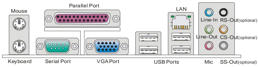
Back panel
- 1 parallel port supporting SPP/EPP/ECP mode
- 1 PS/2 mouse port
- 1 PS/2 keyboard port
- 1 COM port
- 1 VGA port
- 4 USB 2.0 Ports
- 1 LAN jack
- 3 flexible audio jacks (for ALC883 audio chip)
or 6 audio jacks (for ALC888 audio chip)
I On-Board Pinheaders / Connectors
- 2 USB 2.0 pinheaders
- 1 CD-In connector
- 1 Front Panel Audio pinheader
- 1 SPDIF-Out pinheader
- 1 Chassis Intrusion switch pinheader
Slots
1PCIExpressx16slot
1PCIExpressx1slot
I 2 PCI slots (Support 3.3V/5V PCI bus interface)
Form Factor
Micro-ATX (24.5cm X 22.5 cm)
Mounting
1 6 mounting holes
REAR PANEL
The rear panel provides the following connectors:

HARDWARE SETUP
This chapter tells you how to install the CPU, memory modules, and expansion cards, as well as how to setup the jumpers on the mainboard. It also provides the instructions on connecting the peripheral devices, such as the mouse, keyboard, etc. While doing the installation, be careful in holding the components and follow the installation procedures.
CPU & Cooler Installation Procedures for LGA775
When you are installing the CPU, make sure the CPU has a cooler attached on the top to prevent overheating. Meanwhile, do not forget to apply some thermal paste on CPU before installing the heat sink/cooler fan for better heat dispersion.
Follow the steps below to install the CPU & cooler correctly. Wrong installation will cause the damage of your CPU & mainboard.
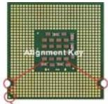
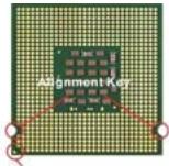
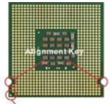
Introduction to LGA 775 CPU
The pin-pad side of LGA 775 CPU.
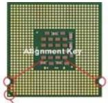
Yellow triangle is the Pin 1 indicator
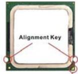
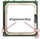
The surface of LGA 775 CPU.
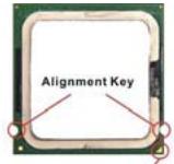
Yellow triangle is the Pin 1 indicator
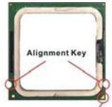
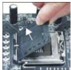
- The CPU socket has a plastic cap on it to protect the contact from damage. Before you have installed the CPU, always cover it to protect the socket pin.
- Remove the cap from lever hinge side.
- The pins of socket reveal.
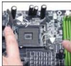
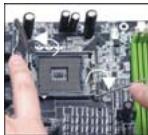
- Open the load lever.
- Lift the load lever up and open the load plate.
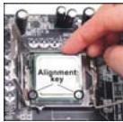
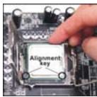
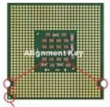
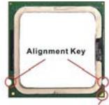
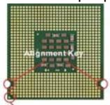
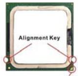
- After confirming the CPU direction for correct mating, put down the CPU in the socket housing frame. Be sure to grasp on the edge of the CPU base. Note that the alignment keys are matched.

- Visually inspect if the CPU is seated well into the socket. If not, take out the CPU with pure vertical motion and reinstall.
- Cover the load plate onto the package.
- Press down the load lever lightly onto the load plate, and then secure the lever with the hook under retention tab.
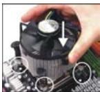
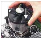
- Align the holes on the mainboard with the cooler. Push down the cooler until its four clips get wedged into the holes of the mainboard.
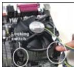
- Press the four hooks down to fasten the cooler. Then rotate the locking switch (refer to the correct direction marked on it) to lock the hooks.
- Turn over the mainboard to confirm that the clip-ends are correctly inserted.
Important:
Read the CPU status in BIOS.
Whenever CPU is not installed, always protect your CPU socket pin with the plastic cap covered to avoid damaging.
Mainboard photos shown in this section are for demonstration of the CPU/ cooler installation only. The appearance of your mainboard may vary depending on the model you purchase.
According to the Intel North Bridge 945GC chipset spec, this board supports CPU of FSB 800MHz at maximum by default. However, you may let your board running at FSB 1066MHz (Core 2 Duo CPUs) by overclocking and adjusting the CPU FSB frequency in the BIOS : Enter BIOS setup menu and go to [Frequency/ Voltage Control]à [Adjust CPU FSB Frequency]. There you can adjust the value to [266] for the Core 2 Duo CPUs. Please be noted that this is over-spec, and this overclocking behavior is not recommended and not guaranteed.
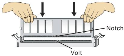
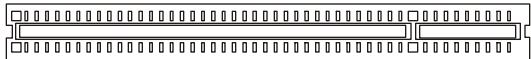
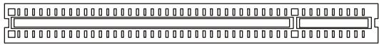
Installing Memory Modules
- The memory module has only one notch on the center and will only fit in the right orientation.
- Insert the memory module vertically into the DIMM slot. Then push it in until the golden finger on the memory module is deeply inserted in the DIMM slot. You can barely see the golden finger if the memory module is properly inserted in the DIMM slot.
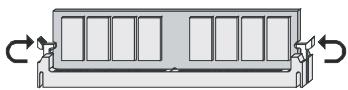
- The plastic clip at each side of the DIMM slot will automatically close.
Important:
DDR2 memory modules are not interchangeable with DDR and the DDR2 standard is not backwards compatible. You should always install DDR2 memory modules in the DDR2 DIMM slots.
To enable successful system boot-up, always insert the memory modules into the DIMM1 first.
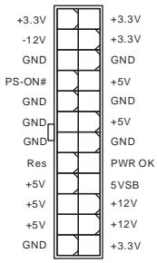
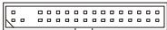
ATX 24-Pin Power Connector: ATX1
This connector allows you to connect an ATX 24-pin power supply. To connect the ATX 24-pin power supply, make sure the plug of the power supply is inserted in the proper orientation and the pins are aligned. Then push down the power supply firmly into the connector.
You may use the 20-pin ATX power supply as you like. If you like to use the 20-pin ATX power supply, please plug your power supply along with pin 1 & pin 13 (refer to the image at the right hand).
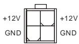
ATX 12V Power Connector: PWRCONN1
This 12V power connector is used to provide power to the CPU.
Important:
Make sure that all the connectors are connected to proper ATX power supplies to ensure stable operation of the mainboard.
Power supply of 350 watts (and above) is highly recommended for system stability.
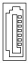
Floppy Disk Drive Connector: FDD1
This connector supports 360KB, 720KB, 1.2MB, 1.44MB or 2.88MB floppy disk drive.
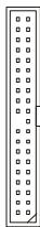
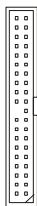
IDE Connector: IDE1
This connector supports IDE hard disk drives, optical disk drives and other IDE devices.
Important:
If you install two IDE devices on the same cable, you must configure the drives to cable select mode or separately to master / slave mode by setting jumpers. Refer to IDE device documentation supplied by the vendors for jumper setting instructions.
Serial ATA Connector: SATA1/2/3/4
This connector is a high-speed Serial ATA interface port. Each connector can connect to one Serial ATA device.
Important:
Please do not fold the Serial ATA cable into 90-degree angle. Otherwise, data loss may occur during transmission.
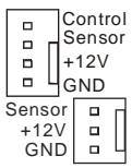
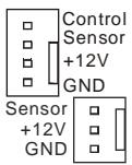
Fan Power Connectors: CPUFAN1, SYSFAN1 & SYSFAN2
The fan power connectors support system cooling fan with +12V . When connecting the wire to the connectors, always note that the red wire is the positive and should be connected to the +12V ; the black wire is Ground and should be connected to GND. If the mainboard has a System Hardware Monitor chipset on-board, you must use a specially designed fan with speed sensor to take advantage of the CPU fan control.
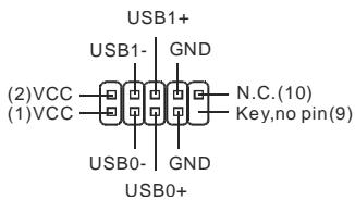
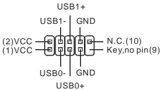
Front USB Connector: JUSB1/ JUSB2
This connector, compliant with Intel® I/O Connectivity Design Guide, is ideal for connecting high-speed USB interface peripherals such as USB HDD, digital cameras, MP3 players, printers, modems and the like.
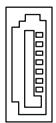
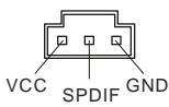
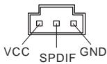
S/PDIF-Out Connector: JSPD1
This connector is used to connect S/PDIF (Sony & Philips Digital Interconnect Format) interface for digital audio transmission.
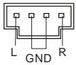
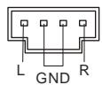
CD-In Connector: CD_IN1
This connector is provided for external audio input.
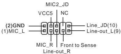
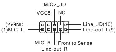
Front Panel Audio Connector: JAUD1
This connector allows you to connect the front panel audio and is compliant with Intel® I/O Connectivity Design Guide.
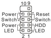
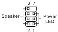
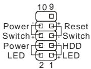
Front Panel Connectors: JFP1, JFP2
These connectors are for electrical connection to the front panel switches and LEDs. The JFP1 is compliant with Intel® Front Panel I/O Connectivity Design Guide.
JFP2
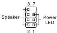
JFP1
Chassis Intrusion Connector: JCI2
This connector connects to the chassis intrusion switch cable. If the chassis is opened, the chassis intrusion mechanism will be activated. The system will record this status and show a warning message on the screen. To clear the warning, you must enter the BIOS utility and clear the record.

Clear CMOS Jumper: JBAT1
There is a CMOS RAM onboard that has a power supply from an external battery to keep the data of system configuration. With the CMOS RAM, the system can automatically boot OS every time it is turned on. If you want to clear the system configuration, set the jumper to clear data.


Important:
You can clear CMOS by shorting 2-3 pin while the system is off. Then return to 1-2 pin position. Avoid clearing the CMOS while the system is on; it will damage the mainboard.
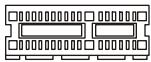
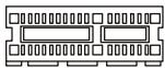
PCI (Peripheral Component Interconnect) Express Slot
The PCI Express slot supports the PCI Express interface expansion card. The PCI Express x 16 supports up to 4.0 GB/s transfer rate.

The PCI Express x 1 supports up to 250 MB/s transfer rate.
PCI (Peripheral Component Interconnect) Slot
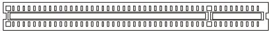
The PCI slot supports LAN card, SCSI card, USB card, and other add-on cards that comply with PCI specifications.
Important:
When adding or removing expansion cards, make sure that you unplug the power supply first. Meanwhile, read the documentation for the expansion card to configure any necessary hardware or software settings for the expansion card, such as jumpers, switches or BIOS configuration.
PCI Interrupt Request Routing
The IRQ, acronym of interrupt request line and pronounced I-R-Q, are hardware lines over which devices can send interrupt signals to the microprocessor. The PCI IRQ pins are typically connected to the PCI bus pins as follows:
| Order1 | Order2 | Order3 | Order4 | |
| PCI Slot1 | INT B# | INT C# | INT D# | INT A# |
| PCI Slot2 | INT C# | INT D# | INT A# | INT B# |
BIOS Setup
Power on the computer and the system will start POST (Power On Self Test) process. When the message below appears on the screen, press key to enter Setup.
Press DEL to enter SETUP
If the message disappears before you respond and you still wish to enter Setup, restart the system by turning it OFF and On or pressing the RESET button. You may also restart the system by simultaneously pressing
Main Page
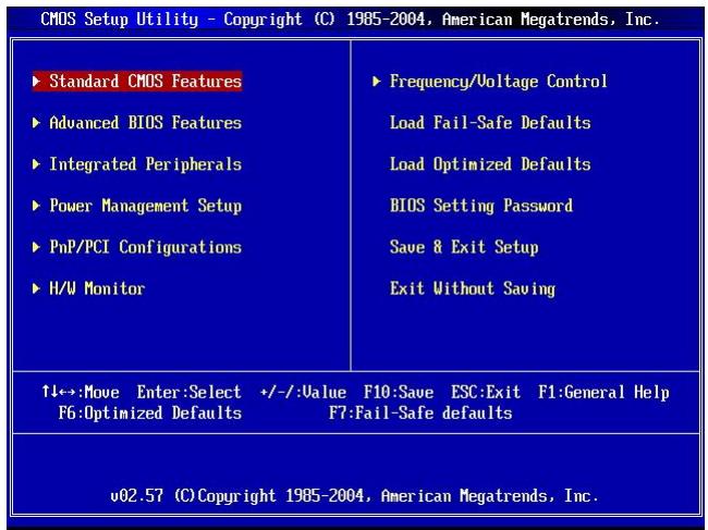
Standard CMOS Features
Use this menu for basic system configurations, such as time, date etc.
Advanced BIOS Features
Use this menu to setup the items of special enhanced features.
Integrated Peripherals
Use this menu to specify your settings for integrated peripherals.
Power Management Setup
Use this menu to specify your settings for power management.
PNP/PCI Configurations
This entry appears if your system supports PnP/PCI.
H/W Monitor
This entry shows the status of your CPU, fan, warning for overall system status.
Frequency/Voltage Control
Use this menu to specify your settings for frequency/voltage control.
Load Fail-Safe Defaults
Use this menu to load the BIOS default values that are factory settings for system operations.
Load Optimized Defaults
Use this menu to load factory default settings into the BIOS for stable system performance operations.
BIOS Setting Password
Use this menu to set BIOS setting Password.
Save & Exit Setup
Save changes to CMOS and exit setup.
Exit Without Saving
Abandon all changes and exit setup.
Frequency/Voltage Control
| CMOS Setup Utility - Copyright (C) 1985-2004, American Megatrends, Inc. Frequency/Voltage Control | ||
| Current CPU Frequency | 3.00GHz (200x15) | Help Item |
| Current DRAM Frequency | 533MHz | FSB600-> Min:200MHz Max:500MHz |
| adjjust CPU FSB Frequency | [200] | Note: When use 667MHz or above 667MHz DDR2 Memory and adjust CPU FSB Frequency above 240, there will be some abnormal status occur sometimes. So it just need to set the item "Configure DRAM Timing by SPD" to "Disabled". It will be OK. |
| adjjust CPU Ratio | [15] | |
| adjjusted CPU Frequency | [3000] | |
| Advance DRAM Configuration | [Press Enter] | |
| FSB/Memory Ratio | [Auto] | |
| Adjusted DDR Memory Frequenc | [533] | |
| adjjust PCI Frequency | [33.33] | |
| adjjust PCIE Frequency | [100] | |
| Auto Disable DIMM/PCI Freque | [Enabled] | |
| Memory Voltage | [1.90] | |
| PCI Express Voltage | [1.55] | |
| Spread Spectrum | [Enabled] | |
| ↑1↔:Move Enter:Select +/-:Value F10:Save ESC:Exit F1:General Help F6:Optimized Defaults F7:Fail-Safe defaults | ||
Current CPU Frequency
It shows the current frequency of CPU. Read-only.
Current DRAM Frequency
It shows the current frequency of Memory. Read-only.
Adjust CPU FSB Frequency
This item allows you to manually adjust the CPU FSB frequency.
Adjust CPU Ratio
This item allows you to adjust the CPU ratio.
Adjusted CPU Frequency
It shows the adjusted CPU frequency (FSB x Ratio). Read-only.
Advance DRAM Configuration > DRAM CAS# Latency
The field controls the CAS latency, which determines the timing delay before DRAM starts a read command after receiving it. [2T] increases system performance while [2.5T] provides more stable system performance. Setting to [By SPD] enables DRAM CAS# Latency automatically to be determined by BIOS based on the configurations on the SPD (Serial Presence Detect) EEPROM on the DRAM module.
FSB/Memory Ratio
This setting controls the ratio of CPU FSB Clock & Memory Frequency to enable the CPU & memory to run at different frequency combinations. Please note that the setting options vary according to the CPU FSB Frequency preset.
Adjusted DDR Memory Frequency
It shows the adjusted DDR Memory frequency. Read-only.
Adjust PCI Frequency
This item allows you to select the PCI clock frequency (in MHz) and overclock by adjusting the PCI clock to a higher frequency.
Adjust PCIE Frequency
This item allows you to select the PCI Express clock frequency (in MHz) and overclock by adjusting the PCI Express clock to a higher frequency.
Auto Disable DIMM/PCI Frequency
When set to [Enabled], the system will remove (turn off) clocks from empty DIMM and PCI slots to minimize the electromagnetic interference (EMI).
Memory/PCI Express Voltage
These items allow you to adjust the Memory/PCI Express voltage. Adjusting the voltage can increase the speed. Any changes made to this setting may cause a stability issue, so changing the voltage for long-term purpose is NOT recommended.
Spread Spectrum
When the motherboard's clock generator pulses, the extreme values (spikes) of the pulses create EMI (Electromagnetic Interference). The Spread Spectrum function reduces the EMI generated by modulating the pulses so that the spikes of the pulses are reduced to flatter curves. If you do not have any EMI problem, leave the setting at Disabled for optimal system stability and performance. But if you are plagued by EMI, set to Enabled for EMI reduction. Remember to disable Spread Spectrum if you are overclocking because even a slight jitter can introduce a temporary boost in clock speed which may just cause your overclocked processor to lock up.
Important:
If you do not have any EMI problem, leave the setting at [Disabled] for optimal system stability and performance. But if you are plagued by EMI, select the value of Spread Spectrum for EMI reduction.
The greater the Spread Spectrum value is, the greater the EMI is reduced, and the system will become less stable. For the most suitable Spread Spectrum value, please consult your local EMI regulation.
Remember to disable Spread Spectrum if you are overclocking because even a slight jitter can introduce a temporary boost in clock speed which may just cause your synchronized processor to lock up.
INTRODUCTION
Yellow triangle is the Pin 1 indicator
Yellow triangle is the Pin 1 indicator

Keep Data
Clear Data
Important:
Slot PCI Express (Peripheral Component Interconnect)
Slot PCI (Peripheral Component Interconnect)
PCI Interrupt Request Routing
Integrated Peripherals
Frequency/Voltage Control
Exit Without Saving :
| CMOS Setup Utility - Copyright (C) 1985-2004, American Megatrends, Inc. Frequency/Voltage Control | ||
| Current CPU Frequency | 3.00GHz (200x15) | Help Item |
| Current DRAM Frequency | 533MHz | FSB800-> Min:200MHz Max:500MHz |
| adjjust CPU FSB Frequency | [200] | Note: When use 667MHz or above 667MHz DDR2 Memory and adjust CPU FSB Frequency above 240, there will be some abnormal status occur sometimes. So it just need to set the item "Configure DRAM Timing by SPD" to "Disabled". It will be OK. |
| adjjust CPU Ratio | [15] | |
| adjjusted CPU Frequency | [3000] | |
| Advance DRAM Configuration | [Press Enter] | |
| FSB/Memory Ratio | [Auto] | |
| Adjusted DDR Memory Frequenc | [533] | |
| adjjust PCI Frequency | [33.33] | |
| adjjust PCIE Frequency | [100] | |
| Auto Disable DIMM/PCI Freque | [Enabled] | |
| Memory Voltage | [1.90] | |
| PCI Express Voltage | [1.55] | |
| Spread Spectrum | [Enabled] | |
| ↑1↔:Move Enter:Select +/-:Value F10:Save ESC:Exit F1:General Help F6:Optimized Defaults F7:Fail-Safe defaults | ||
Current CPU Frequency :
Current DRAM Frequency :
Adjust CPU FSB Frequency :
Adjusted CPU Frequency :
FSB (Front-Side-Bus)
1 800/533MHz
Chipsatz
North-Bridge: Intel® 945GC Chipsatz
Yellow triangle is the Pin 1 indicator
Yellow triangle is the Pin 1 indicator
Frontpanel Anschlüsse: JFP1, JFP2
PCI (Peripheral Component Interconnect) Express Slot
PCI (Peripheral Component Interconnect) Slot
PCI Interrupt Request Routing
Press DEL to enter SETUP
Advanced BIOS Features
Integrated Peripherals
Frequency/Voltage Control
BIOS Setting Password
Frequency/Voltage Control
| CMOS Setup Utility - Copyright (C) 1985-2004, American Megatrends, Inc. Frequency/Voltage Control | ||
| Current CPU Frequency | 3.00GHz (200x15) | Help Item |
| Current DRAM Frequency | 533MHz | FSB600-> Min:200MHz Max:500MHz |
| adjjust CPU FSB Frequency | [200] | Note: When use 667MHz or above 667MHz DDR2 Memory and adjust CPU FSB Frequency above 240, there will be some abnormal status occur sometimes. So it just need to set the item "Configure DRAM Timing by SPD" to "Disabled". It will be OK. |
| adjjust CPU Ratio | [15] | |
| adjjusted CPU Frequency | [3000] | |
| Advance DRAM Configuration | [Press Enter] | |
| FSB/Memory Ratio | [Auto] | |
| Adjusted DDR Memory Frequenc | [533] | |
| adjjust PCI Frequency | [33.33] | |
| adjjust PCIE Frequency | [100] | |
| Auto Disable DIMM/PCI Freque | [Enabled] | |
| Memory Voltage | [1.90] | |
| PCI Express Voltage | [1.55] | |
| Spread Spectrum | [Enabled] | |
| ↑↓↔:Move Enter:Select +/-:Value F6:Optimized Defaults | F10:Save ESC:Exit F1:General Help F7:Fail-Safe defaults | |
Current CPU Frequency
Current DRAM Frequency
Adjust CPU FSB Frequency
Adjusted CPU Frequency
Adjusted DDR Memory Frequency
Adjust PCI Frequency
Adjust PCIE Frequency
Memory/PCI Express Voltage
KOMNOHEHTbI CNTeMHoN INaTbI

XapakTepncnKn
PpOceccop
I PoiDJIeRJiBaIOrTcI npOeCCOpBl Intel Core2 Duo/ Pentium D/ Pentium 4/ Celeron D LGA 775
I Pa3bembl Ha cHCTeMHoN pNaTe
- 2 pa3beMa USB 2.0
- 1 KOHHeTOp CD-In
- 1npot3ByKObIx pa3beMOB nepeHne nane
- 1 SPDIF-Out pa3beM
- 1 pa3bem DaTchka OTKpbBaHnKopnyca
CLOTbl
1PCIExpressx16cnot
1PCIExpressx1cnot
1 2PCI cnoTa (PoiDaepeKka INHTepFeIca 3.3B/5B PCI uINHbI)
ΦopM ΦakTOp
Micro-ATX (24.5cm X 22.5 cm)
KpenJIeHne
6 OTBepCTn IJIa KpenIeHna
3aHЯ paHeJIb
3aHnaHnIb IMeET CJIeDyUOuNe pa3beMbl:
YcTaHOBka 6obOpyIDObaHnIa
3Ta rIaBa nocBraeHa BOpocam yCTaHOBKn pOceccopa, MoJyne nAmrtn, Pnat pacuHpeHna, a TAKKe yCTaHOBKe nepeMbUeK ha CnCTemHoi Pnate. B rIaBe TaKKe paCCKa3bIbaeTcO TOM, KAK NODKNIOUATb BHeUNHe ycTPOINCTBA, TAKNe KaK MbluB, KNAIBNaTpya I.T.I. Prn yCTaHOBKe OobopyoBADHnE ByDte BHNMaTeNbHbI, CNeNyIte YkA3AHNm NO yCTaHOBKe.
UctahOBka npoceccopa LGA 775 n BeHTnJIaTopa
Bo n36eKanHe nepeRpeBa npouecccopa npn erop a6oTe o63aTeNbHo yctaHOBnTe BENTINATOP npouecccopa. He 3a6yIbTe HaheCTn TepNoPBOOJaUyIO NaCTy Ha BepxNHO KpbIuKy npouecccopa neped yctaHOBKO paHaTOpA/ BENTINATOP npouecccopa. HnKe pIeDCTaBLeHbI yka3aHnI NO npabUnbHOY uCTaHOBKe npouecccopa N BENTInJrTopa. HnpabunbHaay cTaHOBKa MoKET npnbEcTn K nobpeXdeHIO npouecccopa nCnCTEmHO nnAtbl.
YctaHOBka npoueccopa LGA 775
BvI npoueesscopa co cToPOHbI KOHTaKTHOI naHeJI LGA 775.
Yellow triangle is the Pin 1 indicator
BHeuHn BvD npOceccopa LGA 775.
Yellow triangle is the Pin 1 indicator
- Pa3bem npoceccopa 3akpbIIT nlaactNKOBO KpbIshKO, KOtopra 3aunuaeT KOHTaKTBp3beMa OT NOBpeXdEHn IN 3arpy3HeHNI. EcIn npoceccop He yCTaHOBJIeB pa3bem, Heo6xOJIMO Bcerda 3akpbIBaTB erO nlaactNKOBO KpbIshKO INIy 3aunTbOT NblIN N NOBpeXdEHN.
- Chmnte KpbIuKy, noHBe ee c OdHoi CTOpOHyI.
- OtkpoHOTcKoHTaKTbI pa3beMa.
4.Подимпerte pybuar noTkoPte pa3beMдя yctaHOBKn
npoceccopa.
- Y6eINBnCb B npaBnBHOI opNEtauN INPOCEcoppa, nIOXnTe IPOeCCOP B pa3bEm. O6paTnTe BnIMaHne, yTO BbIEMKn Ha IPOeCCope DoJNXbI COOTBeTCTBOBaTb BbICTyNam Ha IPOeCCOPHom pa3bEme.
- Поберпглбьсь усановки поцessорв раьem Bn3yaJIbHo. Ecп поцesscop усановпн HeрразиьHo,TO BBHbTe поцessop И nepeyctaHOBITE.
- Onyctnte MeTaIInuYeckyU KpbIiKU MexaHn3Ma KpeIJIeHna.
- AkkypaTHO onyCTnTe pbUar Ha KpbIuKу MexaHn3Ma KpeJIeHnI N 3aФнICuPnyTe erO. ДЯ SFKcaUN pIbYar a B MExaHn3Me KpeJIeHnI PpeDyCmTpeMJIeHbKIN KpIouOK.
- CoBmecntte OTBepCTnI CNTeMHoI IaTbI c 3aueIkamn KpeIeHnBEHTNlAToPAp.IpnKMTe paIaNtOp C BeHTNlAToPOM K pOuEccopy u IpocSeIeIte, YTObI yTeblpe 3aUeJIKN BOUIN B OTBepCTnI CNTeMHoI IaTbI.
- Haxmnte Ha Yetbipe 3auejkn n 3akpenTe BENTnIaTOp. 3aTe m nobepHnTe fKcAtopbl 3aueJok (Ha npabJeHne nOBopoTa yka3aHo Ha BENTnIaTope) n 3akpenTe nx.
- Пелевернite системную плату и убадитесь, что зашикни дожно удахимbaю BeHTINЯТOP.

BhimaHne:
CocToHHe npOeCCopa cMoTpne B paZdJeBIOS.
Ecni npocecop He yctaHOBneH, BcERda 3akpbBaIte pa3bEm pIaCTNKOBoK kpbIkwOДпЯ npedotBpauSeHn nonOMOK nnonaDaHn B Hero rpr3n nblJN.
ФOTOCNCTeMHOHПаТь,pa3MeUeHHbIeB3ToIyactN,PnIBeHbTOnbKOДЯDEMOHCTpauuYCTaHOBKnBeHTnIpyTopa.ObuINBIDCNCTeMHOHПaTbI3aBNCITOTMоДЛ,КуПLEHHO BAMN.
EcnBbI NOKJIIOUaTe DBA yCTpoiCTBa K OJHOmy Ka6eHIO IDE, BTOPOe DOnXHo 6bITb yCTaHOblnEO H pexIM "Slave" nepeKJIIOuATenEM Ha yCTpoiCTBe. ObpaNTIEcB K pa3dny, nocBraJeHHOMy yCTaHOBKe
nepeKIOUOaTeIeN, B DOkUMeHTaIeN, NOCTaBJIeMoI npOn3BOJNTeIeM OobpyUDoBaHn.
Pa3bembl Serial ATA: SATA1/2/3/4
Pa3bem SATA - 3TO BbICOKOCKOPoCTHOI NOP INHTeppeca Serial ATA.
3TOT pa3bem MOXeT NOcOeINHrTB ONo H yCTpoIcTBo Serial ATA.
BhimaHne:
I36eaiTe pe3kux n3rnoB KBa6en Serial ATA. B npotnBHom cnyae MoryT BO3HNKHyTb NOTepu DaHHbIX npi nepeJaue.
Pa3bEmblI\PHTaHnBBeHTnJIaTOpOB:CPUFAN1, SYSFAN1u SYSFAN2
Pa3bEmbl nITaHnBEHTnIaTOpOB NOdepKINBaOT BeHTnIaTOpbl c nITaHnEM +12B. Ppi NpOKJIoueHn HcO6xOJMo NOMHTb, YTO KpaCHbI npOBoN pOKJIouaetcK 5uHne +12B, a cepHbI -K 3emIe GND. EcInn CnCTeMHra PIIaTc COePjNT MKNPOCxEMy aannapatHO rO MOHTOpHNrA, Heo6XoJIMo IcONb30BaTb CneuaJIbHbIe BEHTnIaTOpbl C DaTChKOM CKOPoCTn Dlra peaNN3aunФyHKUn ynpabNeHn BeHTnIaTOpOM.
Pa3bem USB nepeDnei paHeJN: JUSB1/JUSB2
Pazbem COOTBETCTBYET TexHONorN Intel I/O
Connectivity Design Guide, KOTOPA nIealbHa IINn PNOKIOUeHn TAKNX BbICOKOCOPoCTbIX yCTPOICTB KaK USB HDD, UNPPOBbIX KaMEp, MP3 nIpeepo, npINTepOB, MoEMOB nT.D.
Pa3bem BbIXoJa S/PDIF: JSPD1
Pa3bem n03B0JraT NOdKJIIOUHTb 3ByKOBbIe pa3bembl nepeDneH naHenn. OH COOTBeTcTByET cneuФиKaunn Intel I/O Connectivity Design Guide.
Pa3bEmbl opraHOB ynpaBJIeHnI INHdNKaTOPOB nepeDHeN paHeJI: JFP1, JFP2
3Tn pa3bembl obecneuHBAUOT nOdklnouHe nOpraHOB ynpablenna INndkaTOpOB nepeDnei naHEn. JFP1 cooTBetCTByET cneuΦkaunl Intel®Front Panel I/O Connectivity Design Guide.
JFP2
JFP1

Pa3beMbI PCI Express (Peripheral Component Interconnect)
PCI Express cnot noDepKnBaET dONOHNTeHbIe KapTbI paCUnpeHna INTEppeCa PCI Express.
PCI Express x 16 cnot noideperxmbaet ckopoctb nepeadau do 4.0 GB/c

PCI Express x 1 cnot noidepkxnbae ckopocb nepeaun do 250 MEC.
Pa3beM PCI (Peripheral Component Interconnect)

Pa3bemPCI no3BONrE yCTaHaBnBaTb KapTy LAN, SCSI, USB n npyrne DOnonHnTeNbHbe KApTbI paCunpeHn, KOtOpbIe COOTBeTcByIOT xapakTepcntkam PCI.
BHMaHne:
Ipepe yctahOBKO nnnn 3BneHem KapTbI paCunpeHn y6eNTecb, YTO Ka6enbl nntAHnO kNtoueh OT 3NeKtpnuecko cetn. IpoTuTe DOKyMeHTaUNo Ha KapTy paCUnpeHn N BbInONHnTe Heo6XoDmblte aNNapatHbIe nnPi npOrpamMhIbe yCTaHOBKn dJaDaHNO pNaTbI (pepeMbUKN, nepeKlnuOATEEN nn KOnΦnrgpaunia BIOS).
Advanced BIOS Features
IcnoJIb3yETcI JnHAcTPOKIN DOnOJIHHTeNbHbIX BO3MOXHOCTe CNTeMbI.
Integrated Peripherals
IcnoIb3yETcIaHacTpoKn npaMeTPOB BCTpoEHHbIX nepuΦepriNbIX yCTpoICTB.
Power Management Setup
IcnoIb3yETcI dI NaHCTpoKn npaMeTPOB 3HePrc6peKeHIn.
PNP/PCI Configurations
IcnoIb3yeTcA InHacTpoKn CnCTeMbI, nOndePknBaIOe yCtpoCTBa PnP/PCI.
H/W Monitor
IcnoJIb3yETcI JIIMMOHITOpINHa CNTeMbI.
Frequency/Voltage Control
IcnoB3yETcIy yCTaHOBKn YactOTbI HnapJxehna.
Load Fail-Safe Defaults
IcnoIb3yeTc npn 3aRpy3Ke 3NaueHnBIOS,yCTaHOBHeHbIe npOn3BOUInTeIeM o6OpyOboAHnI dIg CtaBnJIbHO pa60tbl cNCTeMbI.
Load Optimized Defaults
Icnonbayetc npn 3arpy3ke 3nauehenBIOS'a dnn paobToC onTImaJIbHOI npOn3BOUntelbHocThbIO.
BIOS Setting Password
IcnoB3yETc dIy yCTaHOBKn npOJIa.
Save & Exit Setup
IcnoB3yeTcra IJI BbIXOJa I3 MeHIO yCTaHOBKn C COXpaHeHnEM BHeceHHbIX I3MeHeHn (CMOS).
Exit Without Saving
IcnoIb3yETcA JIe BixOda I3 MeHIO yCTaHOBKn C NOTEpei BCEX BHeCEHHbIX I3MeHeHn.
Frequency/Voltage Control (Уни вени частотамн/напяжения)
| CMOS Setup Utility - Copyright (C) 1985-2004, American Megatrends, Inc. | ||
| Frequency/Voltage Control | ||
| Current CPU Frequency | 3.00GHz (200x15) | Help Item |
| Current DDRAM Frequency | 533MHz | FSB300-> Min:200Mhz Max:500Mhz |
| Adjust CPU FSB Frequency | [200] | Note: When use 667MHz or above 667MHz DDR2 Memory and adjust CPU FSB Frequency above 240, there will be some abnormal status occur sometimes. So it just need to set the item "Configure DDRAM Timing by SPD" to "Disabled". It will be OK. |
| Adjust CPU Ratio | [15] | |
| Adjusted CPU Frequency | [3000] | |
| Advance DDRAM Configuration | [Press Enter] | |
| FSB/Memory Ratio | [Auto] | |
| Adjusted DDR Memory Frequenc | [533] | |
| Adjust PCI Frequency | [33.33] | |
| Adjust PCIE Frequency | [100] | |
| Auto Disable DIMM/PCI Freque | [Enabled] | |
| Memory Voltage | [1.90] | |
| PCI Express Voltage | [1.55] | |
| Spread Spectrum | [Enabled] | |
| TJ←:Move Enter:Select +/-:Value F10:Saue ESC:Exit F1:General Help F6:Optimized Defaults F7:Fail-Safe defaults | ||
Current CPU Frequency
3TOT nyHKT nOKa3bIbAe TEkyUee 3HaHeHne TaKTOBO YacTObI npoceccopa.
Current DRAM Frequency
3TOT NYHK T NOKa3bIaBETekUe 3HaueHne TaKTOBOn YaCTOTbI NaMRTN.
Adjust CPU FSB Frequency
3TOT nyHKT no3B0JraET BpyHyIO peryIINPOBaTb yactoty FSB npoceccopa.
Adjust CPU Ratio
3TOT nyHKT no3BONaRET peryIINPOBaTB KO3ΦΦuIeHT yMHOKeHn IpoUeCCopa.
Adjusted CPU Frequency
3TOT nyHKT NOKa3bIbaET YacToTy npoueccopa (FSB x Ratio).
Advance DRAM Configuration > DRAM CAS# Latency
3TOT nyHKT KOHTPOINPYET latENTHOCTB CAS, KOTOPA n3MepaET BpeMeHHyO 3aedKky DRAM npu YteHn DaHHbIX. 3HaueHne [2T] ynyuINT npo3BOIDTeHBOCTB cNCTeMbI, a 3HaueHne [2.5T] o6ceHuBaet 60one CtaBnHyIO pa6O TY cNCTeMbI. 3aaiTe 3HaueHne [By SPD], YTO6bl YcTAHOBnTB BpeMeHHbIe npaMeTpbl DRAM CAS# Latency abTomatUeCKn B COOTBeTCTBn C daHHbIMN SPD (Serial Presence Detect) EEPROM ha MoDyne DRAM.
FSB/Memory Ratio
TOT nyHKT no3B0JraET BpyHyu peyHnpoBaTa OTHoUeHne YactOtbl FSB/Ratio namrtn.
Adjusted DDR Memory Frequency
3TOT NyHKT NOKa3bIbae T acToTy namrT DDR.
Adjust PCI Frequency
3TOT nyHKT nO3BONJrET BbIbpaTb TeKUe 3HaueHne yAcToTbPCI (Mf) n npOn3BeCTn pa3ROH CnCTemblnyTEM yBEnuHern 3HaueHn yAcToTbPCI.
Adjust PCIE Frequency
3TOT nyHKT nO3BONJraET bIbpaTaB Tekyuee 3NaueHne 3aueHne 3aueHne 3aueHne 3aueHne 3aueHne 3aueHne 3aueHne 3aueHne 3aueHne 3aueHne 3aueHne 3aueHne 3aueHne 3aueHne 3aueHne 3aueHne 3aueHne
Auto Disable DIMM/PCI Frequency
Пиу установке 3наченя [Enabled] (pa3peшeo) систema abTomatческг OTКЛЮЧТ HeINСПОЛьзУЕмBLE pa3bemblamЯтNi pa3bemblPCI,чTO ппвetedд К chнжehию уровьг 3л ekтоматнIHbIXnomex(EMI).
Memory/PCI Express Voltage
3TOT nyHKT npedHa3nauHdIy HacToPoiKn HapJxHeHMy MoUyni NaMrtu /PCI Express, yTO nO3BOJAREYBeJIuNcBaTb INCKOpocTb. IIO6bIe N3MeHEnHr 3TOrO nyHKTa MOryt npINBecTI K CHNXeHIno CTaBnIbHOCTn, I03TOMy He peKOMeHdyETcR N3MeHrTb HApJxKeHne NIITAHNl NaMAtn Ha dIITeJIbHoE BpEmr.
Spread Spectrum
Tak KaT KobI rHepeaTOp CnCTeMHoN pIaTbIMnYnbChbI, To erO pa6Ota Bbl3bIbaET 3NeKtpomarHHTbIe nomexi - EMI (Electromagnetic Interference).ФункцЯ Spread Spectrum cHxkaeT3n NOMEXn, rHeepnyrCrraxeHbIe IMnYnbCSbI. EcIy y Bac HET np6bIem C nOMexAmOCTabTe 3NaueHene [Disabled] (3anpeseHo) dIra Iyuwei CTaBnHbOcTN iPOn3BODnteJIbHOCTN. Ondako, ecIn y Bac Bo3HnKaIOT 3neKtpomarHHTbIe nomExn, pAspeWte NcNoNtB3OBAHne 3ToI FyHKzU, yCTaHOVB [Enable] (pa3peSeHo). He 3a6yDte 3AnpTeNTb NcNoNtB3OBAHne FyHKzMn Spread Spectrum, ecIn Bbl «pa3roHareTe" CnCTeMHyIO pNAty. 3To Heo6XoDMo, Tak KaJ daKe He6oBlsWo dpe6e3r CnHAnOB TAKTOBO rHeepaTOP MoKet npVBeCTN K OTKa3y «Pa30HaHHoro» npOceccopa.
BhimaHne:
EcIn y Bac HET npo6nem C nomexamn, ocTaBbTe 3naueHne [Disabled] (3anpeuho) nlaJyUeW CTaBnIbHOCTn IN pOn3BOAnITeBbHOCTn. Ondako, ecIn y Bac Bo3NkaIoT 3JIeKTPomarHHThIE nomExn, Bbl6epnte Spread Spectrum dIra nx yMeHbSeHnA.
1个floppy端口
支持1个360KB,720KB,1.2MB,1.44MB和2.88MB FDD
接口
后置面板
LG775 CPU的针脚面
Yellow triangle is the Pin 1 indicator
LG775 CPU 的表面.
Yellow triangle is the Pin 1 indicator

Keep Data
Clear Data
注意:
Press DEL to enter SETUP
Integrated Peripherals (整合周边)
使用此菜单可对周边设备进行特别的设定。
Adjust CPU FSB Frequency (调整CPUFSB频率)
Adjusted CPU Frequency (调整CPU频率)
Press DEL to enter SETUP
Integrated Peripherals (整合型週邊)
使用本選單設定整合型週邊裝置。
Adjust PCIE Frequency (PCIE 频率)
LGA 775 CPUのpin-pad側
Yellow triangle is the Pin 1 indicator
LGA 775 CPUの正面
Yellow triangle is the Pin 1 indicator
Press DEL to enter SETUP
Advanced BIOS Features
SntUsの特別機能の設定を行いま�。
Integrated Peripherals
Frequency/Voltage Control
BIOS Setting Password
八スフ一卜を設定しま�。
Save & Exit Setup
Frequency/Voltage Control
| CMOS Setup Utility - Copyright (C) 1985-2004, American Megatrends, Inc. | ||
| Frequency/Voltage Control | ||
| Current CPU Frequency | 3.00GHz (200x15) | Help Item |
| Current DRAM Frequency | 533MHz | FSB800-> Min:200Mhz Max:500Mhz |
| Adjust CPU FSB Frequency | [200] | |
| Adjust CPU Ratio | [15] | |
| Adjusted CPU Frequency | [3000] | |
| Advance DRAM Configuration | [Press Enter] | |
| FSB/Memory Ratio | [Auto] | |
| Adjusted DDR Memory Frequenc | [533] | |
| adjjust PCI Frequency | [33.33] | |
| adjjust PCIE Frequency | [100] | |
| Auto Disable DIMM/PCI Freque | [Enabled] | |
| Memory Voltage | [1.90] | |
| PCI Express Voltage | [1.55] | |
| Spread Spectrum | [Enabled] | |
| 11↔:Move Enter:Select +/-:Value F10:Save ESC:Exit F1:General Help F7:Fail-Safe defaults | ||