
PMA-495R - Audio Amplifier DENON - Free user manual and instructions
Find the device manual for free PMA-495R DENON in PDF.
| Product type | Stereo integrated amplifier |
| Brand | DENON |
| Model | PMA-495R |
| Audio inputs | PHONO (MM), CD, TUNER, AUX, TAPE-1/CD-R, TAPE-2/MD |
| Audio outputs | Speakers A and B (screw terminals), 6.35 mm headphone jack |
| Speaker switching | Selection A, B or A+B, deactivation for headphones |
| Source direct | Yes (bypass balance, tone, loudness) |
| Tone controls | Bass (BASS) and treble (TREBLE), flat center settings |
| Loudness compensation | Variable (LOUDNESS) for low volume listening |
| Balance | Left/right balance adjustment |
| Remote control supplied | RC-176, infrared, range 8 m |
| Remote control batteries | 2 x R6P (AA) |
| Remote control functions | Control amplifier, CD player, cassette deck, DENON tuner |
| Protection circuit | Fast short-circuit protection |
| Ventilation | Free space of at least 10 cm above and around |
| Power supply | Mains (230 V / 50 Hz, estimate) |
| Included accessories | Remote control RC-176, 2xAA batteries, instruction manual, service center list |
| Cassette copy function | From TAPE-1/CD-R to TAPE-2/MD |
| Standby mode | Via remote control, MUTE/STANDBY indicator lit |
| Power-on delay | A few seconds (muting circuit) |
Frequently Asked Questions - PMA-495R DENON
User questions about PMA-495R DENON
0 question about this device. Answer the ones you know or ask your own.
Ask a new question about this device
Download the instructions for your Audio Amplifier in PDF format for free! Find your manual PMA-495R - DENON and take your electronic device back in hand. On this page are published all the documents necessary for the use of your device. PMA-495R by DENON.
USER MANUAL PMA-495R DENON
INTEGRATED STEREO AMPLIFIER
PMA-495R
OPERATING INSTRUCTIONS
TO PREVENT FIRE OR SHOCK HAZARD, DO NOT EXPOSE THIS APPLIANCE TO RAIN OR MOISTURE.
"SERIAL NO.
PLEASE RECORD UNIT SERIAL NUMBER ATTACHED TO THE REAR OF THE CABINET FOR FUTURE REFERENCE"
CAUTION:
- The ventilation should not be impeded by covering the ventilation openings with items, such as newspapers, tablecloths, curtains, etc.
- No naked flame sources, such as lighted candles, should be placed on the apparatus.
- Please be care the environmental aspects of battery disposal.
- The apparatus shall not be exposed to dripping or splashing for use.
- No objects filled with liquids, such as vases, shall be placed on the apparatus.

CAUTION RISK OF ELECTRIC SHOCK DO NOT OPEN

CAUTION: TO REDUCE THE RISK OF ELECTRIC SHOCK, DO NOT REMOVE COVER (OR BACK). NO USER-SERVICEABLE PARTS INSIDE. REFER SERVICING TO QUALIFIED SERVICE PERSONNEL.

The lightning flash with arrowhead symbol, within an equilateral triangle, is intended to alert the user to the presence of uninsulated "dangerous voltage" within the product's enclosure that may be of sufficient magnitude to constitute a risk of electric shock to persons.

The exclamation point within an equilateral triangle is intended to alert the user to the presence of important operating and maintenance (servicing) instructions in the literature accompanying the appliance.
- DECLARATION OF CONFORMITY
We declare under our sole responsibility that this product, to which this declaration relates, is in conformity with the following standards:
EN60065, EN55013, EN55020, EN61000-3-2 and EN61000-3-3.
Following the provisions of 73/23/EEC, 89/336/EEC and 93/68/EEC Directive.
For heat dispersal, leave at least 10cm of space between the top, back and sides of this unit and the wall or other components.
Please check to make sure the following items are included with the main unit in the carton:
(1) Operating Instructions 1
(2) Remote Control Unit (RC-176) 1
(3) Batteries R6P (AA) 2
(4) Service Station List 1
- Always keep the POWER switch on the main unit turned on.
- Turn the power on and off from the remote control unit.
- Unplug the power supply cord when you do not plan to use the unit for a long period of time.
CAUTION:
If only the MUTE/STANDBY LED is lit, this means that the power is turned off from the remote control unit. Turn the power on from the remote control unit.
HINWEIS:
Allow for sufficient heat dispersion when installed on a rack.
- Handle the power cord carefully.
Hold the plug when unplugging the cord.
* (For sets with ventilation holes)
- Do not obstruct the ventilation holes.
Die Belüftungsöffnungen können nicht verdeckt werden. - Ne pas obstruer les trouss d'airation.
Non coprite i fori di ventilazione. - No obstruya los orificios de ventilación.
- De ventilatieopengen mogen nicht worden beblokkeerd.
Tappinte tillventilationsoppningarna. - Não obtrua os orificios de ventilação.
- Do not let foreign objects in the set.
- Keine fremden Gegenstände in das Gerätkommen halten.
- Ne pas laisser des objets étrangers dans l'appareil.
- E' importante che Nessun oggetto è inserto all'interno dell'unità.
- NoADEjebotontrasnoidtrodelequipo.
- Laat geen vreemde voorwerpen in dit apparaat vallen.
- Se till att främande foremål inte tränger in i apparaten.
- São deixe objetivos estranhos no aparelho.

- Do not let insecticides, benzene, and thinner come in contact with the set.
- Lassen Sie das Gerät nicht mit Insektiziden, Benzin oder Verdünningsmitteln in Berührung kommt.
- Ne pasmettre en contact des insecticides,du benzene et un diluant avec I'appareil.
- Assicuratevvi che l'unità non venga in contatto con insetticidi, benzolo o solventi.
- No permitted contacto de insecticidas, gasolina y diluyentes con el equipo.
- Laat geen insetkenverdelgende middelen, benzine of verfverdunner met dit apparaat in contactumen.
- Se till att inte insetktsmedel på spraybruk, bensen och thinnerkommen i kontakt med apparatens höje.
- Não permita que insetucidas, benzina e dissolvente entrem em contacto com o aparelho.

- Never disassemble or modify the set in any way.
Versuchen Sie niemals das Gerät auseinander zunehmen oder auf jegliche Art zu verändern. - Ne jamais démonter ou modifier l'appareil d'une manière ou d'une autre.
Non smontate mai, nè modificate l'unità in nessun modo. - Nunca desarme o modifique el equipo de ninguna manera.
- Nooit dit apparaat demonteren of op andere wijze modifierten.
- Ta inte isär apparaten och försök inte bygga om den.
- Nunca desmonte ou modifique o aparelho de alguma forma.
FRONT PANEL
FRONTPLATTE
PANNEAU AVANT
PANNELLO ANTERIORE
REAR PANEL
RUCKWAND
PANNEAU ARRIERE
PANNELLO POSTERIORE
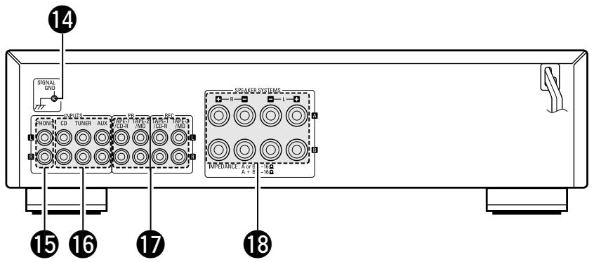
Fig. 1
Abb.1
| 14 SIGNAL GND | 15 PHONO | 16 CD, TUNER, AUX | 17 TAPE-1/CD-R, TAPE-2/MD • TAPE PB • TAPE REC | 18 SPEAKERS |
| GND | Phono Input Terminals (Phono) | Input Terminals (CD, TUNER, AUX) | Playback and Recording Terminals • Playback Terminals • Recording Terminals | Speaker Terminals |
| GND | Schallplattenspieler-Eingangsbuchsen (Phono) | Eingangsbuchsen (CD, TUNER, AUX) | Tonband-Ein/Ausgänge • Wiedergabe • Aufnahme | Lautsprecher-klemmen |
| GND | Bornes d'entrée (phono) | Bornes d'entrée (CD, TUNER, AUX) | Bornes de lecture et d'enregistrement • Bornes de lecture • Bornes d'enregistrement | Bornes de haut-parleurs |
| GND | Terminali di ingresso Phono | Terminali di ingresso (CD, TUNER, AUX) | Terminali di riproduzione registrazione • Terminali di riproduzione • Terminali di registrazione | Terminali degli altoparlanti |
PANEL FRONTAL
VOORPANEEL
FRAMSIDA
PAINEL FRONTAL

PANEL TRASERO
ACHTERPANEL
BAKSIDA
PAINEL TRAZEIRO
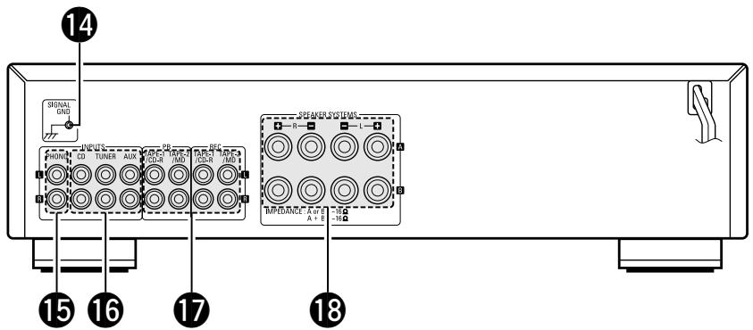
Fig. 1
Afb. 1
| 14 SIGNAL GND | 15 PHONO | 16 CD, TUNER, AUX | 17 TAPE-1/CD-R, TAPE-2/MD • TAPE PB • TAPE REC | 18 SPEAKERS |
| GND Terminal de toma | Terminales de entrada de Phono | Terminales de reprodução y grabación (CD, TUNER, AUX) | Terminales de reproducción y grabación • Terminales de reproducción • Terminales de grabación | Terminales de altavoces |
| GND A Harding | Draaitafelingangs-aansluitpunten | Ingangsaansluitpunten (CD, TUNER, AUX) | Weergave- en opname-aansluitpunten • Weergave-aansluitpunten • Opname-aansluitpunten | Luidspreker-aansluitpunten |
| GND | Skivspelaringångar | Ingångar (CD, TUNER, AUX) | Bandansluttingar • Avspelningsansluttingar • Inspelningsansluttingar | Högtalarkontakter |
| GND | Terminais de entrada de fono (Fono) | Terminais de entrada (disco compacto, sintonizador, auxílio) (CD, TUNER, AUX) | Terminais de reprodução e gravação • Terminais de reprodução • Terminais de gravação | Terminais de alto-falante |
CONNECTIONS
ANSCHLUSSE
CONNEXIONS CONNECTIONI
Tape deck or MD recorder
Cassetten-Deck oder MD-Bekorder
Platine cassette ou MD
Piastra del registrar o registrarato MD
Tape deck or CD recorder
Cassetten-Deck oder CD-Rekorder
Platine cassette ou enregistrur de CD
Piastra del registratore o registratore CD
Ground Wire
* Connect the ground wire,
but disconnect it if
humming or other noise
is generated
rdungskabel
- Schließen Sie die
Erdungsleitung an.
Connection to the Speaker System
- Peel off the sheathing from the end
of the cord. - Twist the wire strands
-
Loosen the speaker terminal, insert the wire lead portion of the code, and then tighten the terminal.
-
Ein Stück der Isolierung am Kabelende
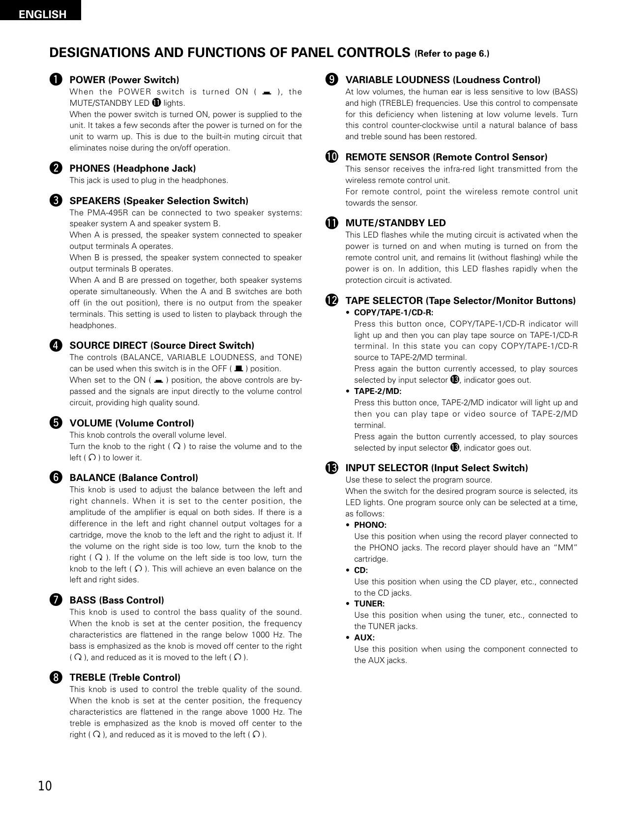
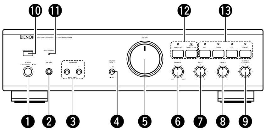
DESIGNATIONS AND FUNCTIONS OF PANEL CONTROLS (Refer to page 6.)
1 POWER (Power Switch)
When the POWER switch is turned ON ( - ), the MUTE/STANDBY LED 1 lights.
When the power switch is turned ON, power is supplied to the unit. It takes a few seconds after the power is turned on for the unit to warm up. This is due to the built-in muting circuit that eliminates noise during the on/off operation.
2 PHONES (Headphone Jack)
This jack is used to plug in the headphones.
SPEAKERS (Speaker Selection Switch)
The PMA-495R can be connected to two speaker systems: speaker system A and speaker system B.
When A is pressed, the speaker system connected to speaker output terminals A operates.
When B is pressed, the speaker system connected to speaker output terminals B operates.
When A and B are pressed on together, both speaker systems operate simultaneously. When the A and B switches are both off (in the out position), there is no output from the speaker terminals. This setting is used to listen to playback through the headphones.
4 SOURCE DIRECT (Source Direct Switch)
The controls (BALANCE, VARIABLE LOUDNESS, and TONE) can be used when this switch is in the OFF (■) position.
When set to the ON ( ) position, the above controls are bypassed and the signals are input directly to the volume control circuit, providing high quality sound.
VOLUME (Volume Control)
This knob controls the overall volume level.
Turn the knob to the right (O) to raise the volume and to the left (O) to lower it.
6 BALANCE (Balance Control)
This knob is used to adjust the balance between the left and right channels. When it is set to the center position, the amplitude of the amplifier is equal on both sides. If there is a difference in the left and right channel output voltages for a cartridge, move the knob to the left and the right to adjust it. If the volume on the right side is too low, turn the knob to the right (Ω). If the volume on the left side is too low, turn the knob to the left (Ω). This will achieve an even balance on the left and right sides.
BASS (Bass Control)
This knob is used to control the bass quality of the sound. When the knob is set at the center position, the frequency characteristics are flattened in the range below 1000Hz . The bass is emphasized as the knob is moved off center to the right () , and reduced as it is moved to the left () .
TREBLE (Treble Control)
This knob is used to control the treble quality of the sound. When the knob is set at the center position, the frequency characteristics are flattened in the range above 1000Hz . The treble is emphasized as the knob is moved off center to the right () , and reduced as it is moved to the left () .
9 VARIABLE LOUDNESS (Loudness Control)
At low volumes, the human ear is less sensitive to low (BASS) and high (TREBLE) frequencies. Use this control to compensate for this deficiency when listening at low volume levels. Turn this control counter-clockwise until a natural balance of bass and treble sound has been restored.
10 REMOTE SENSOR (Remote Control Sensor)
This sensor receives the infra-red light transmitted from the wireless remote control unit.
For remote control, point the wireless remote control unit towards the sensor.
1 MUTE/STANDBY LED
This LED flashes while the muting circuit is activated when the power is turned on and when muting is turned on from the remote control unit, and remains lit (without flashing) while the power is on. In addition, this LED flashes rapidly when the protection circuit is activated.
12 TAPE SELECTOR (Tape Selector/Monitor Buttons)
COPY/TAPE-1/CD-R:
Press this button once, COPY/TAPE-1/CD-R indicator will light up and then you can play tape source on TAPE-1/CD-R terminal. In this state you can copy COPY/TAPE-1/CD-R source to TAPE-2/MD terminal.
Press again the button currently accessed, to play sources selected by input selector 13, indicator goes out.
- TAPE-2/MD:
Press this button once, TAPE-2/MD indicator will light up and then you can play tape or video source of TAPE-2/MD terminal.
Press again the button currently accessed, to play sources selected by input selector 13, indicator goes out.
13 INPUT SELECTOR (Input Select Switch)
Use these to select the program source.
When the switch for the desired program source is selected, its LED lights. One program source only can be selected at a time, as follows:
PHONO:
Use this position when using the record player connected to the PHONO jacks. The record player should have an "MM" cartridge.
CD:
Use this position when using the CD player, etc., connected to the CD jacks.
TUNER:
Use this position when using the tuner, etc., connected to the TUNER jacks.
AUX:
Use this position when using the component connected to the AUX jacks.
OPERATION
PREPARATION
1. CHECKING CONNECTIONS
- Make sure that all the connections are proper by referring to the back panel. (Fig. 2~3)
- Check the polarity (positive and negative) of connections, and the directivity of stereo separation (right cord to right channel terminal, and left cord to left channel terminal).
- Check the directivity of pin cord connection.
2. SETTING OF EACH KNOB
- Turn the volume control knob ⑤ counterclockwise, to left.
- Set the rotary knob to "flat" or "center position".
- Set SOURCE DIRECT ④ to "OFF (■)".
- Press the TAPE MONITOR switch 12 to turn the LED off.
- Turn on the speaker selection switch for desired speaker system (A or B).
After checking the above items, turn on the power, the amplifier is set in the ready mode in a few seconds.
PLAYING A RECORD
- Set the INPUT SELECTOR switch 13 to "PHONO".
- Operate the turntable and play the record.
- Turn the volume and tone controls to yield an appropriate volume and sound quality.
PLAYBACK OF CD PLAYER
- Set the INPUT SELECTOR switch 13 to "CD".
- Operate the CD player.
- Turn the volume and tone controls to yield an appropriate volume and sound quality.
RECEPTION OF RADIO PROGRAMS
- Set the INPUT SELECTOR switch 13 to "TUNER".
- Operate the tuner to receive a radio program.
- Turn the volume and tone controls to yield an appropriate volume and sound quality.
CONNECTIONS OF AUDIO EQUIPMENT TO AUX TERMINALS
- Set the INPUT SELECTOR switch 15 to "AUX" Position.
- Operate the Audio equipment Systems.
- Turn the volume and tone controls to yield an appropriate volume and sound quality.
PLAYBACK WITH TAPE DECK
- Set the TAPE MONITOR switch 12 to "COPY/TAPE-1/CD-R" or "TAPE-2/MD".
- Operate the Tape Deck.
- Turn the volume and tone controls to yield an appropriate volume and sound quality.
RECORDING WITH TAPE DECK
The source to be recorded is selected by the INPUT SELECTOR switch 13.
COPYING FROM ONE TAPE TO ANOTHER
To copy from COPY/TAPE-1/CD-R to TAPE-2/MD, press the COPY/TAPE-1/CD-R switch 12.
NOTE:
Copying is not possible from TAPE-2/MD to COPY/TAPE-1/CD-R.
MONITORING THE RECORDING
(If a 3-head tape deck is used, the sound being recorded can be monitored during the recording.)
Use the TAPE MONITOR switches 12 to select the tape deck onto which the sound is being recorded.
The LED for the selected tape deck lights.
CAUTION
Protective Circuit
This set is equipped with a high speed protective circuit. This circuit protects the internal circuitry from damage due to large currents flowing when the speaker jacks are not completely connected or when an output is generated by a short circuit. This protective circuit's operation cuts off the output to the speakers. In such a case, be sure to turn the power to the set off and check the connections to the speakers. Then turn the power on again. After muting for a few seconds, the set will operate normally.
The accessory Remote Control Unit is used to control the amplifier from a convenient distance.
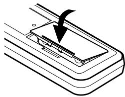
(1) Inserting the Dry Cell Batteries
- Remove the battery cover on the Remote Control Unit.
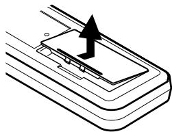
- Insert two dry cell batteries as shown in the diagram on the battery supply unit.
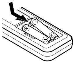
- Replace the battery cover.
(2) Directions for use
Notes on Battery Usage
- RC-176 uses the size R6P (AA) dry cell batteries.
- The batteries will need to be replaced approximately once a year. This will depend upon how often the Remote Control Unit is used.
- If, in less than a year from the time new batteries were inserted, the Remote Control Unit falls to operate the Amplifier from a nearby position, it is time to replace the batteries.
(The included battery is only for verifying operation. Replace it with a new battery as soon as possible.)
- Insert the batteries properly, following the polarity diagram inside the battery compartment.
-
Batteries are prone to damage and leakage. Therefore:
-
Do not mix new batteries with used ones.
- Do not mix different types of batteries.
-
Do not jumper opposite poles of the batteries, expose them to heat, break them open, nor expose them to open fire.
-
If the batteries have leaked, remove any traces of battery fluid from the battery compartment wiping thoroughly with a dry cloth. Then insert new batteries.
-
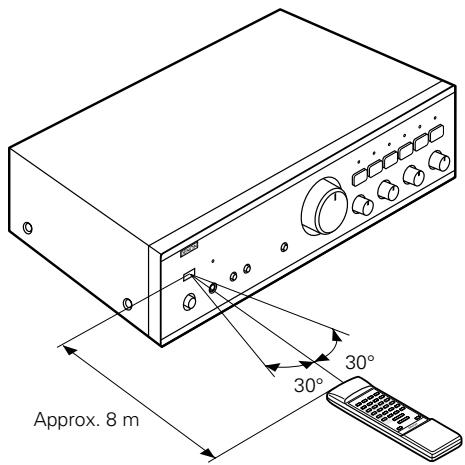
Operate the Remote Control Unit while pointing it towards the Remote Control Sensor on the Amplifier as shown in the diagram on the left.
- The Remote Control Unit can be used at distances up to about 8 meters in a straight line from the amplifier. This distance will decrease if there are obstructions blocking the infra-red light transmission or if the Remote Control Unit is not directed straight at the amplifier.
Note on operation
- Do not press the operating buttons on the Amplifier and the Remote Control Unit at the same time. This will cause misoperation.
- Operation of the Remote Control Unit will become less effective or erratic if the infrared Remote Control Sensor on the Amplifier is exposed to strong light or if there are obstructions between the Remote Control Unit and the sensor.
- In case you operate a VCR, TV or other components by remote control, do not operate buttons on two different remote control units at the same time. This will cause misoperation.
Besides being able to operate the PMA-495R amplifier with this Remote Control Unit, you can also operate a DENON cassette deck and CD player from this handy full-system Remote Control Unit.
Remote control section
Full-system Remote Control Unit
The full-system Remote Control Unit operates all major functions of the Amplifier, such as function switching, volume control. But that's not all! The same control pad can also control the major functions of a DENON CD player and cassette deck and tuner when combined with the PMA-495R to create a remarkably ergonomic and versatile DENON system with all the quality sound reproduction that the devoted audiophile expects.
Remote Control Unit RC-176 supplied with the PMA-495R
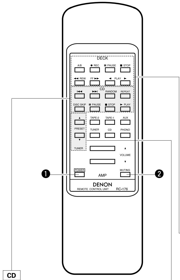
| ▶PLAY | PLAY button |
| ■STOP | STOP button |
| I←↓ | Reverse Track Search button |
| ▶→I | Forward Track Search button |
| RANDOM | Refer to the operating instructions of your DENON CD player |
| REPEAT | |
| DISC SKIP | |
| ■PAUSE | PAUSE button |
1 POWER button
- When the main unit's POWER switch is set to the ON/STANDBY position ( ), press this to turn the PMA495R's power on and off.
- When the power is turned off from the remote control unit, the main unit's MUTE/STANDBY LED remains lit, but the input LED turns off, indicating that the PMA-495R is in the standby mode.
- When the main unit's POWER switch is set to the OFF position (■) after turning the power off from the remote control unit and then set back to the ON/STANDBY position (■), the PMA-495R is set to the operating mode.
This button will not function if there is a power failure, if the power cord is not plugged in, or when using an audio timer.
2 MUTING button
Pressing this switch will activate the muting condition and no signals will be output to the speakers.
Other buttons
Other buttons are exclusively for the PMA-495R, and function in the same way as the corresponding buttons on the set.
DECK
| PLAY▶ | PLAY button |
| ▲ PLAY (REV) | PLAY (REV) button |
| ■ STOP | STOP button |
| ▲ REW | REWIND button |
| FF▶ | FF button |
| ● REC | Refer to the operating instructions of your DENON tape deck. |
| ■ PAUSE | |
| A/B | A/B DECK SELECT button |
TUNER
PRESET buttons
Press this button to move up or down among the preset station numbers.
- The RC-176 Remote Control Unit can control CD players and cassette decks manufactured by DENON.
- Note that operation may not be possible for some models.
- Buttons are conveniently separated into groups, each group controlling one specific component. The groups are AMP, FUNCTION, CD, DECK and TUNER etc..
For details on operating other components, refer to the operating instructions for the CD player and/or cassette deck.
CAUTION:
- If the power is turned off with the Remote Control Unit, the set is switched to the power stand-by state. If you are absent for a long period of time, unplug the power cord.
- Only the MUTE/STANDBY LED 11 lights when in the power stand-by mode.
- You may experience erratic operation of the Remote Control Unit if it is operated in fluorescent light and direct sunlight, in particular if this light strikes the Remote Control Sensor on the Amplifier. However, this is not a malfunction, and if this should happen, simply protect the sensor against such light.
10 REMOTE SENSOR (Sensore a distance)
- PHONO (Auriculares):
WEERGAVE MET HET TAPE-DECK
OPNAME MET HET TAPE-DECK
WERKING AFSTANDSBEDIERING
Indikatordioden for det valda dpacket tands.
WARNING
Skyddskrets
- INTEGRATED STEREO AMPLIFIER
- PMA-495R
- "SERIAL NO.
- PLEASE RECORD UNIT SERIAL NUMBER ATTACHED TO THE REAR OF THE CABINET FOR FUTURE REFERENCE"
- CAUTION:
- CAUTION RISK OF ELECTRIC SHOCK DO NOT OPEN
- - DECLARATION OF CONFORMITY
- Please check to make sure the following items are included with the main unit in the carton:
- HINWEIS:
- PANEL FRONTAL
- VOORPANEEL
- FRAMSIDA
- PAINEL FRONTAL
- PANEL TRASERO
- ACHTERPANEL
- BAKSIDA
- PAINEL TRAZEIRO
- Ground Wire
- rdungskabel
- DESIGNATIONS AND FUNCTIONS OF PANEL CONTROLS (Refer to page 6.)
- POWER (Power Switch)
- PHONES (Headphone Jack)
- SPEAKERS (Speaker Selection Switch)
- SOURCE DIRECT (Source Direct Switch)
- VOLUME (Volume Control)
- BALANCE (Balance Control)
- BASS (Bass Control)
- TREBLE (Treble Control)
- VARIABLE LOUDNESS (Loudness Control)
- REMOTE SENSOR (Remote Control Sensor)
- MUTE/STANDBY LED
- TAPE SELECTOR (Tape Selector/Monitor Buttons)
- COPY/TAPE-1/CD-R:
- - TAPE-2/MD:
- INPUT SELECTOR (Input Select Switch)
- PHONO:
- CD:
- TUNER:
- AUX:
- OPERATION
- PREPARATION
- CHECKING CONNECTIONS
- SETTING OF EACH KNOB
- PLAYING A RECORD
- PLAYBACK OF CD PLAYER
- RECEPTION OF RADIO PROGRAMS
- CONNECTIONS OF AUDIO EQUIPMENT TO AUX TERMINALS
- PLAYBACK WITH TAPE DECK
- RECORDING WITH TAPE DECK
- COPYING FROM ONE TAPE TO ANOTHER
- NOTE:
- MONITORING THE RECORDING
- CAUTION
- Protective Circuit
- Inserting the Dry Cell Batteries
- Directions for use
- Notes on Battery Usage
- Note on operation
- Besides being able to operate the PMA-495R amplifier with this Remote Control Unit, you can also operate a DENON cassette deck and CD player from this handy full-system Remote Control Unit.
- Remote Control Unit RC-176 supplied with the PMA-495R
- POWER button
- MUTING button
- Other buttons
- TUNER
- PRESET buttons
- REMOTE SENSOR (Sensore a distance)
- WEERGAVE MET HET TAPE-DECK
- OPNAME MET HET TAPE-DECK
- WERKING AFSTANDSBEDIERING
- WARNING
- Skyddskrets
Brand : DENON
Model : PMA-495R
Category : Audio Amplifier