
PMA-1500RII - Audio Amplifier DENON - Free user manual and instructions
Find the device manual for free PMA-1500RII DENON in PDF.
| Product type | Integrated stereo audio amplifier |
| Brand | DENON |
| Model | PMA-1500RII |
| Output power (8 ohms, 20 Hz-20 kHz) | 70 W + 70 W (THD 0.07 %) |
| Output power (4 ohms, 1 kHz) | 140 W + 140 W (DIN, THD 0.7 %) |
| Compatible speaker impedance (one system) | 4 - 16 Ω |
| Compatible speaker impedance (A+B simultaneous) | 8 - 16 Ω |
| Inputs | PHONO MM/MC, CD, TUNER, DVD/AUX, TAPE-1/DAT, TAPE-2/MD |
| Outputs | Headphone jack, PRE OUT, speakers A and B, REC OUT (TAPE-1/DAT, TAPE-2/MD) |
| PHONO MM input sensitivity | 2.5 mV / 47 kΩ |
| PHONO MC input sensitivity | 200 µV / 100 Ω |
| Line input sensitivity | 150 mV / 47 kΩ |
| Signal-to-noise ratio (source direct, line) | 110 dB |
| Frequency response | 5 Hz - 100 kHz (+0, -3 dB) |
| Power consumption | 305 W (IEC) |
| Standby power consumption | 2 W max |
| Power supply | Mains 230 V~ 50/60 Hz |
| Remote control | Infrared, R6P (AA) batteries x2, range 8 m |
| Dimensions (remote control) | 54 x 155 x 29 mm |
| Weight (remote control) | 100 g (with batteries) |
| Maintenance | Clean with a dry, soft cloth. Do not use chemical products. |
| Safety | Do not touch speaker terminals while powered. Ensure adequate ventilation (10 cm minimum around the device). |
Frequently Asked Questions - PMA-1500RII DENON
User questions about PMA-1500RII DENON
0 question about this device. Answer the ones you know or ask your own.
Ask a new question about this device
Download the instructions for your Audio Amplifier in PDF format for free! Find your manual PMA-1500RII - DENON and take your electronic device back in hand. On this page are published all the documents necessary for the use of your device. PMA-1500RII by DENON.
USER MANUAL PMA-1500RII DENON
INTEGRATED AMPLIFIER
PMA-1500RII
OPERATING INSTRUCTIONS
BEDIENUNGSANLEITUNG
MODE D'EMPLOI
ISTRUZIONI PER L'USO
TO PREVENT FIRE OR SHOCK HAZARD, DO NOT EXPOSE THIS APPLIANCE TO RAIN OR MOISTURE.
"SERIAL NO.
PLEASE RECORD UNIT SERIAL NUMBER ATTACHED TO THE REAR OF THE CABINET FOR FUTURE REFERENCE"
CAUTION:
- The ventilation should not be impeded by covering the ventilation openings with items, such as newspapers, table-cloths, curtains, etc.
- No naked flame sources, such as lighted candles, should be placed on the apparatus.
- Please be care the environmental aspects of battery disposal.
- The apparatus shall not be exposed to dripping or splashing for use.
- No objects filled with liquids, such as vases, shall be placed on the apparatus.

CAUTION
RISK OF ELECTRIC SHOCK DO NOT OPEN

CAUTION:
TO REDUCE THE RISK OF ELECTRIC SHOCK, DO NOT REMOVE COVER (OR BACK). NO USER-SERVICEABLE PARTS INSIDE. REFER SERVICING TO QUALIFIED SERVICE PERSONNEL.

The lightning flash with arrowhead symbol, within an equilateral triangle, is intended to alert the user to the presence of uninsulated "dangerous voltage" within the product's enclosure that may be of sufficient magnitude to constitute a risk of electric shock to persons.

The exclamation point within an equilateral triangle is intended to alert the user to the presence of important operating and maintenance (servicing) instructions in the literature accompanying the appliance.
- DECLARATION OF CONFORMITY
We declare under our sole responsibility that this product, to which this declaration relates, is in conformity with the following standards:
EN60065, EN55013, EN55020, EN61000-3-2 and EN61000-3-3.
Following the provisions of 73/23/EEC, 89/336/EEC and 93/68/ EEC Directive.
Allow for sufficient heat dispersion when installed on a rack.
- Handle the power cord carefully.
Hold the plug when unplugging the cord.

* (For sets with ventilation holes)
- Do not obstruct the ventilation holes.
Die Belüttungsöffnungen)duren nicht verdeckt werden. - Ne pas obstruer les troughs d'airation.
Non coprite i fori di ventilazione. - No obstruya los orificios de ventilación.
- De ventilatieopengen mogen nicht worden beblokkeerd.
Tapp inte till ventilationsöppningarna. - Não obtrua os orificios de ventilação.

- Do not let foreign objects in the set.
- Keine fremden Gegenstände in das Gerätkommen halten.
- Ne pas laisser des objets étrangers dans l'appareil.
- E' importante che nessun oggetto è inserto all'interno dell'unità.
- NoADEjebotonosextraoindtrodelequipo.
- Laat geen vreemde voorwerpen in dit apparaat vallen.
- Se till att främnde foremål inte tränger in i apparaten.
- Não deixe objetivos estranhos no aparecido.

- Do not let insecticides, benzene, and thinner come in contact with the set.
- Lassen Sie das Gerät nicht mit Insektiziden, Benzin oder Verdünningsmitteln in Berührung kommt.
- Ne pasmettre en contact des insecticides, du benzene et un diluant avec l'appareil.
Assicuratevchi che l'unità non venga in dato con insettici di, benzolo o solventi. - No permitted contacto de insecticidas, gasolina y diluyentes con el equipo.
- Laat geen insetkenverdelgende middelen, benzine of verfverdunner met dit apparaat in kontakt komen.
- Se till att inte insektsmedel på spraybruk, bensen och thinnerkommen ikontakt med apparatens hölje.
- Não permita que insetucidas, benzina e dissol-ventearemtemencountercomoparelho.

- Never disassemble or modify the set in any way.
Versuchen Sie niemals das Gerät auseinander zunehmen oder auf jegliche Art zu verändern. - Ne jamais démonter ou modifier l'appareil d'une manière ou d'une autre.
Non smontate mai, nè modifie l'unità in nessun modo. - Nunca desarme o modifique el equipo de ninguna manera.
- Nooit dit apparaat demonteren of op andere wijze modifierten.
- Ta inte isär apparaten och försök inte bygga om den.
- Nunca desmonte ou modifique o aparelho de alguma forma.
NOTE:
- Always keep the POWER switch on the main unit turned on.
- Turn the power on and off from the remote control unit.
- Unplug the power supply cord when you do not plan to use the unit for a long period of time.
CAUTION:
Only when the power LED is lit red, this means that the power is turned off with remote control unit. Turn the power on from the remote control unit.
HINWEIS:
Please check to make sure the following items are included with the main unit in the carton:
(1) Operating Instructions. 1
(2) Remote Control Unit (RC-885) 1
(3) Batteries R6P (AA) 2
(4) Power Supply Cord 1
(5) Service Station List 1
—INHALT —
For heat dispersal, leave at least 10~cm of space between the top, back and sides of this unit and the wall or other components.
1 DESIGNATIONS AND FUNCTIONS OF PANEL CONTROLS (Refer to page 5)
Power switch (POWER)
When the power switch is turned ON ( ), the power LED 11 lights.
When the power switch is turned ON, power is supplied to the unit. It takes a few seconds after the power is turned on for the unit to warm up. This is due to the built-in muting circuit that eliminates noise during the on/off operation.
2 Headphone jack (PHONES)
This jack is used to plug in the headphones.
(The SPEAKER output is turned off when the headphones are plugged in.)
To prevent hearing loss, do not raise the volume level excessively when using headphones.
3 Bass control (BASS)
This knob is used to control the bass quality of the sound. When the knob is set at the center position, the frequency characteristics are flattened in the range below 1000Hz . The bass is emphasized as the knob is moved off center to the right () , and reduced as it is moved to the left () .
4 Treble control (TREBLE)
This knob is used to control the treble quality of the sound. When the knob is set at the center position, the frequency characteristics are flattened in the range above 1000Hz . The treble is emphasized as the knob is moved off center to the right () , and reduced as it is moved to the left () .
NOTE:
When the Volume control ⑦ is turned right (C) from the center position, the adjustment range of the BASS ③, TREBLE ④ and LOUDNESS ⑤ controls decreases. If the Volume control ⑦ is turned fully right the bass and treble cannot be adjusted.
Loudness Switch (LOUDNESS)
When the volume is low, it is difficult for the human ear to clearly distinguish notes in the low and high frequency ranges. The loudness switch allows a simple "ontouch" correction of this difficulty. Press the loudness switch ON ( ) when listening to music at a low volume. The low notes and high notes will be corrected to produce a natural sound.
Balance control (BALANCE)
This knob is used to adjust the balance between the left and right channels.
When it is set to the center position, the amplitude of the amplifier is equal on both sides. If the volume on the right side is too low, turn the knob to the right () . If the volume on the left side is too low, turn the knob to the left () . This will achieve an even balance on the left and right sides.
Volume control (VOLUME)
This knob controls the overall volume level.
Turn the knob to the right () to raise the volume and to the left () to lower it.
Recording output select switch (REC OUT SELECTOR)
Use this to select the output source for recording onto a tape deck, etc.
- TAPE-2▶1:
Use this position when making copies of tapes using two tape decks. The input signal from the deck connected to the TAPE-2/MD input terminals is fed to the TAPE-1/DAT REC OUT terminals.
- TAPE-1▶2:
Use this position when making copies of tapes using two tape decks. The input signal from the deck connected to the TAPE-1/DAT input terminals is fed to the TAPE-2/MD REC OUT terminals.
PHONO:
Used to recording from the turntable.
CD:
Used to recording from the CD player.
TUNER:
Used to recording from the tuner.
DVD/AUX:
Used to recording component that connected to the DVD/ AUX terminals.
Input select switch (INPUT SELECTOR)
This switch is used to select the input signal for the program source.
TAPE-2/MD:
Use this position when using the tape deck, etc., connected to the TAPE-2/MD terminals.
TAPE-1/DAT:
Use this position when using the tape deck, etc., connected to the TAPE-1/DAT terminals.
PHONO:
Use this position when using the record player connected to the PHONO terminals.
Use the CARTRIDGE selection switch 17 to switch the sensitivity to correspond to the cartridge type being used.
CD:
Used to listen a compact disc player or other component that is connected to the CD terminals.
TUNER:
Used to play a component such as an FM/AM tuner or a TV tuner that is connected to the TUNER terminals.
DVD/AUX:
Used to play a component such as a HiFi video player, TV tuner or tape deck that is connected to the DVD/AUX terminals.
10 Source direct switch (SOURCE DIRECT)
The controls (BASS 3, TREBLE 4, LOUDNESS 5 and BALANCE 6) can be used when this switch is in the OFF (■) position.
When set to the ON (.) position, the above controls are by passed and the signals are input directly to the volume control circuit, providing high quality sound.
11 Power LED
The LED indicates the set's operating mode.
| Main unit power switch | Main unit mode | LED color |
| ON (▶) | Operating | Lit orange |
| Mute | Flashing green ⇌ orange | |
| Standby (power off by remote control) | Lit red | |
| OFF (■) | Off |
The mute mode is set for several seconds when the main unit's power switch is turned ON (.) or when the standby mode is canceled by the remote control unit.
Remote Control Sensor (REMOTE SENSOR)
This sensor receives the infra-red light transmitted from the wireless remote control unit.
For remote control, point the wireless remote control unit towards the sensor.
13 Iput terminals (INPUTS)
These are input terminals for CD players, turntables, AM/FM tuners, tape decks or other playback components.
NOTES:
- The PHONO input terminals are equipped with a short pin-plug. Remove this plug to connect a record player.
Store the removed short pin-plug in a safe place so as not to lose it. - Do not plug a short pin plug into the REC (recording output) terminals. Doing so will result in a loss of sound and may damage connected equipment.
14 Tape playback and recording terminals (TAPE-1/DAT, TAPE-2/MD)
Playback and Recording Terminals
- Playback Terminals (PB).
- Recording Terminals (REC).
15 Pre out terminals (PRE OUT)
Use these when adding a power amplifier, a subwoofer with built-in power amplifier, etc.
Connect these PRE OUT terminals to the input terminals on the additional power amplifier, subwoofer, etc.
NOTE:
Signals are output from the PRE OUT terminals even when using headphones.
If you wish to stop the signals, do so by operating the connected unit (power amplifier, etc.).
Speaker system terminals (SPEAKER SYSTEMS)
Connect the speaker systems here.
17 Cartridge selection switch (CARTRIDGE)
This switch is set according to the type of player cartridge to be used.
Set this switch to MM (■) or MC (■) according to the type of cartridge used on your turntable.
Ground terminal (SIGNAL GND)
Connect the turntable's ground wire here.
NOTE:
This terminal is used to reduce noise when a turntable, etc., is connected. It does not provide complete grounding.
19 Attachment plug receptacles (AC OUTLETS)
AC outlets are used for connecting amplifier component units, such as tuner, turntable, tape deck, etc.
- SWITCHED
These outlets are turned ON/OFF when main power switch is turned on/off.
20 AC inlet receptacle (AC IN)
Connect the included power supply cord here.
Do not use any other cord than the provided power supply cord.
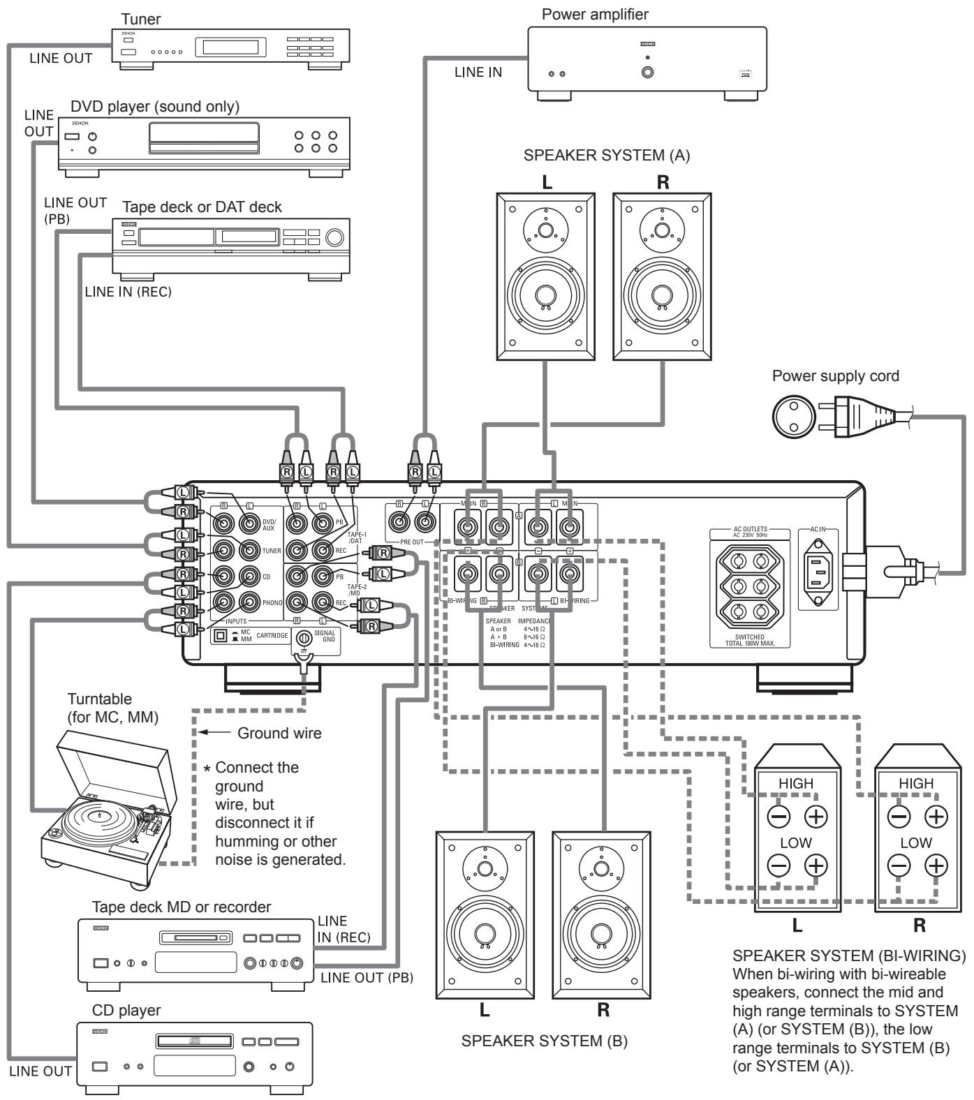
2 CONNECTIONS
Connecting the speakers
Speaker impedance
- When using speaker systems A and B separately, speakers with an impedance of 4 to 16 / ohms can be connected.
- When bi-wiring with bi-wireable speaker system, speakers with an impedance of 4 to 16/ohms can be connected.
- Note that when using two sets of speaker systems together (A + B), using speakers with an impedance other than between 8 to 16 Ω/ohms can result in damage.
Note that this unit is not equipped with a switch for selecting the speaker system. The A and B speaker output terminals are connected in parallel.
- The protective circuit may be activated if speakers with other impedances are connected.
■ Be sure to connect the cords between the speaker terminals and speaker systems with the same polarities ( to , to ). If not, the central sound will be weak and the position of the different instruments will not be clear, diminishing the stereo effect.
- When connecting the speakers, be sure that the core wires of the speaker cords do not stick out from the terminals and touch other terminals, each other or the rear panel.
- Connecting the speaker cords
- Peel off the sheathing from the end of the cord.
- Twist the core wires.
- Turn the speaker terminal counterclockwise to loosen it.
- Insert the core wires entirely, then turn the terminal clockwise to tighten it.
CAUTION:
NEVER touch the speaker terminals when the power is on.
Doing so could result in electric shocks.
NOTE:
Protector Circuit
This set is equipped with a built-in high speed protector circuit. This circuit protects the speakers should the amplifier's outputs be short-circuited or the surrounding temperature be abnormal. When the protector circuit is activated, the speaker output is automatically interrupted. Should this happen, turn off the set's power, check the speaker cable connections once again, then turn the power back on. The set will operate normally once the muting circuit turns off after several seconds.
Cautions on Connections
- Do not plug in the power suppy cord until all connections are completed.
- Be sure to connect the left and right channels properly.
- Insert the plugs securely. Incomplete connections can result in noise.
-
Use the SWITCHED AC OUTLETS to plug in audio components. Do not use them for hair dryers or other appliances.
-
Note that placing the pin plug cords next to power supply cords or near power transformers may result in humming or other noise.
- The PHONO input jacks have an extremely high sensitivity, so avoid turning up the volume when no pin plug cords are connected. Doing so may result in induction humming (booming) from the speakers. When pin plug cords are not connected, insert the included short-circuit pin plug.
3 OPERATION (Refer to Page 5)
PREPARATION
1. CHECKING CONNECTIONS
- Make sure that all the connections are proper by referring to the rear panel.
- Check the polarity (positive and negative) of connections, and the directivity of stereo separation (right cord to right channel terminal, and left cord to left channel terminal).
- Check the directivity of pin cord connection.
2. SETTING OF EACH KNOB
- Turn the volume control knob ⑦ left (○), to minimum position.
- Set the tone controls ③, ④ and balance control ⑥ to center position.
- Set the LOUDNESS switch ⑤ to "OFF (■)".
- Set the SOURCE DIRECT switch 10 to "OFF (■)".
After checking the above items, turn on the power, the amplifier is set in the ready mode in a few seconds.
PLAYING A RECORD
- Set the CARTRIDGE selection switch "MC (■)" on "MM (■)".
- Set the INPUT SELECTOR switch 9 to "PHONO".
- Operate the turntable and play the record.
- Turn the volume ⑦ and tone controls ③, ④ and balance control ⑥ to yield an appropriate volume and sound quality.
PLAYBACK OF CD PLAYER
- Set the INPUT SELECTOR switch ⑨ to "CD".
- Operate the CD player.
- Turn the volume 7 and tone controls 3, 4 and balance control 6 to yield an appropriate volume and sound quality.
RECEPTION OF RADIO PROGRAMS
- Set the INPUT SELECTOR switch to "TUNER".
- Operate the tuner to receive a radio program.
- Turn the volume 7 and tone controls 3, 4 and balance control 6 to yield an appropriate volume and sound quality.
CONNECTIONS OF AUDIO EQUIPMENT TO DVD/ AUX TERMINALS
- Set the INPUT SELECTOR switch 9 to "DVD/AUX" position.
- Operate the Audio equipment Systems.
- Turn the volume ⑦ and tone controls ③, ④ and balance control ⑥ to yield an appropriate volume and sound quality.
PLAYBACK WITH TAPE DECK, DAT, MD
- Set the INPUT SELECTOR switch to "TAPE-1/DAT" or "TAPE-2/MD".
- Operate the Tape Deck, DAT, MD.
- Turn the volume ⑦ and tone controls ③, ④ and balance control ⑥ to yield an appropriate volume and sound quality.
RECORDING WITH TAPE DECK, DAT, MD
- Set the REC OUT SELECTOR switch ⑧ to the program source you wish to record.
- Start the playback of the program source.
- Start recording with the component connected to "TAPE-1/DAT" or "TAPE-2/MD".
- In the PMA-1500RII, the REC OUT signal and the speaker (headphone) signal are output via separate circuits so that knobs and switches related to the tone and volume have no effect what so ever on the sound that is recorded. Also, since the recording function is selected by the REC OUT SELECTOR switch ⑧, the free program source can be played through the speakers (or headphones) even during recording.
MONITORING THE RECORDING
- A recording in progress can be monitored if a tape deck with three individual heads for recording and playback is used. A tape deck in which a common head is used for both recording and playback cannot be used to monitor recording.
When a recording is being made using TAPE-1/DAT, selecting TAPE-1/DAT with the INPUT SELECTOR will engage the RECORDING MONITOR and permit a check of the recording condition.
The accessory Remote Control Unit is used to control the amplifier from a convenient distance.
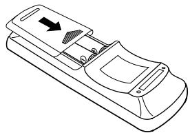
Inserting the Dry Cell Batteries
- Remove the battery cover on the Remote Control Unit.
- Insert two dry cell batteries as shown in the diagram on the battery supply unit.
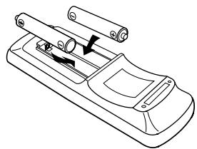
- Replace the battery cover.
Directions for use
Note on operation
- Do not press the operating buttons on the Amplifier and the Remote Control Unit at the same time. This will cause misoperation.
Operation of the Remote Control Unit will become less effective or erratic if the infrared Remote Control Sensor on the Amplifier is exposed to strong light or if there are obstructions between the Remote Control Unit and the sensor. - In case you operate a VCR, TV or other components by remote control, do not operate buttons on two different remote control units at the same time. This will cause misoperation.
Besides being able to operate the PMA-1500RII Integrated-amplifier with this Remote Control Unit, you can also operate a DENON cassette deck, MD recorder, tuner and CD player with this handy full-system Remote Control Unit.
Notes on Battery Usage
RC-885 uses the size R6P (AA) dry cell batteries.
The batteries will need to be replaced approximately once a year. This will depend upon how often the Remote Control Unit is used.
If, in less than a year from the time new batteries were inserted, the Remote Control Unit fails to operate the Amplifier from a near-by position, it is time to replace the batteries.
The included battery is only for verifying operation. Replace it with a new battery as soon as possible.
Insert the batteries properly, following the polarity diagram inside the battery compartment.
Batteries are prone to damage and leakage. Therefore:
- Do not mix new batteries with used ones.
- Do not mix different types of batteries.
- Do not jumper opposite poles of the batteries, expose them to heat, break them open, nor expose them to open fire.
If the batteries have leaked, remove any traces of battery fluid from the battery compartment wiping thoroughly with a dry cloth. Then insert new batteries.
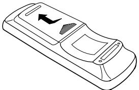
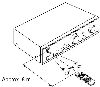
- Operate the Remote Control Unit while pointing it towards the Remote Control Sensor on the Amplifier as shown in the diagram on the left.
- The Remote Control Unit can be used at distances up to about 8 meters in a straight line from the amplifier. This distance will decrease if there are obstructions blocking the infra-red light transmission or if the Remote Control Unit is not directed straight at the amplifier.
Remote Control Unit RC-885 supplied with the PMA-1500RII
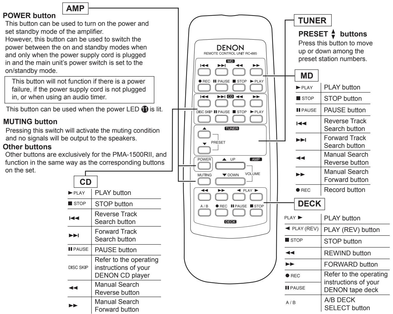
- The RC-885 Remote Control Unit can control CD players, MD recorder, tuners and cassette decks manufactured by DENON.
Note that operation may not be possible for some models. - Buttons are conveniently separated into groups, each group controlling one specific component. The groups are AMP, CD, MD, DECK and TUNER.
For details on operating other components, refer to the operating instructions for the CD player, MD recorder, tuners and cassette deck.
CAUTION:
- If the power is turned off with the Remote Control Unit, the set is switched to the power stand-by state. If you are absent for a long period of time, unplug the power supply cord.
- Only the power LED 11 lights when in the power stand-by mode.
- You may experience erratic operation of the Remote Control Unit if it is operated in fluorescent light and direct sunlight, in particular if this light strikes the Remote Control Sensor on the Amplifier. However, this is not a malfunction, and if this should happen, simply protect the sensor against such light.
5 TROUBLESHOOTING
Check the following before assuming there is a problem with the set.
- Are all connections proper?
- Is the set being operated as described in the operating instructions?
- Are the speakers and input components being operated properly?
If the set does not seem to be operating properly, check the points listed below. If these points do not apply, the set may be damaged. Turn off the power immediately and contact your store of purchase.
| Symptom | Cause | Measures | Page |
| Common problems arising when listening to the CD,MD,records, tapes, and FM broadcasts, etc. | |||
| Power LED does not light and no sound is produced when POWER switch is turned on. | • Power supply cord is not con- nected. | • Check that the cord is plugged in. | 10 |
| Power LED lights but no sound is produced. | • Speaker cords not properly con- nected. • INPUT SELECTOR not set to proper position. • VOLUME control turned down. | • Connect securely. • Set to the proper position. • Set to an appropriate level. | 9, 10 8, 11 8, 11 |
| Sound is not produced from one side only. | • Speaker cords not properly con- nected. • Input cords not properly connected. • Left/right balance improperly adjusted. | • Connect securely. • Connect securely. • Adjust the BALANCE control. | 9, 10 10 8, 11 |
| Volume level is different when listening to tuner and records. | • Tuner and record outputs different. | • Adjust the tuner output to the turn- table's output (if the tuner is equipped with an output control). | - |
| Positions of instruments inverted for stereo sources. | • Left and right speakers or input cords inverted. | • Check the left/right connections. | 9, 10 |
| Problems occurring when playing records. | |||
| Booming sound produced when playing records. | • Turntable's ground wire not con- nected. • Input cords not properly connected to PHONO terminals. • Influence from a TV or VCR near the turntable. | • Connect securely. • Connect securely. • Change the position of installation. | 10 10 - |
| Howling produced when volume is turned up while playing records. | • Turntable and speaker systems are too close. • Floor is soft and vibrates easily. | • Move speaker systems as far away as possible. • Use cushions to absorb the vibra- tions transmitted from the floor to the speakers. If the turntable does not include insulators, use audio insulators, available in stores. | - - |
| Sound is distorted. | • Stylus pressure is too light. • Dirt on tip of stylus. • Defective cartridge. | • Apply proper pressure. • Check the tip of the stylus. • Replace the cartridge. | - - |
| Remote control unit. | |||
| This unit does not operate properly when remote control unit is used. | • Batteries dead. • Remote control unit too far from this unit. • Obstacle between this unit and remote control unit. • Different button is being pressed. • ⊕ and ⊕ ends of battery inserted in reverse. | • Replace with new batteries. • Move closer. • Remove obstacle. • Press the proper button. • Insert batteries properly. | 12 12 12 13 12 |
6 SPECIFICATIONS
■ POWER AMPLIFIER SECTION
Rated Output Power:
Both channel driven
(8Ω /ohms Load) 70 W + 70 W (20 Hz to 20 kHz, T.H.D. 0.07 %)
(4 Ω/ohms Load) 140 W + 140 W (DIN, 1 kHz, T.H.D. 0.7 %)
Total Harmonic Distortion: 0.01 % (-3 dB at rated output, 8 Ω/ohms) (1 kHz)
PRE AMPLIFIER SECTION
Rated Output: 150 mV (Recout Terminal)
Input Sensitivity/Input Impedance:
The value in parentheses ( ) refers to
the input impedance when SOURCE
DIRECT is ON.
PHONO: MM: 2.5 mV/47 kΩ/kohms
MC: 200 V / 100 / ohms
CD, TUNER, DVD/AUX, 150 mV/47 kΩ/kohms
TAPE-1/DAT, TAPE-2/MD (150 mV/13 kΩ/kohms)
RIAA Deviation:
PHONO: MM: 20 Hz ~ 20 kHz ±0.5 dB
MC: 30Hz 20kHz± 0.5 dB
OVERALL CHARACTERISTICS
SN Ratio (IHF A Network): PHONO
MM: 91 dB (at 5 mV input)
(input terminals short-circuited) MC: 76 dB (at 0.5mV input)
CD, TUNER, DVD/AUX, TAPE-1/DAT, TAPE-2/MD: 110 dB
5 Hz ~ 100 kHz (0 ~ -3dB)
SOURCE-DIRECT: ON
Frequency response
Tone Control Adjustable Range:
BASS: 100 Hz ±8 dB
TREBLE: 10 kHz ±8 dB
OTHE
Power Supply: AC 230 V, 50 Hz
AC Outlets:
Switched x 3: 100 W (Total)
Power Consumption: 305 W (IEC)
2 W MAX (Standby)
Dimensions: 434 (W) x 134 (H) x 407 (D) mm
(17-3/32" x 5-9/32" x 16-1/32")
Weight: 14.6 kg (32 lbs 3 oz)
■ REMOTE CONTROL UNIT (RC-885)
Remote control system: Infrared pulse system
Power supply: 3 V DC, Two size R6P (AA) dry cell batteries
External dimensions: 54 (W) x 155 (H) x 29 (D) mm
(2-1/8" x 6-7/64" x 1-9/64")
Weight: 100 g (including batteries)
- Maximum dimensions include controls, jacks, and covers.
(W) = width, (H) = height, (D) = depth
- For improvement purposes, specifications and functions are subject to change without advanced notice.
HOHEN (TREBLE): 10 kHz ±8 dB
SONSIGES
Les commandes (BASS (graves) 3, TREBLE (aiguës)
LECTURE AVEC LA PLATINE CASSETTE, LE DAT, LE MD
GRAVES: 100 Hz ± 8 dB
AIGUS: 10kHz± 8 dB
AUTRES
Alimentation: CA 230 V, 50 Hz
Dimensions: 434 (L) x 134 (H) x 407 (P) mm
Poids: 14,6 kg
TELECOMMANDE (RC-885)
12 Sensore a distance (REMOTE SENSOR)
TAPE-1/DAT, TAPE-2/MD
RIAA-afwijking:
PHONO:
MM: 2,5 mV/47 kΩ/kohm
MC: 200 V / 100 /ohm
150 mV/47 kΩ/kohms
(150 mV/13 kΩ/kohms)
MM: 20 Hz ~ 20 kHz ±0,5 dB
MC: 30Hz 20kHz± 0,5 dB
GLOBALE KENMERKEN
230 V Wisselstroom, 50 Hz
Afmetingen:
Netto gewicht:
100 W (Totale)
305 W (IEC)
Max. 2 W (Stand-by)
434 (B) x 134 (H) x 407 (D) mm
14,6 kg
AFSTANDSBEDIERING (RC-885)
Agudo (TREBLE) 10 kHz ±8 dB
OUTROS
Fornecimento de corrente: AC 230 V, 50 Hz
- INTEGRATED AMPLIFIER
- PMA-1500RII
- CAUTION:
- CAUTION
- - DECLARATION OF CONFORMITY
- NOTE:
- HINWEIS:
- Please check to make sure the following items are included with the main unit in the carton:
- —INHALT —
- DESIGNATIONS AND FUNCTIONS OF PANEL CONTROLS (Refer to page 5)
- Power switch (POWER)
- Headphone jack (PHONES)
- Bass control (BASS)
- Treble control (TREBLE)
- Loudness Switch (LOUDNESS)
- Balance control (BALANCE)
- Volume control (VOLUME)
- Recording output select switch (REC OUT SELECTOR)
- Input select switch (INPUT SELECTOR)
- Source direct switch (SOURCE DIRECT)
- Power LED
- Remote Control Sensor (REMOTE SENSOR)
- Iput terminals (INPUTS)
- NOTES:
- Tape playback and recording terminals (TAPE-1/DAT, TAPE-2/MD)
- Pre out terminals (PRE OUT)
- Speaker system terminals (SPEAKER SYSTEMS)
- Cartridge selection switch (CARTRIDGE)
- Ground terminal (SIGNAL GND)
- Attachment plug receptacles (AC OUTLETS)
- AC inlet receptacle (AC IN)
- CONNECTIONS
- Connecting the speakers
- Speaker impedance
- Protector Circuit
- Cautions on Connections
- OPERATION (Refer to Page 5)
- PREPARATION
- CHECKING CONNECTIONS
- SETTING OF EACH KNOB
- PLAYING A RECORD
- PLAYBACK OF CD PLAYER
- RECEPTION OF RADIO PROGRAMS
- CONNECTIONS OF AUDIO EQUIPMENT TO DVD/ AUX TERMINALS
- PLAYBACK WITH TAPE DECK, DAT, MD
- RECORDING WITH TAPE DECK, DAT, MD
- MONITORING THE RECORDING
- Inserting the Dry Cell Batteries
- Directions for use
- Note on operation
- Notes on Battery Usage
- Remote Control Unit RC-885 supplied with the PMA-1500RII
- TROUBLESHOOTING
- Check the following before assuming there is a problem with the set.
- SPECIFICATIONS
- ■ POWER AMPLIFIER SECTION
- PRE AMPLIFIER SECTION
- OVERALL CHARACTERISTICS
- OTHE
- ■ REMOTE CONTROL UNIT (RC-885)
- SONSIGES
- LECTURE AVEC LA PLATINE CASSETTE, LE DAT, LE MD
- AUTRES
- TELECOMMANDE (RC-885)
- Sensore a distance (REMOTE SENSOR)
- GLOBALE KENMERKEN
- AFSTANDSBEDIERING (RC-885)
- OUTROS
Brand : DENON
Model : PMA-1500RII
Category : Audio Amplifier