
DA4000LR - Drill MAKITA - Free user manual and instructions
Find the device manual for free DA4000LR MAKITA in PDF.


| Product type | Hammer drill |
| Brand | Makita |
| Model | DA4000LR |
| Power supply | Mains (230 V) |
| Power | 850 W |
| No-load speed | 0-1200 / 0-3000 rpm |
| Drilling capacity (wood) | 40 mm |
| Drilling capacity (metal) | 13 mm |
| Drilling capacity (concrete) | 16 mm |
| Chuck | Keyed chuck 13 mm (1/2") |
| Variable speed | Yes, with mechanical selector |
| Forward/reverse | Yes |
| Weight | 1.6 kg |
| Dimensions (L x W x H) | 268 x 64 x 187 mm |
| Cable length | 2.5 m |
| Sound level (acoustic pressure) | 87 dB(A) |
| Vibration level (metal drilling) | < 2.5 m/s² |
| Maintenance | Clean ventilation slots, check brushes regularly |
| Safety | Anti-kickback protection, double insulation switch |
| Spare parts | Available (brushes, chuck, switch) |
| Repairability | Repairability score 8.1/10 |
Frequently Asked Questions - DA4000LR MAKITA
User questions about DA4000LR MAKITA
0 question about this device. Answer the ones you know or ask your own.
Ask a new question about this device
Download the instructions for your Drill in PDF format for free! Find your manual DA4000LR - MAKITA and take your electronic device back in hand. On this page are published all the documents necessary for the use of your device. DA4000LR by MAKITA.
USER MANUAL DA4000LR MAKITA


1
2
3

4

5

6

7

8

9

10

11 12


13 14

15 16


17 18

19
Explanation of general view
| 1 Switch trigger | 9 Angle housing | 17 Reaction |
| 2 Reversing switch lever | 10 Joint | 18 Forward |
| 3 High | 11 Socket | 19 Side grip |
| 4 Low | 12 Bolt | 20 Reverse |
| 5 Chuck key | 13 Spindle | 21 Limit mark |
| 6 Drill chuck | 14 Two faces | 22 Brush holder cap |
| 7 Hex wrench | 15 For higher speed operation | 23 Screwdriver |
| 8 Loosen | 16 Tighten |
SPECIFICATIONS
Model DA4000LR
Capacities
Steel 13 mm
Wood 38 mm
No load speed ( min-1 )
Angle - High.... 0 - 900
Angle - Low....0 - 400
Straight 0 - 600
Overall length 413 mm
Net weight 4.0 kg
Safety class 741
- Due to our continuing program of research and development, the specifications herein are subject to change without notice.
- Specifications may differ from country to country.
- The net weight value includes the attachment(s) for normal and safe use which are specified in the instruction manual.
Intended use
This tool is intended for drilling in wood, metal and plastic.
ENF002-2
Power supply
The tool should be connected only to a power supply of the same voltage as indicated on the nameplate, and can only be operated on single-phase AC supply. They are double-insulated and can, therefore, also be used from sockets without earth wire.
SAFETY WARNINGS
GEA010-2
General power tool safety warnings
WARNING: Read all safety warnings, instructions, illustrations and specifications provided with this power tool. Failure to follow all instructions listed below may result in electric shock, fire and/or serious injury.
Save all warnings and instructions for future reference.
The term “power tool” in the warnings refers to your mains-operated (corded) power tool or battery-operated (cordless) power tool.
GEB172-1
Drill safety warnings
Safety instructions for all operations
- Use the auxiliary handle(s). Loss of control can cause personal injury.
-
Brace the tool properly before use. This tool produces a high output torque and without properly bracing the tool during operation, loss of control may occur resulting in personal injury.
-
Hold the power tool by insulated gripping surfaces, when performing an operation where the cutting accessory may contact hidden wiring or its own cord. Cutting accessory contacting a "live" wire may make exposed metal parts of the power tool "live" and could give the operator an electric shock.
-
Always be sure you have a firm footing. Be sure no one is below when using the tool in high locations.
-
Hold the tool firmly.
-
Keep hands away from rotating parts.
-
Do not leave the tool running. Operate the tool only when hand-held.
-
Do not touch the drill bit or the workpiece immediately after operation; they may be extremely hot and could burn your skin.
-
Some material contains chemicals which may be toxic. Take caution to prevent dust inhalation and skin contact. Follow material supplier safety data.
-
If the drill bit cannot be loosened even you open the jaws, use pliers to pull it out. In such a case, pulling out the drill bit by hand may result in injury by its sharp edge.
Safety instructions when using long drill bits
- Never operate at higher speed than the maximum speed rating of the drill bit. At higher speeds, the bit is likely to bend if allowed to rotate freely without contacting the workpiece, resulting in personal injury.
- Always start drilling at low speed and with the bit tip in contact with the workpiece. At higher speeds, the bit is likely to bend if allowed to rotate freely without contacting the workpiece, resulting in personal injury.
- Apply pressure only in direct line with the bit and do not apply excessive pressure. Bits can bend causing breakage or loss of control, resulting in personal injury.
SAVE THESE INSTRUCTIONS.
WARNING:
DO NOT let comfort or familiarity with product (gained from repeated use) replace strict adherence to safety rules for the subject product. MISUSE or failure to follow the safety rules stated in this instruction manual may cause serious personal injury.
FUNCTIONAL DESCRIPTION
CAUTION:
- Always be sure that the tool is switched off and unplugged before adjusting or checking function on the tool.
Switch action (Fig. 1)
CAUTION:
- Before plugging in the tool, always check to see that the switch trigger actuates properly and returns to the "OFF" position when released.
To start the tool, simply pull the switch trigger. Tool speed is increased by increasing pressure on the switch trigger. Release the switch trigger to stop.
Reversing switch action (Fig. 2)
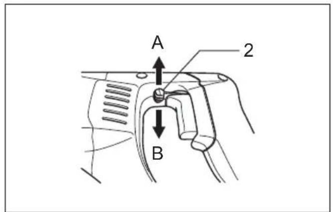
This tool has a reversing switch to change the rotational direction. Move the reversing switch lever to the "A" side for clockwise (forward) rotation or the position "B" side for counterclockwise (reverse) rotation.
CAUTION:
- Always check the rotational direction before operation.
- Use the reversing switch only after the tool comes to a complete stop. It will damage the tool to change the rotational direction before the tool stops.
ASSEMBLY
CAUTION:
• Always be sure that the tool is switched off and unplugged before carrying out any work on the tool.
Installing side grip (auxiliary handle)
CAUTION:
• Always use the side grip and hold it with both hands to ensure operating safety.
Use of it with angle attachment (Fig. 3)
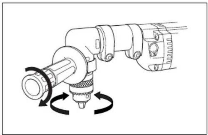
Screw the side grip for the angle attachment on the angle housing. Then tighten the side grip by turning clockwise at the desired position.
Use of it without angle attachment (Fig. 4)
Screw the side grip on the tool barrel securely. The side grip can be installed on either side of the tool, whichever is convenient.
Installing or removing angle attachment
The angle head has a spindle on each end. For higher speed operation, attach the drill chuck to the end marked "HIGH". The higher speed is better suited for drilling smaller diameter holes.
For lower speed operation, attach the drill chuck to the end marked "LOW". The lower speed is best utilized for drilling larger diameter holes. (Fig. 5)
The tool is factory assembled with the chuck on spindle end marked "HIGH". To change to the "LOW" speed, proceed as follows:
To remove the drill chuck, first open the chuck jaws completely and place the chuck key in one of the key holes.
(Fig. 6)
Remove the chuck remaining bolt through the chuck opening by turning it counterclockwise with the hex wrench. (Fig. 7)
CAUTION:
- The drill chuck and the bolt are assembled each other. Turn the bolt counterclockwise about 10 times so that they can be removed together.
Loosen the bolts of the joint by using the hex wrench and remove the angle housing, the joint and the socket. (Fig. 8)
To install the socket and the joint, fit the socket to the spindle so that the two faces are fitted perfectly. Then install the joint. For higher speed operation, fit the angle housing marked "LOW" to the joint. For lower speed operation, fit the angle housing marked "HIGH" to the joint. (Fig. 9)
Rotate the angle housing to the desired position. Tighten the bolt with the hex wrench firmly. And retighten the another bolt firmly again. (Fig. 10)
CAUTION:
- Be sure to tighten the two bolts firmly, or it may present a risk of injury to persons.
Slide the drill chuck to the spindle so that the two faces are fitted perfectly. Holding the drill chuck with the chuck key, tighten the bolt (for installing the drill chuck) clockwise with the hex wrench firmly. (Fig. 11 & 12)
The tool may be converted to a conventional straight drive drill by installing the drill chuck without the angle attachment. (Fig. 13)
Installing or removing drill bit (Fig. 14)
To install the bit, place it in the chuck as far as it will go. Tighten the chuck by hand. Place the chuck key in each of the three holes and tighten clockwise. Be sure to tighten all three chuck holes evenly.
To remove the bit, turn the chuck key counterclockwise in just one hole, then loosen the chuck by hand.
After using the chuck key, be sure to return to the original position.
OPERATION
Holding tool
CAUTION:
- This is a powerful tool. High torque is developed and it is important that the tool should be securely held and properly braced.
Grasp the handle with one hand and the front handle with the other hand. (Fig. 15)
When drilling a large hole with a self-feed bit, etc., the side grip (auxiliary handle) should be used as a brace to maintain safe control of the tool.
When drilling action is forward (clockwise), the tool should be braced to prevent a counterclockwise reaction if the bit should bind. (Fig. 16)
When reversing, brace the tool to prevent a clockwise reaction. If the drill bit must be removed from a partially drilled hole, be sure the tool is properly braced before reversing. (Fig. 17)
Drilling operation
Drilling in wood
When drilling in wood, the best results are obtained with wood drills equipped with a guide screw. The guide screw makes drilling easier by pulling the bit into the workpiece.
Drilling in metal
To prevent the bit from slipping when starting a hole, make an indentation with a center-punch and hammer at the point to be drilled. Place the point of the bit in the indentation and start drilling.
Use a cutting lubricant when drilling metals. The exceptions are iron and brass which should be drilled dry.
CAUTION:
- Pressing excessively on the tool will not speed up the drilling. In fact, this excessive pressure will only serve to damage the tip of your bit, decrease the tool performance and shorten the service life of the tool.
- There is a tremendous twisting force exerted on the tool/bit at the time of hole breakthrough. Hold the tool firmly and exert care when the bit begins to break through the workpiece.
- A stuck bit can be removed simply by setting the reversing switch to reverse rotation in order to back out. However, the tool may back out abruptly if you do not hold it firmly.
- Always secure small workpieces in a vise or similar hold-down device.
- Avoid drilling in material that you suspect contains hidden nails or other things that may cause the bit to bind or break.
MAINTENANCE
CAUTION:
- Always be sure that the tool is switched off and unplugged before attempting to perform inspection or maintenance.
- Never use gasoline, benzine, thinner, alcohol or the like. Discoloration, deformation or cracks may result.
Replacing carbon brushes (Fig. 18 & 19)
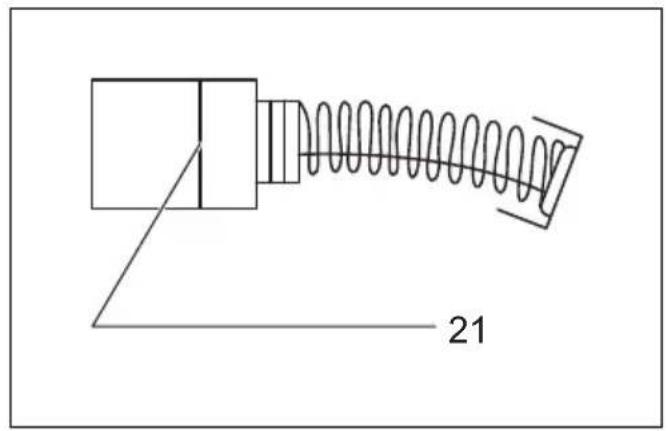
Remove and check the carbon brushes regularly. Replace when they wear down to the limit mark. Keep the carbon brushes clean and free to slip in the holders. Both carbon brushes should be replaced at the same time. Use only identical carbon brushes.
Use a screwdriver to remove the brush holder caps. Take out the worn carbon brushes, insert the new ones and secure the brush holder caps.
To maintain product SAFETY and RELIABILITY, repairs, any other maintenance or adjustment should be performed by Makita Authorized Service Centers, always using Makita replacement parts.
OPTIONAL ACCESSORIES
CAUTION:
• These accessories or attachments are recommended for use with your Makita tool specified in this manual. The use of any other accessories or attachments might present a risk of injury to persons. Only use accessory or attachment for its stated purpose.
If you need any assistance for more details regarding these accessories, ask your local Makita service center.
- Drill bits
- Angle attachment
- Chuck key
- Grip assembly (for angle attachment)
- Side grip
- Extension attachment
- Depth gauge assembly
- Plastic carrying case
NOTE: Some items in the list may be included in the tool package as standard accessories. They may differ from country to country.
Noise
The typical A-weighted noise level determined according to EN62841-2-1:
Sound pressure level (LpA): 83 dB (A)
Sound power level ( LWA ): 91 dB (A)
Uncertainty (K): 3 dB (A)
NOTE:
- The declared noise emission value(s) has been measured in accordance with a standard test method and may be used for comparing one tool with another.
- The declared noise emission value(s) can also be used in a preliminary assessment of exposure.
WARNING:
- Wear ear protection.
- The noise emission during actual use of the power tool can differ from the declared total value(s) depending on the ways in which the tool is used.
- Be sure to identify safety measures to protect the operator that are based on an estimation of exposure in the actual conditions of use (taking account of all parts of the operating cycle such as the times when the tool is switched off and when it is running idle in addition to the trigger time).
Vibration
The continuous vibration total value (tri-axial vector sum) determined according to EN62841-2-1:
Work mode: drilling into metal
Vibration emission (ah, D): 4.6 m/s 2
Uncertainty (K): 2.9 m/s²
NOTE:
- The declared vibration total value(s) has been measured in accordance with a standard test method and may be used for comparing one tool with another.
- The declared vibration total value(s) can also be used in a preliminary assessment of exposure.
WARNING:
- The vibration emission during actual use of the power tool can differ from the declared total value(s) depending on the ways in which the tool is used.
- Be sure to identify safety measures to protect the operator that are based on an estimation of exposure in the actual conditions of use (taking account of all parts of the operating cycle such as the times when the tool is switched off and when it is running idle in addition to the trigger time).
The following shows the mean values of the peak amplitude of the acceleration from repeated shock vibrations, pF , with corresponding uncertainty (K) determined according to EN62841-2-1.
Work mode: drilling into metal
pF : 56 m/s 2
Uncertainty (K): 6 m/s 2
NOTE:
• These declared values should not be used to determine hand arm vibration exposure.
DECLARATIONS OF CONFORMITY
For European countries only
The EU Declaration of Conformity can be accessed from the following URL.

https://support.makita.biz/doc/doc_index.html
For the UK
Annex A to this instruction manual or in digital format using the above URL.
Descriptif
Poids net.... 4,0 kg
DÉCLARATIONS DE CONFORMITÉ
VEILIGHEIDSWAARSCHUWINGEN
GEA010-2
⚠ WAARSCHUWING: Lees alle
OPTIONELE ACCESSOIRES
LET OP:
Sikkerhedsadvarsler for boremaskine
- SPECIFICATIONS
- MODEL DA4000LR
- INTENDED USE
- POWER SUPPLY
- SAFETY WARNINGS
- GENERAL POWER TOOL SAFETY WARNINGS
- DRILL SAFETY WARNINGS
- SAFETY INSTRUCTIONS FOR ALL OPERATIONS
- SAFETY INSTRUCTIONS WHEN USING LONG DRILL BITS
- SAVE THESE INSTRUCTIONS
- WARNING
- FUNCTIONAL DESCRIPTION
- CAUTION
- SWITCH ACTION (FIG. 1)
- REVERSING SWITCH ACTION (FIG. 2)
- ASSEMBLY
- INSTALLING SIDE GRIP (AUXILIARY HANDLE)
- USE OF IT WITH ANGLE ATTACHMENT (FIG. 3)
- USE OF IT WITHOUT ANGLE ATTACHMENT (FIG. 4)
- INSTALLING OR REMOVING ANGLE ATTACHMENT
- (FIG. 6)
- INSTALLING OR REMOVING DRILL BIT (FIG. 14)
- OPERATION
- HOLDING TOOL
- DRILLING OPERATION
- DRILLING IN WOOD
- DRILLING IN METAL
- MAINTENANCE
- REPLACING CARBON BRUSHES (FIG. 18 & 19)
- OPTIONAL ACCESSORIES
- NOISE
- NOTE
- VIBRATION
- DECLARATIONS OF CONFORMITY
- DÉCLARATIONS DE CONFORMITÉ
- VEILIGHEIDSWAARSCHUWINGEN
- OPTIONELE ACCESSOIRES
- LET OP
- SIKKERHEDSADVARSLER FOR BOREMASKINE
Brand : MAKITA
Model : DA4000LR
Category : Drill