
TVIP82000 - Surveillance Camera ABUS - Free user manual and instructions
Find the device manual for free TVIP82000 ABUS in PDF.


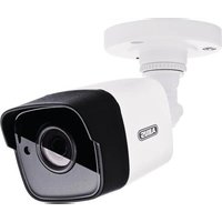
| Product type | IP surveillance camera |
| Brand | ABUS |
| Model | TVIP82000 |
| Maximum resolution | Up to 4K (3840 x 2160) |
| Viewing angle | 100° (horizontal) |
| Night vision | Yes, up to 30 meters |
| Dimensions (L x H x D) | 200 x 80 x 80 mm |
| Weight | 0.5 kg |
| Power supply | PoE (802.3af) or 12 V DC adapter |
| Power consumption | 6 W (max) |
| Connectivity | Ethernet 10/100, Wi-Fi (optional) |
| Supported protocols | IPv4, IPv6, TCP/IP, HTTP, HTTPS, RTSP, ONVIF |
| Local storage | microSD card slot up to 128 GB |
| Cloud storage | Compatible with ABUS Cloud or FTP server |
| Motion detection | Yes, with configurable detection zone |
| Two-way audio | Yes, built-in microphone and speaker |
| Protection rating | IP66 (outdoor) |
| Operating temperature | -20 °C to 50 °C |
| Maintenance and cleaning | Clean with a soft, dry cloth, avoid abrasive products |
| Security | HTTPS encryption, password protection, firmware updates |
| Spare parts and repairability | Not specified |
Frequently Asked Questions - TVIP82000 ABUS
User questions about TVIP82000 ABUS
0 question about this device. Answer the ones you know or ask your own.
Ask a new question about this device
Download the instructions for your Surveillance Camera in PDF format for free! Find your manual TVIP82000 - ABUS and take your electronic device back in hand. On this page are published all the documents necessary for the use of your device. TVIP82000 by ABUS.
USER MANUAL TVIP82000 ABUS
natural_image
Exterior view of a white autonomous security camera with mounted arm and spherical lens (no text or symbols visible)These user manual contains important information for installation and operation. This should be also noted when this product is passed on to a third party. Therefore look after these operating instructions for future reference!
A list of contents with the corresponding page number can be found in the index on page 73.
Français
natural_image
Exterior view of a white security camera with mounted arm and dome (no visible text or symbols)Bedienungsanleitung
Version 05/2013
CE
natural_image
Line drawing of a surveillance camera with lens and control panel (no text or symbols)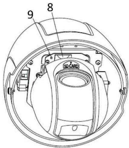
Konto-Informationen hinterlegen:
DynDNS.com
![Add New Hostname Note: You currently don't have any active Dynamic DNS Pro upgrade in your account. You cannot use any features. Paging for any Dynamic DNS Pro upgrade will make the form fully functional and will add severe Hostnames: dvirdns.org software Status: created [compt wifid and support] Service Type: host with IP address (1) Webpage Realmed (5) Offline histrative (1) IP Address: use auto detected IP address 90.76.18.94. STL value in 30 seconds. Call TTR. Mail Roadings: Yes, let me configure Email routing. (2) Add To Cart My Cart Filing My Cart Users](/content/2026/06/1278419/images/63d5c50d58d5f1ac80d8012e5164a38b16dfe203f2955572c03ae7f06b36ebd5.jpg)
Links: hohe Empfindlichkeit.
Aktivierungszeit
Links: hohe Empfindlichkeit.
Aktivierungszeit
natural_image
Exterior view of a white ASUS security camera with mounted arm and dome (no text or symbols visible)User manual
Version 05/2013
CE
Original English user manual. Keep for future use.
Introduction
Dear Customer,
Thank you for purchasing this product.
This device complies with the requirements of the applicable EU directives. The declaration of conformity can be ordered from:
To maintain this condition and to ensure risk-free operation, you as the user must observe these operation instructions!
Before initial start-up, read through the complete operating instructions observing operating and safety instructions.
All company and product names mentioned in this document are registered trademarks. All rights reserved.
If you have any questions, please contact your installer or your local dealer!

Disclaimer
This user manual was prepared with greatest care. If you should notice omissions or inaccuracies, please inform us about these on the back of this manual given address.
The ABUS Security-Center GmbH assumes no liability for technical and typographical faults and reserves the right to make at any time modifications to the product or user manual without a previous announcement.
The company is not liable or responsible for direct and indirect subsequent damages which are caused in connection with the equipment, the performance and the use of this product.
No guarantee for the content of this document is taken.
Icon explanation
 | A flash in the triangle is used if there is danger for the health, e.g. by an electric shock. |
 | An exclamation mark in the triangle points to an important note in this user manual which must be minded. |
 | This symbol can be found when you are to be given tips and information on operation. |
Important safety advice
 | The warranty will expire for damage due to non-compliance with these operating instructions. ABUS will not be liable for any consequential loss! |
 | ABUS will not accept liability for damage to property or personal injury caused by incorrect handling or non-compliance with the safety-instructions.In such cases the warranty will expire. |
The following safety information and hazard notes are not only intended to protect your health, but also to protect the device from damage. Please read the following points carefully:
- There are no components inside the product that require servicing. Dismantling the product invalidates the CE certification and the guarantee / warranty.
- The product may be damaged if it is dropped, even from a low height.
- Install the device so that the image sensor is not subjected to direct sunlight. Pay attention to the installation instructions in the corresponding section of this user guide.
Avoid the following adverse conditions during operation:
- Moisture or excess humidity
• Extreme heat or cold - Direct sunlight
- Dust or flammable gases, vapours, or solvents
• Strong vibrations
• Strong magnetic fields (e.g. next to machines or loudspeakers) - The camera must not be installed on unstable surfaces
General safety information:
- Do not leave packaging material lying around. Plastic bags, sheeting, polystyrene packaging, etc., can pose a danger to children if played with.
- The surveillance camera contains small parts which could be swallowed, and should be kept out of reach of children for safety reasons.
- Do not insert any objects into the device through the openings.
- Only use replacement devices and accessories that are approved by the manufacturer. Do not connect any non-compatible products.
- Please pay attention to the safety information and user guides for the other connected devices.
- Check the device for damage before commissioning. Do not put the device into operation if you detect any damage.
- Adhere to the operating voltage limits specified in the technical data. Higher voltages could destroy the device and pose a health risk (electric shock).
Safety information
- Power supply: power supply unit 100-240 V AC, 50/60 Hz / 24VAC, 3 A (included in the scope of delivery)
Only operate this device on a power source which supplies the power specified on the type plate. If you are unsure which voltage is supplied at the installation location, contact your power supply company. Disconnect the device from the power supply before carrying out maintenance or installation work.
- Overloading
Avoid overloading electrical sockets, extension cables, and adapters, as this can result in fires or electric shocks.
- Cleaning
Only use a damp cloth to clean the device. Do not use corrosive cleaning materials.
Disconnect the device from the power supply while doing so.
Warnings
Observe all safety and operating instructions before putting the device into operation for the first time.
-
Observe the following information to avoid damage to the power cable and plug:
-
Do not modify or manipulate the power cable or plug.
- Do not bend or twist the power cable.
- Do not pull the cable when disconnecting the device from the power – always take hold of the plug.
-
Ensure that the power cable is positioned as far away as possible from any heating equipment, as this could otherwise melt the plastic coating.
-
Follow these instructions. Non-compliance with these instructions could lead to an electric shock.
-
Never open the housing or power supply unit.
- Do not insert any metallic or flammable objects into the device.
-
Use overvoltage protection to prevent damage caused by overvoltage (e.g. electrical storms).
-
Disconnect defective devices from the power immediately and contact your specialist dealer.
| During the installation into an existing video surveillance system make sure that all devices are disconnected from the low and supply voltage circuit. | |
| If in doubt allow a professional electrician to mount, install and wire-up your device. Improper electrical connection to the mains does not only represent at threat to you but also to other persons.Wire-up the entire system making sure that the mains and low voltage circuit remain separated and cannot come into contact with each other in normal use or due to any malfunctioning. |
Unpacking
While you are unpacking the device please handle it with utmost care.
| If you notice any damage of the original packaging, please check at first the device.If the device shows damages, please contact your local dealer. |
Table of contents
- Intended use 75
- Scope of delivery....75
2.1 Indoor domes....75
2.2 Outdoor domes....75
- Features and functions....76
- Device description 76
- Description of the connections 76
- Mounting / installation 76
- Initial start-up....77
- Accessing the network camera for the first time....78
-
Password prompt 79
-
User functions 80
10.1 Menu bar 80
10.2 Live image display 81
10.3 Audio / video control....81
10.4 Camera control 82
10.4.1 PTZ control 82
10.4.2 Preset settings....82
10.4.3 Patrol settings 83
10.4.4 Pattern settings 84
- Configuration....85
11.1 Local configuration....85
11.2 Basic configuration 86
11.3 Advanced Configuration 87
11.3.1 System 87
11.3.1.1 Device Information 88
11.3.1.2 Time Settings 89
11.3.1.3 Maintenance 90
11.3.1.4 RS485....91
11.3.1.5 DST 92
11.3.2 Network....93
11.3.2.1 TCP/IP....94
11.3.2.2 Port 95
11.3.2.3 DDNS....96
11.3.2.4 FTP 99
11.3.2.5 UPnPTM 100
11.3.3 Video / Audio....101
11.3.3.1 Video....102
11.3.3.2 Audio....103
11.3.4 PTZ....104
English
11.3.4.1 Basic1....105
11.3.4.2 Initial Position1 .... 106
11.3.4.3 Park Action....107
11.3.4.4 Privacy Mask....108
11.3.4.5 Scheduled Tasks....109
11.3.4.6 Clear Config....110
11.3.5 Image....111
11.3.5.1 Display Settings....112
11.3.5.2 OSD Settings....115
11.3.5.3 Text Overlay....117
11.3.6 Security ....118
11.3.6.1 Security....118
11.3.6.2 RTSP Authentication....120
11.3.7 Events....120
11.3.7.1 Motion Detection....121
11.3.7.2 Tamper-proof 123
11.3.7.3 Alarm Input 125
11.3.7.4 Alarm Output ....127
11.3.7.5 Email....129
11.3.7.6 Snapshot 131
-
Log.... 132
-
Maintenance and cleaning 132
13.1 Maintenance....132
13.2 Cleaning....132
-
Disposal 133
-
Technical Data 133
-
GPL license information.... 134
1. Intended use
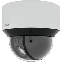
The PTZ network dome camera provides discreet, powerful surveillance. High-resolution images, control options, a high-quality zoom lens, and alarm functions ensure efficient monitoring. The moving 24-hour watchman sets standards: Easily integrated into existing IP networks, it combines the optical precision of a Speed Dome camera with the flexibility and readiness for the future of a network camera.
2. Scope of delivery
2.1 Indoor domes

Day/night PTZ network dome camera with 20x zoom
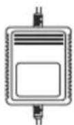
Power supply unit

Adapter panel

Cover panel
Quick guide

Gloves

CD
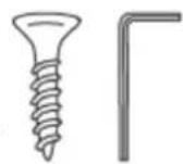
Installation material
2.2 Outdoor domes

natural_image
Line drawing of a surveillance camera with lens and control panel (no text or symbols)Day/night PTZ network outdoor dome camera with 20x zoom

Power supply unit

Adapter

Teflon tape

Quick guide

Gloves

CD

Installation material
3. Features and functions
• Pan/tilt/zoom network camera (PTZ)
• 20x motorized zoom lens
• 8 tours with up to 32 preset positions per tour
- Dual stream: recording in HD, lower resolution for app access
• Good pictures in low light (3D DNR noise reduction)
• Control of the direction of view via network and RS-485
- Privacy masking for hiding of third-party areas
- Watchman and alarm functions (7 alarm inputs and 2 alarm outputs)
- Protection class IP66 and integrated heating (outdoor dome only)
4. Device description
| Model number | TVIP81000 | TVIP81100 | TVIP82000 | TVIP82100 |
| Resolution | 1280 x 720 (720p) | 1920 x 1080 (1080p) | ||
| Outdoor area | √ | √ | ||
5. Description of the connections


| No. | Description |
| 1 | Network cable |
| 2 | Audio |
| 3 | Alarm output |
| 4 | Alarm input |
| 5 | RS-485 |
| 6 | BNC |
| 7 | Power supply |
| 8 | Slot SD card (not used) |
| 9 | Power LED |

Please note that the connections for TVIP81000/TVIP81100/TVIP82000/TVIP82100 are all identical.
6. Mounting / installation
Instructions and installation variants for the network dome cameras can be found in the quick guide
7. Initial start-up
The network camera automatically detects whether a direct connection between the PC and camera should be made. A crossover network cable is not required for this.
Direct connection of the network camera to a PC/laptop
- Ensure that a CAT 5 network cable is used.
- Connect the cable to the Ethernet interface of the PC/laptop and the network camera.
- Connect the power supply to the network camera.
- Configure the network interface of your PC/laptop to the IP address 192.168.0.2 default gateway to 192.168.0.1
- Go to 8, to finish the initial set-up and establish the connection to the network camera.

natural_image
Laptop connected to a security camera via cable (no text or symbols visible)Connecting the network camera to a router/switch
- Ensure that a CAT 5 network cable is used.
- Connect the PC/laptop to the router/switch.
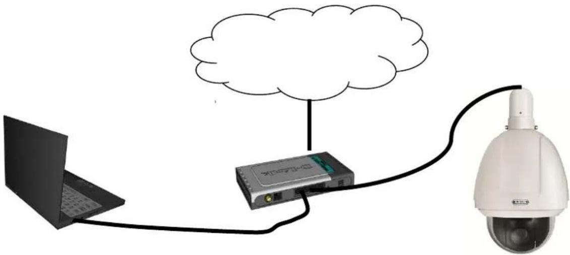
- Connect the network camera to the router/switch.
- Connect the power supply to the network camera.
- If a DHCP server is available in your network, set the network interface of your PC/laptop to "Obtain an IP address automatically".
- If no DHCP server is available, configure the network interface of your PC/laptop to 192.168.0.2 and the default gateway to 192.168.0.1
- Go to point 8 to finish the initial set-up and establish the connection to the network camera.
natural_image
Diagram showing a laptop connected to a security camera via a cloud, with a surveillance camera capturing the device (no text or symbols present)8. Accessing the network camera for the first time
The network camera is accessed for the first time using the IP Installer.
After the installation wizard is started, it searches for all connected ABUS network cameras and video servers in your network.
You can find the program on the included CD-ROM. Install the program on your PC and then run it.
If a DHCP server is available in your network, the IP address is assigned automatically for both the PC/laptop and the network camera.
If no DHCP server is available, the network camera automatically sets the following IP address: 192.168.0.100.
Your PC system must be located in the same IP subnetwork in order to establish communication with the network camera (PC IP address: e.g. 192.168.0.2).


The standard setting for the network camera is "DHCP". If no DHCP server is in operation in your network, then we recommend setting the IP address manually to a fixed value following initial access to the network camera.
9. Password prompt
When delivered, an administrator password is already defined for the network camera. However, the administrator should define a new password immediately for security reasons. After the new administrator password is stored, the network camera asks for the user name and password every time it is accessed.
The administrator account is set up in the factory as follows: User name "admin" and password "12345". Each time the network camera is accessed, the browser displays an authentication window and asks for the user name and password. Should your individual settings for the administrator account no longer be accessible, please contact our technical support team.
To enter a user name and password, proceed as follows:
Open Internet Explorer and enter the IP address for the camera (e.g. "http://192.168.0.14").
You are then prompted for authentication:

-> You are now connected with the network camera and can see a video stream.
10. User functions
Open the main menu on the network camera. The interface is divided into the following main areas:

10.1 Menu bar
Select the appropriate tab: "Live View", "Configuration" or "Log".
| Button | Description |
| admin | Display of the user logged on |
| Abmelden | User logout |
| Sprache | Selection of the desired language |
10.2 Live image display
You can access the full-screen view by double-clicking here.
| Button | Description | ||
 | Activate 4:3 view | ||
 | Activate 16:9 view | ||
 | Display original size | ||
 | Adjust view to browser automatically | ||
 | Stream | Main Stream | Selection of the streaming type for the live cast |
 | Displaying/hiding the camera control | ||
10.3 Audio / video control
| Button | Description |
 | Deactivate live cast |
 | Activate live cast |
 | Deactivate / activate audio, adjust volume |
 | Microphone on / off |
 | Instant image (snapshot) |
 | Start / stop manual recording |
 | Start / stop 3D zoom |
10.4 Camera control
10.4.1 PTZ control
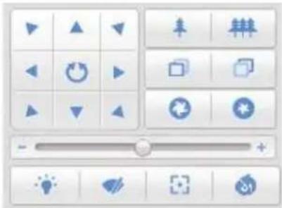
To display the PTZ control, in the live cast click on the field.
| Button | Description | |
 | Arrow buttons:Control of the swivel / inclination motions Start / stop 360° rotation Start / stop 360° rotation | |
 | Zoom in / out | |
 | Close / remote focus | |
 | Light adjustment aperture | |
 | Adjustment of PTZ speed | |
 | Activate IR illuminator (not available) | |
 | Activate wiper (not available) | |
 | One-touch focus (not available) | |
 | Lens initialisation (not available) | |
10.4.2 Preset settings
Select the Preset tab to be able to call up, set and delete up to 256 preset positions. Use the PTZ control buttons to select the desired preset position.
Click on the button to save the preset.
| Button | Description | |
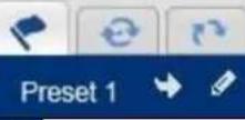 | Selection of the desired preset position. The select preset has a blue background | |
| Call up the position | ||
| Create the position | ||
| Delete the position | ||
Predefined presets:
The following table lists the presets that can only be called and not configured.
| Predefined presets | Function | Predefined presets | Function |
| 33 | Automatic reversal | 93 | Define restrictions manually |
| 34 | Return to initial position | 94 | Remote restart |
| 35 | Call tour 1 | 95 | Call on-screen display menu |
| 36 | Call tour 2 | 96 | Stop scanning |
| 37 | Call tour 3 | 97 | Start random scan |
| 38 | Call tour 4 | 98 | Start frame scan |
| 39 | IR cut filter on | 99 | Start auto scan |
| 40 | IR cut filter off | 100 | Start inclination scan |
| 41 | Call pattern 1 | 101 | Start panorama scan |
| 42 | Call pattern 2 | 102 | Call tour 5 |
| 43 | Call pattern 3 | 103 | Call tour 6 |
| 44 | Call pattern 4 | 104 | Call patrol 7 |
| 92 | Start restrictions | 105 | Call patrol 8 |
10.4.3 Patrol settings
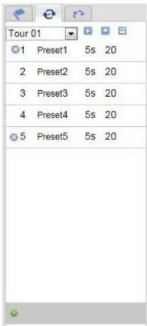
A patrol consists of a series of presets. You can create 8 patrols with up to 32 presets

Please remember that the presets that can be added to a patrol are predefined.
To create a new patrol, proceed as follows:
Select the Patrol tab. Select the desired patrol. To add presets to the patrol, click on the button.
Select the desired preset and set the patrol duration and speed.
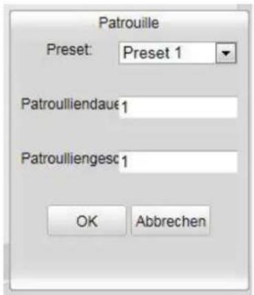
| Patrol Duration | Dwelling time at a preset position. After the time has elapsed the camera switches to the next preset. |
| Patrol Speed | Set the speed of motion to the next preset. |
| Button | Description |
| Selection of the desired pathThe path is reset by clicking on the button for preset 1. | |
| 3 Preset3 5s 20 | Added preset position with path duration and path speed |
| Start path | |
| Stop path | |
| Save path | |
| Delete the preset position, with preset 1 the complete path is deleted |
10.4.4 Pattern settings

A pattern consists of various swivel, inclination and zoom functions. Up to 4 patterns can be set up. To create a pattern, proceed as follows:
Select the patterns tab in the camera control settings.
Select a pattern and activate it with 📄 You can now define the desired route with the arrow keys.
The memory status of the tour is displayed on the screen as follows:

To save the pattern, click on the symbol.
| Button | Description |
| Selection of the desired pattern. This is highlighted in blue. | |
| Start pattern | |
| Stop pattern | |
| Start pattern recording | |
| Stop pattern recording | |
| Delete pattern |
11. Configuration
11.1 Local configuration
Under the "Local Configuration" menu item, you can make settings for the live view, file paths of the recordings and snapshots.

Live View Parameters
Here you can set the protocol type and the live view performance of the camera.
Protocol
TCP: Complete provision of streaming data and high video quality, however this affects real-time transmission
UDP: Real-time audio and video transmission
HTTP: Provides the same quality as TCP, however special ports are not configured under the network settings.
Live View Performance
You can set the performance level for the live view here.
Record File Settings
You can define the file size for recordings, the recording path and the path for downloaded files here. To apply the changes, click "Save".
Record File Size
You can select between 256 MB, 512 MB and 1 GB as the file size for recordings and downloaded videos.
Save record files to
You can determine the file path that is to be used to manual recordings here.
The default path is C:\
Save downloaded files to
You can store the file path for downloaded videos here.
The following path is set by default: C:\
Picture and Clip Settings
Here you can store the path for snapshots taken during playback as well as for video clips.
Save snapshots in live view to
Select the file path for snapshots from the live view.
The following path is set by default: C:\
Save snapshots when playback to
You can store the path here for saving snapshots taken during playback.
The following path is set by default: C:\
Save clips to
You can specify the memory path for storing video clips here.
The following path is set by default: C:\
11.2 Basic configuration
All settings that can be made under "Basic Configuration" can also be found under the menu item "Advanced Configuration". Please take note of the "Available in mode" column in the descriptions of the "Advanced Configuration".

11.3 Advanced Configuration
11.3.1 System

| Menu item | Description | Available in mode |
| Device Information | Display of device information | Basic Configuration, Advanced Configuration |
| Time Settings | Configuration of the time specification | Basic Configuration, Advanced Configuration |
| Maintenance | System maintenance settings | Basic Configuration, Advanced Configuration |
| RS485 | Configuration of the RS485 interface | Advanced Configuration |
| DST (Daylight Saving Time) | Configuration of the automatic daylight savings time switch | Advanced Configuration |
11.3.1.1 Device Information

Basic Information
Device Name
You can specify a device name for the Speed Dome here. Click on "Save" to apply the change.
Model
Model number display
Serial No.
Serial number display
Firmware Version
Firmware version display
Encoding Version
Encoding version display
Number of Channels
Display of the number of channels
Number of Alarm Input
Display of the number of alarm inputs
Number of Alarm Output
Display of the number of alarm outputs
11.3.1.2 Time Settings

Time Zone
Time zone selection (GMT)
Time Sync.
NTP
Using the Network Time Protocol (NTP) it is possible to synchronise the time of the Speed Dome with a time server.
Activate NTP to use this function.
Server Address
IP server address of the NTP server.
NTP Port
Network port number of the NTP service (default: port 123)
Manual Time Sync.
Device Time
Computer device time display
Set Time
Display of the current time using the time zone setting.
Click on "Sync. with computer time" to adopt the device time of the computer.
| Apply the settings made with “Save”. |
Reboot
Click "Reboot" to restart the device.
Default
Restore
Click "Restore" to reset all the parameters to the default settings, with the exception of the IP parameters.
Default
Select this item to reset all parameters to the default values.
Import Config. File
Config. File
Select a file path to import a configuration file here.
Status
Display of the import status
Export Config. File
Click "Export" to export a configuration file.
Remote Upgrade
Firmware
Select the path to update the Speed Dome with new firmware.
Status
Display of the update status

Apply the settings made with "Save".
11.3.1.4 RS485

Baud Rate
You can set the transmission speed using the baud rate. The default setting is 9600 bps. You can select between 2400 bps, 4800 bps, 9600 bps, 19200 bps and 38400 bps.
Data Bit
Setting for the data size for transmissions. You can select between 5, 6, 7 and 8 bits.
Stop Bit
Setting for the stop bit value for the data transmission. You can select either 1 or 2.
Parity
Set the parity to check the error-free transmission of data packages. You can select from the following settings: "None", "Even" and "Odd".
Flow Ctrl.
The flow control is required to transfer information to the Speed Dome that the data transmission is being performed too quickly and data packages are being lost. You can select between: "None", "Hardware" and "Software".
PTZ Protocol
Selection of the protocol for controlling the Speed Dome. You can select between "ABUS", "PELCO D" and "PELCO P".
PTZ Address
Assignment of the Device ID. You can select an ID from between 0 and 255.
| Apply the settings made with “Save”. |
11.3.1.5 DST

DST
Enable DST
Activate the "Enable DST" checkbox to adjust the system time automatically to summer time.
Start Time
Specify the time for switching to summer time.
End Time
Specify the time for switching to winter time.

Apply the settings made with "Save".
11.3.2 Network

| Menu item | Description | Available in mode |
| TCP/IP | Settings of the TCP/IP data | Basic Configuration, Advanced Configuration |
| Port | Settings for the used ports | Basic Configuration, Advanced Configuration |
| DDNS | Settings for the DDNS data | Advanced Configuration |
| FTP | Settings for the FTP data | Advanced Configuration |
| UPnPTM | Settings for the UPnP data | Advanced Configuration |
11.3.2.1 TCP/IP

To be able to operate the Speed Dome via a network, the TCP/IP settings must be configured correctly.
NIC Settings
NIC Type
Select the setting for your network adapter.
You can choose from the following values: 10M Half-dup; 10M Full-dup; 100M Half-dup;
100M Full-dup; 10M/100M/1000M Auto
DHCP
If a DHCP server is available, click DHCP to apply an IP address and other network settings automatically.
The data is transferred automatically from the server and cannot be changed manually.
If no DHCP server is available, please enter the following data manually.
IPv4 Address
Setting for the IP address of the Speed Dome
IPv4 Subnet Mask
Manual setting of the subnet address for the Speed Dome
IPv4 Default Gateway
Setting for the default router for the Speed Dome
MAC Address
The hardware address of the camera is displayed here. You cannot change it.
MTU
Setting for the transmission unit. Select a value between 500 - 9676. 1500 is set by default.
DNS Server
Preferred DNS Server
DNS server settings are required for some applications (for example, sending e-mails). Enter the address of the preferred DNS server here.
Alternate DNS Server
If the preferred DNS server cannot be reached, this alternative DNS server is used. Please store the address of the alternate DNS server here.
| Apply the settings made with “Save”. |
11.3.2.2 Port

If you wish to enable external access to the Speed Dome, the following ports must be configured.
HTTP Port
The standard port for HTTP transmission is 80. As an alternative, this port can be assigned a value in the range of 1024 \~ 65535. If several Speed Domes are connected in the same subnetwork, then each camera should be given a unique HTTP port of its own.
RTSP Port
The standard port for RTSP transmission is 554. As an alternative, this port can be assigned a value in the range of 1024 \~ 65535. If several Speed Domes are connected in the same subnetwork, then each camera should be given a unique RTSP port of its own.
HTTPS port
The standard port for HTTPS transmission is 443.
 | Apply the settings made with “Save”. |
11.3.2.3 DDNS

DynDNS or DDNS (dynamic domain name system entry) is a system that can update domain name entries in real time. The network camera is equipped with an integrated DynDNS client that updates the IP address independently via a DynDNS provider. If the network camera is located behind a router, we recommend using the DynDNS function of the router.
The following diagram offers an overview of accessing and updating the IP address using DynDNS.

flowchart
graph TD
    A["Server"] --> B["Network"]
    B --> C["Cloud"]
    D["Server"] --> C
    style B stroke:#000,stroke-width:2px
    note right of B: ③ DynDNS access data
    note left of B: LAN : WAN
Enable DDNS
Activates or deactivates the DDNS function.
DDNS Type
Select the DDNS type. You can choose between "DynDNS" and "ABUS DDNS".
Server Address
Select a DDNS service provider. You must have registered access to this DDNS service provider (e.g. www.dyndns.org).
If you select "ABUS DDNS" as the DDNS type the server address is stored automatically.
Domains
Enter your registered domain name (host service) here (e.g. myIPcamera.dyndns.org).
Port
Store the port for port forwarding here.
User Name
User ID of your DDNS account
Password
Password of your DDNS account
Confirm
You need to confirm your password here.
Setting up a DDNS account
Set up a new account as follows under DynDNS.org:

Store your account information:

DynDNS.com
![Add New Hostname Add: You currently don't have any active Dynamic DNS Pro upgrade in your account. You cannot use to features. Paying for an Dynamic DNS Pro upgrade will make this form fully functional and will add server Host name: - admin.org Markcard Status: Insured [Start without export] Service Type: Start with IP address (1) Weblog Radford (2) Office Hostname (3) IP Address: Use sure selected IP address 10.75 is all. (1), value is 60 seconds. Edit (1). Mail Settings: Yes, let me configure Email routing. (4) Add To Cart Account Settings Bending My Cart Close](/content/2026/06/1278419/images/627c510fe24a9c2fa4c20e45c3832e0d6f04051489fdffc85d70d94f224383f7.jpg)
Note down your user data and enter this into the configuration of the network camera.
Accessing the network camera over DDNS
If the network camera is located behind a router, then access via DynDNS must be configured in the router. On the ABUS Security-Center homepage www.abus-sc.com, you can find a description of DynDNS router configuration for common router models.
The following diagram offers an overview of accessing a network camera behind a router via DynDNS.org.
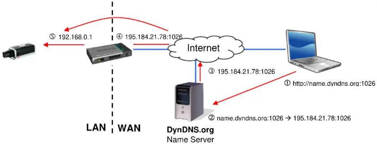
flowchart
graph TD
    A["IP Address"] -->|⑤ 192.168.0.1| B["Server"]
    B -->|④ 195.184.21.78:1026| C["Internet"]
    C -->|③ 195.184.21.78:1026| D["DynDNS.org Name Server"]
    D -->|② name.dyndns.org:1026 → 195.184.21.78:1026| E["Laptop"]
    C -->|① http://name.dyndns.org:1026| F["Computer"]
    style A fill:#f9f,stroke:#333
    style B fill:#ccf,stroke:#333
    style C fill:#cfc,stroke:#333
    style D fill:#fcc,stroke:#333
    style E fill:#cff,stroke:#333
    style F fill:#ffc,stroke:#333

Port forwarding of all relevant ports (at least RTSP + HTTP) must be set up in the router in order to use DynDNS access via the router.
ABUS DDNS

- To be able to use the ABUS DDNS function, you first need to set up an account at www.abus-server.com. Please read the FAQs on this topic on the website.
- Select the "Enable DDNS" checkbox and select "ABUS DDNS" as the DDNS type.
- Apply the data with "Save". The IP address of your Internet connection is now updated every minute on the server.
11.3.2.4 FTP
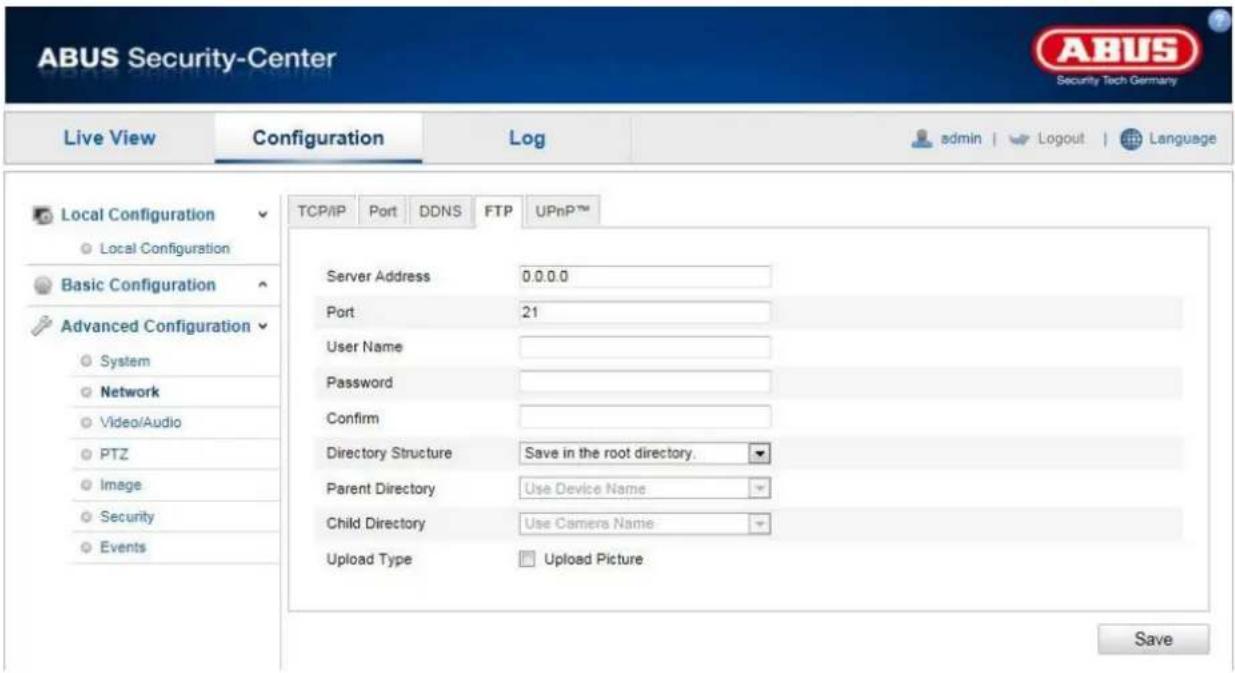
To upload recorded videos or images onto an FTP server, the following settings must be made.
Server Address
Enter the IP address of the FTP server.
Port
Enter the port number of the FTP server. The standard port for FTP servers is 21.
User Name
User name of the account that was configured in the FTP server.
Password
Password of the account that was configured in the FTP server.
Confirm
Reenter the password here.
Directory Structure
Select the storage location for the uploaded data here. You can select between:
"Save in the root directory"; "Save in the parent directory"; "Save in the child directory".
Parent Directory
This menu item is only available if "Save in the parent directory" or "Save in the child directory" was selected under "Directory Structure". You can select the name for the parent directory here. The files are saved in a folder on the FTP server.
Choose between "Use Device Name", "Use Device Number" and "Use Device IP address".
Child Directory
Select the name for the child directory here. The folder is created in the parent directory. You can choose between "Use Camera Name" of "User Camera Number".
Upload Type
Select "Upload Picture" to upload pictures to the FTP server.
| Apply the settings made with “Save”. |
11.3.2.5 UPnP ^TM
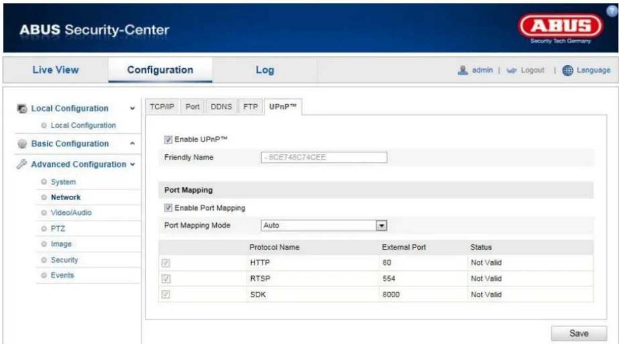
The UPnP (Universal Plug and Play) function makes it easy to control network devices in an IP network. This allows the network camera to be seen in the Windows network environment (e.g. as a network device).
Enable UPnP
For enabling or disabling the UPnP function.
Friendly Name
Display of the MAC address of the camera
Port Mapping
Enable Port Mapping
This enables Universal Plug and Play port forwarding for network services. If your router supports UPnP, then port forwarding for video streams is activated automatically on the router for the network camera using this option.
Port Mapping Mode
Select here whether you wish to conduct port mapping automatically or manually.
You can choose between "Auto" and "Manual".
Protocol Name
HTTP
The standard port for HTTP transmission is 80. As an alternative, this port can be assigned a value in the range of 1025 \~ 65535. If several IP cameras are located on the same subnetwork, then each camera should have its own unique HTTP port.
RTSP
The standard port for RTSP transmission is 554. As an alternative, this port can be assigned a value in the range of 1025 \~ 65535. If several IP cameras are located in the same subnetwork, then each camera should have its own unique RTSP port.
SDK (control port)
The standard port for SDK transmission is 8000. Communication port for internal data. As an alternative, this port can be assigned a value in the range of 1025 \~ 65535. If several IP cameras are located in the same subnetwork, then each camera should have its own unique SDK port.
External Port
You can only change ports manually here of the "Port Mapping Mode" was set to manual.
Status
Displays whether the external port entered is valid or invalid.

Apply the settings made with "Save".
11.3.3 Video / Audio

| Menu item | Description | Available in mode |
| Video | Settings for video output | Basic Configuration, Advanced Configuration |
| Audio | Settings for audio output | Basic Configuration, Advanced Configuration |
11.3.3.1 Video

Stream Type
Select the stream type for the Speed Dome camera. Select "Main Stream (Normal)" for recording and live view with a good bandwidth. Select "Sub Stream" for live view with restricted bandwidth.
Video Type
Select either "Video" or "Video&Audio" for the stream type.

The audio signal is only recorded if you select "Video&Audio" as the stream type.
Resolution
Set the resolution of the video data here. Depending on the camera model you can choose from between 1280*720P; 1280*960; 1920*1080P.
Bitrate Type
Specifies the bit rate of the video stream. The video quality can be higher or lower depending on the intensity of the motions. You can select between a constant and variable bit rate.
Video Quality
This menu item is only available if you have selected a variable bit rate. Set the video quality for video data here. The video quality can differ depending on the intensity of movement. You can select from six different video qualities: "Lowest" "Lower", "Low", "Medium", "Higher" or "Highest".
Frame Rate
Specifies the frame rate in frames per second.
Max. Bitrate
The bit rate of the video stream is set to a certain value. Set a maximum bit rate of between 32 and 16384 Kbps. A higher value means better video quality, however, this requires more bandwidth.
Video Encoding
Select a standard for video encoding. You can choose between H.264, MPEG4 and MJPEG
Profile
Select a profile here. You can choose between "Basic Profile", "Main Profile" and "High Profile".
I Frame Interval
Set the I frame interval here. The value must lie between 1 - 400.
Apply the settings made with "Save".
11.3.3.2 Audio

Select the encoding for audio transmission here.
You can choose between "G.711ulaw", "G.711alaw" and "G.726".

Apply the settings made with "Save".
11.3.4 PTZ

| Menu item | Description | Available in mode |
| Basic | Basic settings for the PTZ function | AdvancedConfiguration |
| Initial Position | Setting the initial position. | AdvancedConfiguration |
| Park Action | Setting for the park action | AdvancedConfiguration |
| Privacy Mask | Definition of privacy zones | AdvancedConfiguration |
| Scheduled Tasks | Definition of scheduled tasks | AdvancedConfiguration |
| Clear Config. | Deletion of PTZ settings | AdvancedConfiguration |
11.3.4.1 Basic1

Basic Parameter
Enable Proportional Pan
Activate this function to adjust the swivel / tilt speed to the respective zoom level. With a high zoom level, the swivel / tilt speed is lower to that the picture does not move too quickly in the live view.
Enable Preset Freezing
If this function is activated, in the live view, the camera switches directly from one scene defined by preset to an other. The areas between are not displayed to ensure monitoring remains efficient. This can reduce broadband usage in the network.

If a pattern is called, preset freezing is deactivated.
Preset Speed
You can select a predefined preset speed of between 1 and 8 here.
Keyboard Control Speed
You can adjust the response speed using the control desk. You can choose between "Low", "Normal" and "High".
Auto Scan Speed
The Speed Dome camera has five different scanning modes: auto scan, tilt scan, frame scan, random scan and panorama scan. A value of between 1 and 40 can be set as the scanning speed.
PTZ OSD
Zoom Status
Set the display duration for the zoom status here. You can select from between 2 seconds, 5 seconds, 10 seconds, "Always Close" and "Always Open".
PT Status
Set the display duration for the azimuth angle during swivelling and tilting here.
You can select from between 2 seconds, 5 seconds, 10 seconds, "Always Close" and "Always Open".
Preset Status
Set the display duration for the preset names when calling a preset position here.
You can select from between 2 seconds, 5 seconds, 10 seconds, "Always Close" and "Always Open".
Power Off Memory
Set Resume Time Point
After a reboot, the camera can resume with the last PTZ status or the last executed action. You can specify the time here after which the resumption of the last action is started. You can select from between 30 seconds, 60 seconds, 300 seconds or 600 seconds.

Apply the settings made with "Save".
11.3.4.2 Initial Position1
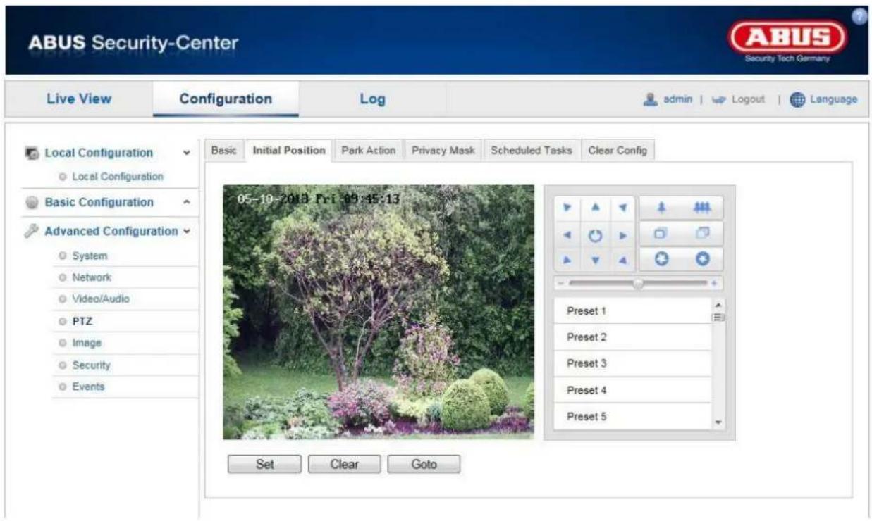
The initial position is the starting point of the PTZ coordinates. This can be both adjusted and changed manually.
To define an initial position manually, proceed as follows. Use the PTZ control buttons to switch to the desired position. You have the option of specifying a previously defined preset position as the initial position.
Click on "Set" to save the position. You can call a predefined initial position using "Goto". To remove an initial position, click on "Clear".
11.3.4.3 Park Action

This function allows you to set the Speed Dome to start a predefined park action (e.g. pattern, patrol, scan, preset, etc.) automatically after a period of inactivity (parking duration).

Please remember that "Scheduled Tasks" have priority over park actions. If both actions are activated, only "Scheduled Tasks" are performed.
Enable Park Action
Enable the function to be able to use the park action.
Park Time
Specify the park time in seconds. You can enter a value between 5 and 720 seconds.
Action Type
Specify here which action is to be started after the park time.
You can select between: "Auto Scan", "Frame Scan", "Random Scan", "Patrol", "Pattern", "Preset", "Panorama Scan" and "Tilt Scan".

Apply the settings made with "Save".
11.3.4.4 Privacy Mask

You can use privacy masks to hide certain areas in the live view to prevent that recording or viewing these areas in the live view is possible.
To set up a privacy mask, proceed as follows: Activate the
"Enable Privacy Masks" checkbox. Use the PTZ control buttons to navigate to the desired position. To add a private zone, click "Draw Area". You can now mark an area on the camera image with your mouse. Afterwards click on "Stop Drawing". By clicking on "Add" you can now change the name and the type of the private zone.
To delete a private zone masking, select the number in the list and click on "Delete".

Apply the settings made with "Save".
11.3.4.5 Scheduled Tasks

Here, you can define a schedule to determine which actions are performed on certain days of the week and at what times.
First activate the "Enable Scheduled Task" checkbox.
Now determine a park time after which the Speed Dome camera is to start a planned task.
Configure the schedule as follows: Click "Edit Tasks".
The following window appears.

Now select a week day for the scheduled task. Select "All Day" if the task is to be executed all day long. To save certain time periods, select "Customize". Enter the start and end times, select a task type and confirm your entry with ENTER.
To apply the configured task for all week days, click the "Select All" checkbox. To copy the task to certain other week days, select the week day and click on "Copy".
To apply the changes, click "OK" and to discard them click on "Cancel".
Please apply the settings made with "Save".
11.3.4.6 Clear Config

In this menu item, you can delete the PTZ configuration including presets, patterns, patrols, privacy masks and scheduled tasks.
Activate the checkbox of the elements you wish to delete. Select "Select All" to delete all of the elements.

Apply the settings made with "Save".
11.3.5 Image

| Menu item | Description | Available in mode |
| Display Settings | Displaying parameter settings | Basic Configuration, Advanced Configuration |
| OSD Settings | Settings for the date and time formats | Advanced Configuration |
| Text Overlay | Adding text fields | Advanced Configuration |
11.3.5.1 Display Settings

You can use this menu item to set the picture quality of the Speed Dome, including brightness, sharpness, contrast and so on. Click on "Default" to restore the default values.

Please note:
The display setting parameters can vary depending on the model.
Brightness
Image brightness settings. A value between 0 and 100 can be set.
Contrast
Image contrast settings. A value between 0 and 100 can be set.
Saturation
Image saturation settings. A value between 0 and 100 can be set.
Limit Gain
Setting for the maximum limit gain. A value between 0 and 100 can be set.
Sharpness
Image sharpness settings. A higher sharpness value can increase image noise.
A value between 0 and 100 can be set.
Focus Mode
For the focus mode, the options "Auto", "Manual" and "Semi-auto" are available.
Auto
The Speed Dome camera focuses automatically depending on the objects in the scene.
Semi-auto
The Sped Dome camera focuses automatically after a swivel, tilt or zoom action.
Manual
The Speed Dome camera has to be focussed manually using the zoom buttons

Minimum Focusing
The minimum focussing distance is defined with this function. The possible values are: 10 cm, 50 cm, 1 m, 1,5 m, 3 m and 6 m. The minimum focus van vary depending on the Speed Dome model.
Exposure Mode
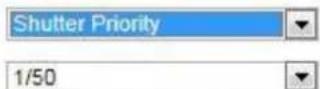
The exposure mode offers the options "Auto", "Iris Priority", "Shutter Priority" and "Manual".
Auto
The values for the aperture, exposure time and gain are automatically adjusted to the ambient brightness.
Manual
In manual, you can set the values for the aperture, exposure time and gain manually. The function may vary depending on Speed Dome model.
Exposure Mode
Iris

Iris Priority
The aperture value must be manually adjusted here. The values for the exposure time and gain are automatically adjusted to the ambient brightness.
Exposure Mode
Iris

Shutter Priority
The exposure time must be manually adjusted here. The values for the aperture and gain are automatically adjusted to the ambient brightness.
Video Standard
Setting for the exposure frequency
50Hz: fixed setting to 50 Hz network frequency
60Hz: fixed setting to 60 Hz network frequency
Day/Night Switch
Day/Night Switch Provides options for "Day", "Night" and "Auto".
Auto
Depending on the light conditions, the camera switches between day and night mode automatically. The sensitivity can be set between "Low", "Normal" and "High".
Exposure Mode
Shutter
Day
In this mode, the camera only outputs colour pictures.

Please note:
Only use this mode if the light conditions remain constant.
Night
In this mode, the camera only outputs black/white and pictures.

Please note:
Only use this mode if the light conditions are poor.
Mirror
If the mirror function is active, the image is mirrored horizontally.
WDR
With the aid of the WDR function, the camera can return clear pictures even in disadvantageous backlight conditions. If there are both very bright and very dark areas in the picture area, the brightness level of the overall picture is balanced to provide a clear, detailed image.
Click on the checkbox to activate or deactivate the WDR function.
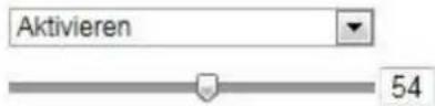
Set the Wide Dynamic Level higher to enhance the WDR function.
WDR
Wide Dynamic Level
Lens Initialization
Activate the checkbox to start an initialization procedure for the lens.
BLC
Objects in front of a bright background can be shown more clearly with the aid of the backlight compensation. The exposure of the objects is corrected, however the background is not shown in focus.
White Balance
Here you select the lighting conditions in which the camera is installed.
You can select between "MWB", "Outdoor", "Indoor", "Florescent Lamp", "Sodium Lamp", "Auto-Track" and "Auto".
MWB
You can adjust the white balance with the following values:
Weißabgleich
Adjusts the white balance to outdoor lighting conditions.
Indoor
Adjusts the white balance to indoor lighting conditions.
Florescent Lamp
Adjusts the white balance to florescent lamp lighting conditions.
Sodium Lamp
Adjusts the white balance to sodium discharge lamp lighting conditions.
Auto-Track
The white balance is continuously and automatically adjusted to the corresponding colour temperature in real time.
Auto
In auto mode, the camera retains the colour balance automatically depending on the current colour temperature.
Digital Noise Reduction
You can activate (normal mode) or deactivate the noise reduction here.
Noise Reduction Level
Set the level for noise reduction here.
Zoom Limit
You can set the maximum zoom level here. The values that can be set are 20, 40, 80, 160 and 320.
Chrome Suppress
Colour suppression for poor light conditions to avoid image noise.
A value between 0 and 100 can be set.
Local Output
Select the output type for local display here. You can choose between the options "Close", "Clip Output" or Scale Output".
11.3.5.2 OSD Settings

You can use this menu item to select which date and time format are displayed in the live picture.
Display Name
Activate this checkbox if you wish to display the camera name.
Display Date
Activate this checkbox if you wish to display the date in the camera image.
Display Week
Activate this checkbox if you wish to display the day of the week.
Camera Name
Enter the camera name that is to be displayed in the image here.
Time Format
Choose here whether you would like to display the time in 24-hour or 12-hour format.
Date Format
Select the format for the date display here.
(M = month; D = day; Y = year)
Display Mode
Here you can select the display mode for the elements displayed.
You have the following options: "Transparent & Flashing", "Transparent & Not flashing", "Not transparent & Flashing", "Not transparent & Not flashing".

Apply the settings made with "Save".
11.3.5.3 Text Overlay

You can display up to four texts in the camera image. The maximum length for the texts is 45 characters. To display the text, activate the checkbox. You can move the text window with the mouse.

Apply the settings made with "Save".
11.3.6 Security
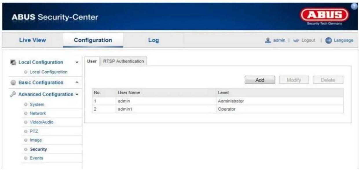
| Menu item | Description | Available in mode |
| User | User administration | Basic Configuration, Advanced Configuration |
| RTSP Authentication | Settings for the date and time formats | Advanced Configuration |
11.3.6.1 Security

With this menu item, you can add, edit or delete users.
To add a user or to edit one, click "Add" or "Modify".
A new window with the data and authorisations appears.

User Name
Here you assign the user name that needs to be entered for access to the camera.
Level
Select an individual user type for the user ID.
You can choose between two predefined levels: "Operator" or "User".
As an operator, the following remote functions are available to you: live view, PTZ control, manual recording, playback, two-way audio, search / query operating status.
As a user, the following remote functions are available to you: playback, search / query operating status.
To add further functions, click the corresponding checkbox.
Password
Here you assign the password that the corresponding user needs to enter for access to the camera.
Confirm
Confirm the password by entering it once more.

Apply the settings made with "Save". Click on "Cancel" to discard the data.
11.3.6.2 RTSP Authentication

You can secure the video stream of the live view.
Select "disable" to deactivate the function. To activate the function, select "basic".

Apply the settings made with "Save".
11.3.7 Events

| Menu item | Description | Available in mode |
| Motion Detection | Settings for motion detection | AdvancedConfiguration |
| Tamper-proof | Setting for the sabotage alarm | AdvancedConfiguration |
| Alarm Input | Setting for the alarm input | AdvancedConfiguration |
| Alarm Output | Setting for the alarm output | AdvancedConfiguration |
| Setting for e-mail dispatch | AdvancedConfiguration | |
| Snapshot | Setting for the snapshot function | AdvancedConfiguration |
11.3.7.1 Motion Detection
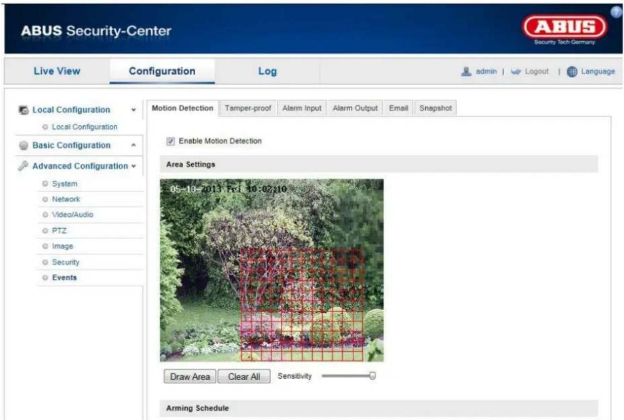
Area Settings
Activate motion detection by clicking the "Enable Motion Detection" checkbox.
To select an area, click on the "Draw Area" button. The entire area is selected by default. To discard this selection, click on "Clear All".
Drag the mouse pointer over the desired area. Set the sensitivity using the regulation control bar. To apply the setting for the area, click on "Stop Drawing".
Right: high sensitivity level
Left: low sensitivity level
Arming Schedule
To save a schedule for motion-controlled recording, click on "Edit".
A new window appears. Specify here on which days of the week and at which times motion-controlled recording should take place.

Now select a week day for motion controlled recording. To store particular time periods, enter a start and end time. To set up all-day motion-detection, select 00:00 as the start time and 24:00 as the end time.
To apply motion detection for all week days, click the "Select All" checkbox. To copy motion detection to other week days, select the week day and click on "Copy".
To apply the changes, click "OK" and to discard them click on "Cancel".
Apply the settings made with "Save".
Linkage Method
Make the setting here for which action motion detection should be performed.
Normal Linkage
Send Email: You receive an e-mail as notification, activate the checkbox for this to be performed.
Upload to FTP: Activate the checkbox to upload the motion-controlled recording to an FTP server.
Other Linkage
You have the opportunity of triggering alarm outputs when motion is detected.
Click on "Select All" to switch on both alarm outputs. To switch on alarm output 1, select "A->1", to switch on alarm output 2, select "A->2".

Apply the settings made with "Save".
11.3.7.2 Tamper-proof

With this menu item you can configure the Speed Dome so that a sabotage alarm is triggered as soon as the lens is covered.
Area Settings
Activate the sabotage alarm by clicking the "Enable Tamper-proof" checkbox.
To select an area, click on the "Draw Area" button. The entire area is selected by default. To discard this selection, click on "Clear All".
Drag the mouse pointer over the desired area. Set the sensitivity using the regulation control bar. To apply the setting for the area, click on "Stop Drawing".
Right: high sensitivity level
Left: low sensitivity level
Arming Schedule
To save a schedule for the sabotage alarm, click on "Edit".
A new window appears. Specify here on which days of the week and at which times the sabotage alarm should be active.

Now select a week day for the sabotage alarm. To store particular time periods, enter a start and end time. To set up an all-day sabotage alarm, select 00:00 as the start time and 24:00 as the end time.
To activate the sabotage alarm for all week days, click the "Select All" checkbox. To copy the sabotage alarm to other week days, select the week day and click on "Copy".
To apply the changes, click "OK" and to discard them click on "Cancel".
Linkage Method
Make the setting here for which action the sabotage alarm should be performed.
Normal Linkage
Send Email: You receive an e-mail as notification, activate the checkbox for this to be performed.
Other Linkage
You have the opportunity of triggering alarm outputs when motion is detected.
Click on "Select All" to switch on both alarm outputs. To switch on alarm output 1, select "A->1", to switch on alarm output 2, select "A->2".

Apply the settings made with "Save".
11.3.7.3 Alarm Input

You can configure the alarm inputs of the Speed Dome with this menu item.
Alarm Input No.
Select the alarm input here that you wish to configure.
Alarm Name
You can specify a device name for the alarm input here. Please do not use the alarm input number or any special characters.
Alarm Type
Select the alarm type here. You can choose between "NO" (normally open) or "NC" (normally closed).
Arming Schedule
To save a schedule for the alarm input, click on "Edit".
A new window appears. Specify here on which days of the week and at which times the alarm input should be active.

Now select a week day for the alarm input. To store particular time periods, enter a start and end time. To activate the alarm input all day, select 00:00 as the start time and 24:00 as the end time.
To apply the settings for all week days, click the "Select All" checkbox. To copy the settings to certain other week days, select the week day and click on "Copy".
To apply the changes, click "OK" and to discard them click on "Cancel".
Linkage Method
Make the setting here for which action motion detection should be performed.
Normal Linkage
Send Email: You receive an e-mail as notification, activate the checkbox for this to be performed.
Upload to FTP: Activate the checkbox to upload the alarm input to an FTP server.
Other Linkage
You have the opportunity of triggering alarm outputs when an alarm is detected.
Click on "Select All" to switch on both alarm outputs. To switch on alarm output 1, select "A->1", to switch on alarm output 2, select "A->2".
PTZ Linking
If an alarm is triggered, you have the option of calling up a preset position, a patrol or a pattern. click the desired checkbox and select the number for the function.
Copy to Alarm
This function allows you to copy the settings of one alarm input to other alarm inputs.
To apply the settings for all alarm inputs, click the "Select All" checkbox. To copy the settings to single alarm inputs, select the alarm input and click on "Copy".

Apply the settings made with "Save".
11.3.7.4 Alarm Output

You can configure the two alarm outputs here.
Alarm Output No.
Select the alarm output here that you wish to configure.
Alarm Name
You can specify a device name for the alarm output here. Please do not use the alarm output number or any special characters.
Arming Schedule
To save a schedule for the alarm output, click on "Edit".
A new window appears. Specify here on which days of the week and at which times the alarm output should be active.

Now select a week day for the alarm output. To store particular time periods, enter a start and end time. To activate the alarm input all day, select 00:00 as the start time and 24:00 as the end time.
To apply the settings for all week days, click the "Select All" checkbox. To copy the settings to certain other week days, select the week day and click on "Copy".
To apply the changes, click "OK" and to discard them click on "Cancel".
Copy to Alarm
This function allows you to copy the settings of one alarm output to other alarm outputs. To apply the settings for all alarm outputs, click the "Select All" checkbox.

Apply the settings made with "Save".
11.3.7.5 Email

You can make the settings for sending e-mails here.
Sender
Sender
Enter a name here that should be displayed as the sender.
Sender's Address
Enter the e-mail address of the sender here.
SMTP Server
Enter the IP address or host name of the SMTP server here. (For example: smtp.googleapis.com)
SMTP Port
Enter the SMTP port here. This is configured as 25 by default.
Enable SSL
Select the SSL function if the SMTP server requires this.
Interval
Set the interval between sending e-mails with picture attachments here.
Attached Image
Enable this function if images are to be attached to the e-mail in the event of an alarm.
Authentication
If the e-mail server in use requires authentication, enable this function to be able to log onto the server with authentication.
User names and passwords can only be entered once this function has been activated.
User Name
Enter the user name of the e-mail account here. This is the part before the @ character.
Password
Enter the password of the e-mail account here.
Confirm
Confirm the password by entering it again.
Receiver
Receiver1 /Receiver2
Enter the user name of the receiver here.
Receiver1's Address / Receiver2's Address
Enter the e-mail address of the person to be informed here.

Apply the settings made with "Save".
11.3.7.6 Snapshot

You can make the configuration for time and event-controlled snapshots here to be able to upload them to an FTP server.
Timing
Enable Timing Snapshot
Enable this function to save pictures at certain intervals.
Format
The format for the pictures is preconfigured as JPEG.
Resolution
Set the resolution of the picture here.
Quality
Select the quality for the saved pictures here.
Interval
Set the interval between saving two pictures here.
Event-Triggered
Enable Event-Triggered Snapshot
Enable this function to enable event-triggered pictures.
Format
The format for the pictures is preconfigured as JPEG.
Resolution
Set the resolution of the picture here.
Quality
Select the quality for the saved pictures here.
Interval
Set the interval between saving two pictures here.
12. Log
Speed Dome parameters such as operation, alarm and exceptions can be saved in the log. The files can be exported if necessary.
- Click on Log in the menu bar to call the search dialog.
- Specify the search criteria including main type, sub-type, start time and end time.
- Click on "Search" to search for log files. The corresponding log files are displayed in the log dialog.
- Click on "Save Log" to export the log files and save them on your computer.
13. Maintenance and cleaning
13.1 Maintenance
Regularly check the product's physical state, e.g. check for damage of the housing.
If you suspect that safe operation cannot be guaranteed anymore, disconnect the product and ensure that it cannot be used by mistake. Remove the batteries.
You can assume that safe operation is not possible anymore when
- the device shows visible damage,
- the device does not function anymore

Please note:
The product is absolutely maintenance-free for you. There are no components on the inside of the product to be checked or services by you, never open it.
13.2 Cleaning
Wipe the product with a clean, dry cloth. If the device is very dirty, you can moisten the cloth with lukewarm water.

Ensure that no liquids can get into the device.
Do not use any chemical cleaners, since they could damage the housing surface or the screen (discolorations).
14. Disposal

Important: The EU Directive 2002/96/EC regulates the proper return, treatment and recycling of used electronic devices. This symbol means that in the interest of environmental protection the device must be disposed of separately from household or industrial waste at the end of its service life in accordance with applicable local legal guidelines. Disposing of used devices can be done at official recycling centers in your country. Obey local regulations when disposing of material. Further details on returns (also for non-European countries) can be obtained at your local authority. Separate collection and recycling saves natural resources and ensures that all the provisions for protecting health and environment are observed when recycling the product.
15. Technical Data
| Model number | TVIP81x00 / TVIP82x00 |
| Image sensor | 1/3" progressive scan CMOS sensor |
| Camera type | Day/night |
| Resolution | 1920 x 1080, 1280 x 960, 1280 x 720, 704 x 576, 352 x 288, 176 x 144 |
| Pixels (total) | 1920 x 1080 (TVIP82x00) / 1280 x 720 (TVIP81x00) |
| Pixels (effective) | 1920 x 1080 |
| Lens | 4.3-86.0 mm |
| Horizontal angle of view | 54.1° - 3.2° |
| Optical zoom | 20x |
| Day/night switching | Electromechanical IR-cut filter |
| Minimum illumination (color) | 0.05 lux |
| Image compression | H.264, MPEG-4, MJPEG |
| Frame rate | |
| H.264: 25 fps @ 1920x1080 | |
| MPEG-4: 25 fps @ 1920x1080 | |
| MJPEG: 25 fps @ 1920x1080 | |
| Number of parallel streams | 4 |
| Electronic shutter control | 1 ~ 1/100000 sec. |
| White balance | Yes |
| Backlight compensation | BLC, WDR |
| Noise reduction | 3D DNR |
| Motion detection | Yes |
| Image overlay | Date, camera name, private zone |
| Alarm input (NO/NC) | 7 |
| Switching output | 2 |
| Alarm notification | E-Mail / FTP / relay output |
| Supported browsers | Mozilla Firefox, Safari, or Internet Explorer 6.x and higher |
| Supported software | ABUS VMS |
| Network access | RJ-45 Ethernet 10/100 Base-T |
| Network protocols | IPv4/IPv6,HTTP,HTTPS,802.1x,Qos,FTP,SMTP,UPnP,SNMP,DNS,DDNS,NTP,RTSP,RTP,TCP,UDP,IGMP,ICMP,DHCP,PPPoE |
| Power supply | 24 V AC |
| Current consumption | Max. 40 W |
| Operating temperature | -30°C – 65°C |
| Dimensions (Hx∅) | 243 x 183.4 mm (TVIP8100, TVIP82000); 325.5 x 220 mm (TVIP81100, TVIP82100) |
| Certifications | CE, RoHS, REACH |
16. GPL license information
Here we wish to inform you that the network surveillance cameras TVIP81000/TVIP81100/TVIP82000/TVIP82100 contain Open Source Software, which is licensed exclusively under the GNU General Public License (GPL). To ensure that your use of the programs conforms with GPL, please refer to the GPL license conditions.
License text
The license text for the GNU General Public License can be viewed on the enclosed software CD or on the ABUS Security-Center homepage at http://www.abus-sc.de/DE/Service-Downloads/Software?q=GPL
Source code
The source code in use can be obtained from ABUS Security-Center upon request if you send an e-mail to license@abus-sc.com up to three years after purchase.
Executability of the overall system
The software packets (source code) do not enable you to set up a functional overall system. You also need a variety of software applications and the hardware developed for the network camera system.
natural_image
Exterior view of a white ABUS security camera with mounted arm and dome (no text or symbols visible)Manuel utilisateur
Version 05/2013
CE
11.3.4.3 Action parking 174
natural_image
Line drawing of a surveillance camera with lens and control panel (no text or symbols)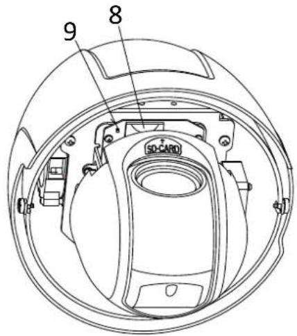
100M Full-dup ; 10M/100M/1000M Auto
DHCP
Activer mapping port
11.3.4.3 Action parking

Activer action parking
natural_image
Exterior view of a white security camera with mounted arm and spherical lens (no text or symbols visible)11.3.3.2 Audio....238
11.3.4 PTZ....239
natural_image
Line drawing of a surveillance camera with lens and control panel (no text or symbols)
100M Full-dup; 10M/100M/1000M Auto
DHCP
Accountgegevens invullen:

DynDNS.com
![Add New Hostname Note: You currently don't have any active Search DNS Pro upgrade in your account. You cannot use to features. Paying for an Dynamic DNS Pro upgrade will make this form fully functional and will add severe Hostname: - search.org Markcard Status: modified (root without support) Service Type: http with IP address: ○ Write up Redoak ○ Office Hostcode IP Address: the auto selected IP address 92.75.16.44 [1] value is 60 seconds [Edit T1] Mail Mountings: Yes, let me configure Email routing. Add To Cart Account Settings siting My Cart None](/content/2026/06/1278419/images/5e2f6086cceaaa787ccc98a80d2c223e652d581a134fe4ba75cb6ec42ad4ec0c.jpg)
Links: hoge gevoeligheid
Activeringstijd
Links: hoge gevoeligheid
Activeringstijd
Timing-snapshot activeren
natural_image
Exterior view of a white security camera with mounted arm and spherical lens (no text or symbols visible)Brugerhåndbog
Version 05/2013
CE
natural_image
Line drawing of a surveillance camera with lens and control panel (no text or symbols)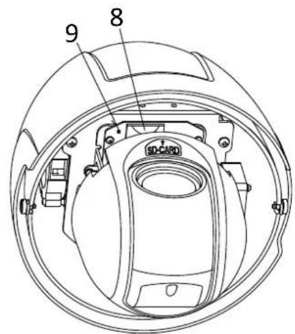
Gem live-snapshot under
natural_image
Exterior view of a white security camera with mounted arm and dome (no visible text or symbols)Instrukcja obsługi
Version 05/2013
CE
11.3.3.2 Audio....371
11.3.4 PTZ....372
natural_image
Line drawing of a surveillance camera with lens and control panel (no text or symbols)
8. Accessing the network camera for the first time
These operating instructions are published by ABUS Security-Center GmbH & Co.KG, Linker Kreuthweg 5, 86444 Affing, Germany. No reproduction (including translation) is permitted in whole or part e.g. photocopy, microfilming or storage in electronic data processing equipment, without the express written consent of the publisher. The operating instructions reflect the current technical specifications at the time of print. We reserve the right to change the technical or physical specifications.
© Copyright 05/2013 by ABUS Security-Center
- Français
- Bedienungsanleitung
- Aktivierungszeit
- Introduction
- Disclaimer
- Icon explanation
- Important safety advice
- The following safety information and hazard notes are not only intended to protect your health, but also to protect the device from damage. Please read the following points carefully:
- Safety information
- Warnings
- Unpacking
- Table of contents
- English
- Intended use
- Scope of delivery
- Indoor domes
- Outdoor domes
- Features and functions
- Device description
- Description of the connections
- Mounting / installation
- Initial start-up
- Direct connection of the network camera to a PC/laptop
- Connecting the network camera to a router/switch
- Accessing the network camera for the first time
- Password prompt
- User functions
- Menu bar
- Live image display
- Audio / video control
- Camera control
- PTZ control
- Preset settings
- Predefined presets:
- Patrol settings
- Pattern settings
- Configuration
- Local configuration
- Live View Parameters
- Protocol
- Live View Performance
- Record File Settings
- Record File Size
- Save record files to
- Save downloaded files to
- Picture and Clip Settings
- Save snapshots in live view to
- Save snapshots when playback to
- Save clips to
- Basic configuration
- Advanced Configuration
- Device Information
- Basic Information
- Device Name
- Model
- Serial No.
- Firmware Version
- Encoding Version
- Number of Channels
- Number of Alarm Input
- Number of Alarm Output
- Time Settings
- Time Zone
- Time Sync.
- NTP
- Server Address
- NTP Port
- Manual Time Sync.
- Device Time
- Set Time
- Reboot
- Default
- Restore
- Import Config. File
- Config. File
- Status
- Export Config. File
- Remote Upgrade
- Firmware
- RS485
- Baud Rate
- Data Bit
- Stop Bit
- Parity
- Flow Ctrl.
- PTZ Protocol
- PTZ Address
- DST
- DST
- Enable DST
- Start Time
- End Time
- Network
- TCP/IP
- NIC Settings
- NIC Type
- DHCP
- IPv4 Address
- IPv4 Subnet Mask
- IPv4 Default Gateway
- MAC Address
- MTU
- DNS Server
- Preferred DNS Server
- Alternate DNS Server
- Port
- HTTP Port
- RTSP Port
- HTTPS port
- DDNS
- Enable DDNS
- DDNS Type
- Domains
- Port
- User Name
- Password
- Confirm
- Setting up a DDNS account
- DynDNS.com
- Accessing the network camera over DDNS
- ABUS DDNS
- FTP
- Directory Structure
- Parent Directory
- Child Directory
- Upload Type
- UPnP TM
- Enable UPnP
- Friendly Name
- Port Mapping
- Enable Port Mapping
- Port Mapping Mode
- Protocol Name
- HTTP
- RTSP
- SDK (control port)
- External Port
- Video / Audio
- Video
- Stream Type
- Video Type
- Resolution
- Bitrate Type
- Video Quality
- Frame Rate
- Max. Bitrate
- Video Encoding
- Profile
- I Frame Interval
- Audio
- Basic1
- Basic Parameter
- Enable Proportional Pan
- Enable Preset Freezing
- Preset Speed
- Keyboard Control Speed
- Auto Scan Speed
- PTZ OSD
- Zoom Status
- PT Status
- Preset Status
- Power Off Memory
- Set Resume Time Point
- Initial Position1
- Park Action
- Enable Park Action
- Park Time
- Action Type
- Privacy Mask
- Scheduled Tasks
- Clear Config
- Image
- Display Settings
- Please note:
- Brightness
- Contrast
- Saturation
- Limit Gain
- Sharpness
- Focus Mode
- Auto
- Semi-auto
- Manual
- Minimum Focusing
- Exposure Mode
- Iris Priority
- Shutter Priority
- Video Standard
- Day/Night Switch
- Day
- Night
- Mirror
- WDR
- Lens Initialization
- BLC
- White Balance
- MWB
- Indoor
- Florescent Lamp
- Sodium Lamp
- Auto-Track
- Digital Noise Reduction
- Noise Reduction Level
- Zoom Limit
- Chrome Suppress
- Local Output
- OSD Settings
- Display Name
- Display Date
- Display Week
- Camera Name
- Time Format
- Date Format
- Display Mode
- Text Overlay
- Security
- Security
- Level
- RTSP Authentication
- Events
- Motion Detection
- Area Settings
- Linkage Method
- Normal Linkage
- Other Linkage
- Tamper-proof
- Arming Schedule
- Alarm Input
- Alarm Input No.
- Alarm Name
- Alarm Type
- PTZ Linking
- Copy to Alarm
- Alarm Output
- Alarm Output No.
- Sender
- Sender's Address
- SMTP Server
- SMTP Port
- Enable SSL
- Interval
- Attached Image
- Authentication
- Receiver
- Receiver1 /Receiver2
- Receiver1's Address / Receiver2's Address
- Snapshot
- Timing
- Enable Timing Snapshot
- Format
- Quality
- Event-Triggered
- Enable Event-Triggered Snapshot
- Log
- Maintenance and cleaning
- Maintenance
- Cleaning
- Disposal
- Technical Data
- GPL license information
- Manuel utilisateur
- Activer mapping port
- Action parking
- Activer action parking
- Activeringstijd
- Timing-snapshot activeren
- Brugerhåndbog
- Gem live-snapshot under
- Instrukcja obsługi
- © Copyright 05/2013 by ABUS Security-Center
Brand : ABUS
Model : TVIP82000
Category : Surveillance Camera