
TVIP71501 - Surveillance Camera ABUS - Free user manual and instructions
Find the device manual for free TVIP71501 ABUS in PDF.


| Product type | IP surveillance camera |
| Brand | ABUS |
| Model | TVIP71501 |
| Dimensions (L x W x H) | Approx. 12 x 7 x 7 cm |
| Weight | Approx. 300 g |
| Power supply | 12 V DC or PoE (Power over Ethernet) |
| Power consumption | Max. 6 W |
| Video resolution | Up to 1920 x 1080 pixels (Full HD) |
| Viewing angle | 90° (horizontal) |
| Night vision | Yes, with infrared LEDs up to 10 meters |
| Motion detection | Yes, built-in |
| Connectivity | Ethernet 10/100, Wi-Fi (depending on version) |
| Storage | microSD card (up to 128 GB), NAS or cloud |
| Audio | Built-in microphone and speaker |
| Protection | IP65 rating (dust and water jet resistant) |
| Operating temperature | -20 °C to +50 °C |
| Maintenance and cleaning | Clean with a soft, dry cloth. Do not use chemical products. |
| Security | SSL/TLS encryption, password-protected access |
| Spare parts and repairability | Contact ABUS after-sales service for parts and repairs. |
| Warranty | 2 years (depending on country) |
Frequently Asked Questions - TVIP71501 ABUS
User questions about TVIP71501 ABUS
0 question about this device. Answer the ones you know or ask your own.
Ask a new question about this device
Download the instructions for your Surveillance Camera in PDF format for free! Find your manual TVIP71501 - ABUS and take your electronic device back in hand. On this page are published all the documents necessary for the use of your device. TVIP71501 by ABUS.
USER MANUAL TVIP71501 ABUS
TVIP71501/TVIP71551/TVIP72500

These user manual contains important information for installation and operation. This should be noted also when this product is passed on to a third party. Therefore look after these operating instructions for future reference!
A list of contents with the corresponding page numbers can be found in the index on page 63.
FR
Bedienungsanleitung
Version 09/2012
CE
4.3 Innenansicht

① Cat5 Ethernetkabel


- VLC Media Player
Real Player - Quicktime Media Player
rtsp://192.168.1.14:554/video.mp4 (MPEG-4 Stream)
rtsp://192.168.1.14:554/video.h264 (H.264 Stream)
Real Player
- Core Player
rtsp://192.168.1.14:554/video.3gp
TVIP71501, TVIP71551: 1280x720, 640x480, 320x240, 160x120
TVIP72500: 1920x1080, 1280x1024, 1280x960, 1280x720, 1024x768,
640x480, 320x240
TVIP71501, TVIP71551: 1280x720, 640x480, 320x240, 160x120
TVIP72500: 1920x1080, 1280x1024, 1280x960, 1280x720, 1024x768,
640×480, 320×240
TVIP71501, TVIP71551: 1280x720, 640x480, 320x240, 160x120
TVIP72500: 1920x1080, 1280x1024, 1280x960, 1280x720, 1024x768,
640x480, 320x240
TVIP71501, TVIP71551: 1280x720, 640x480, 320x240, 160x120
TVIP72500: 1920x1080, 1280x1024, 1280x960, 1280x720, 1024x768,
640x480, 320x240
Standard Router (Gateway)
| 192 | 168 | 0 | 40 |
| 255 | 255 | 255 | 0 |
| 192 | 168 | 0 | 1 |
Konto-Informationen hinterlegen:


* P=PTZ Action, D1/2=Digital Input 1/2, I=IR, F=FTP Upload, S=SMTP notification, H=HTTP notification, N=Network Storage, SD=SD Card
Allgemein
6.10 Systemlog
Aktueller Log
Nov 13 20:55:00 <notice > NET: Starting network...
Nov 13 20:55:00 <notice > NET: MAC = 00.16:FE:00:00:00
Nov 13 20:55:00 <notice > NET: Network type = DHCP
Nov 13 20:55:01 <notice > NET: Host IP = 192.168.0.28
Nov 13 20:55:01 <notice > NET: Subnet Mask = 253.255.0.0
Nov 13 20:55:01 <notice > NET: Gateway = 192.168.0.1
Nov 13 20:55:01 <notice > NET: Primary DNS = 192.168.0.1
Nov 14 08:55:00 <notice > NET: Starting network...
Nov 14 08:55:00 <notice > NET: MAC = 00.16:FE:00:00:00
Nov 14 08:55:00 <notice > NET: Network type = DHCP
Nov 14 08:55:01 <notice > NET: Host IP = 192.168.0.28
Nov 14 08:55:01 <notice > NET: Subnet Mask = 253.255.0.0
Nov 14 08:55:01 <notice > NET: Gateway = 192.168.0.1
Nov 14 08:55:01 <notice > NET: Primary DNS = 192.168.0.1
Nov 14 14:36:52 <notice > syslog: Header Ver : MG01
Nov 14 14:36:52 <notice > syslog: Header Version check Device = MG01
Firmware = MG01
Nov 14 14:36:52 <notice > syslog: Remove
file /mnt/mdb/lang/LNG_TDIF101_MG.0.05.20.v2484_en-US.lang
Nov 14 14:36:52 <err > syslog: FileList: Filename
IR HD 720p/1080p Outdoor Network Dome Camera

UK
User manual
Version 09/2012
CE
Dear Customer,
Thank you for purchasing this product.
This product meets the requirements of the applicable European and national guidelines. The corresponding declarations and documents can be obtained from the manufacturer (www.abus-sc.com).
To maintain this condition and to ensure risk-free operation, you as the user must observe these operation instructions!
Before initial start-up, read through the complete operating instructions observing operating and safety instructions.
All company and product names mentioned in this document are registered trademarks. All rights reserved.
If you have any questions, please contact your installer or your local dealer!

Disclaimer
This user manual was prepared with greatest care. If you should notice omissions or inaccuracies, please inform us about these on the back of this manual given address.
The ABUS Security-Center GmbH & Co. KG assumes no liability for technical and typographical faults and reserves the right to make at any time modifications to the product or user manual without a previous announcement.
The company is not liable or responsible for direct and indirect subsequent damages which are caused in connection with the equipment, the performance and the use of this product.
No guarantee for the content of this document is taken.
Important safety instructions

The warranty will expire for damage due to non-compliance with these operating instructions. We shall not be liable for any consequential loss!

We do not accept liability for damage to property or personal injury caused by incorrect handling or non-compliance with the safety-instructions. In such cases the warranty will expire.
Dear customer,
The following safety instructions are intended not only for the protection of your health, but also for the protection of the device. Please read through the following points carefully:
- There are no parts on the inside of the product which need to be serviced. Apart from this, the license (CE) and the guarantee/warranty will lapse if you open/take the product apart.
• The product will be damaged even it falls from a low height. - This device can be used in inside as well as outside.
- During the installation of the camera please take care that direct sunlight cannot fall onto the image sensor of the device. Please follow the installation instructions in the corresponding chapter of this user manual.
Avoid using the device under the following unfavorable ambient conditions:
- wetness or excessive air humidity
• extreme cold or heat - direct sunlight
- dust or combustible gases, vapors or solvents
• strong vibration
• strong magnetic fields, such as those found in the vicinity of machinery or loudspeakers - the camera should not positioned with opened iris towards the sun - this can lead to the destruction of the sensor.
- the camera may not be installed on unstable surfaces
General safety instructions:
- Do not leave packaging material lying around carelessly. Plastic/foil/bags and polystyrene parts etc. could become dangerous toys for children.
- For safety reasons don't give the camera into child hands due to them being able to swallow small parts.
- Please do not insert objects through the openings into the device.
- Use only accessories which are specified by the manufacturer. Please do not connect incompatible parts to the device.
- Please pay attention to the safety instructions and user manuals of the other connected devices.
- Check the device for damages before installation. If this should be the case please do not use it.
- Please adhere to the operational voltage limitations listed in the technical data. High voltage could destroy the device and pose a health hazard (electric shock).

During the installation into an existing video surveillance system make sure that all devices are disconnected from the low and supply voltage circuit.

If in doubt allow a professional electrician to mount, install and wire-up your device. Improper or make-do electrical connection to the mains does only represent at threat to you but also to other persons.
Wire-up the entire system making sure that the mains and low voltage circuit remain separated and cannot come into contact with each other in normal use or due to any malfunctioning.
Contents
-
Usage in accordance with regulations....65
-
Scope of delivery....65
-
Installation......66
3.1 Power supply 66
3.2 Cable layout 66
3.3 Installing the camera....67
- Camera description....68
4.1 Exterior view 68
4.2 Opening the camera....68
4.3 Interior view 68
4.4 Alarm input and output....69
4.5 Setting the zoom and focus 69
4.6 Using the microSD slot....70
4.7 Status displays 70
4.8 Restoring the factory settings ....70
4.9 Using the analogue video output....71
4.10 Putting into operation....72
4.11 Accessing the network camera for the first time....73
4.12 Accessing the network camera over a web browser....74
4.13 Installing the ActiveX plug-in....74
4.14 Adjusting the security settings....74
4.15 Password prompt....75
4.16 Accessing the network camera over an RTSP player 75
4.17 Accessing the network camera over a mobile phone 76
4.18 Accessing the network camera over ABUS VMS....77
- User functions 78
Video control 80
- Camera settings (configuration)......82
6.1 System....83
6.2 Camera 86
6.3 Playback....90
6.4 Network 93
6.5 Security 101
6.6 Event....104
6.6.1 Event server....104
6.6.2 Event recording....107
6.6.3 Continuous Recording 109
6.7 S witching input and switching output 110
6.8 Motion detection....110
6.9 Schedule....111
6.10 System log 112
7. Maintenance and cleaning....112
7.1 Function test....112
7.2 Cleaning 113
8. Disposal....113
9. Technical data....114
10. GPL license information....116
1. Usage in accordance with regulations

Use of this product for other than the described purpose may lead to damage to the product and other dangers. All other uses are not in accordance with regulations, and result in the invalidation of the product guarantee and warranty. No liability can be accepted as a result. This also applies to any alterations or modifications made to the product.
Read the entire operating manual carefully before putting the product into operation. The operating manual contains important information on installation and operation.
2. Scope of delivery
| ABUS network cameraTVIP71501/TVIP71551/TVIP72500 |  |
| Power supply unit |  |
| Network cable (1 metre) |  |
| Software CD(including operating manual) |  |
| Antenna(TVIP71551) | 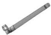 |
| Quick guide |  |
3. Installation
Make sure that all accessories and parts listed above are present in the scope of delivery. An Ethernet cable is required for camera operation. This Ethernet cable must meet UTP Category 5 (CAT 5) specifications and must not be longer than 100 metres.
3.1 Power supply
Before starting installation, ensure that the mains voltage and the rated voltage on the power supply unit are identical.
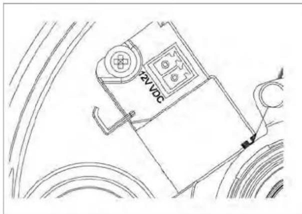
A two-pin plug connection is used for supplying the camera with power. The power supply unit is delivered without the two-pin plug as standard. The plug is already attached to the power supply socket of the camera.
The positive terminal on the power supply unit is marked accordingly. Connect the two wires from the power supply unit (secondary side, 12 VDC) to the power supply plug in the camera.
The plug can be removed from the socket to do this.

3.2 Cable layout
Cables can be laid at the side (visible) or through the bottom (hidden). A cable connection is attached to the housing to protect against moisture. Screw this cable connection fully into the opening on the side or bottom of the housing. The second opening is sealed using the pre-installed plug on the bottom.
3.3 Installing the camera
Firstly, remove the white dome ring by turning it anti-clockwise.
Loosen the three fastening screws on the dome, then remove it.
Three through bores for fastening are found on the outside of the camera base plate.
Hold the base plate as a template on the probable installation site, mark the three fastening holes on the surface, then drill the holes. Use the screws provided to fasten the base plate in place. Cables can be laid at the side or hidden in the ceiling or wall.
The camera module can be tilted and rotated along three axes.
Pan: Rotation of the complete camera module
Tilt: Tilt of the camera module
Rotation: Rotation of the lens with image sensor and IR PCB (third axis)


IMPORTANT!
The camera must be disconnected from the mains power during installation.
4. Camera description
4.1 Exterior view

1 - Cable feed (at side)
2 - Cable feed (hidden in base plate)
3 - Antenna (TVIP71551 only)
4.2 Opening the camera
The camera must be opened to set the angle of view and access the connections inside the camera. Firstly, remove the white dome ring by turning it anti-clockwise. The dome can then be detached after removing the three fastening screws.

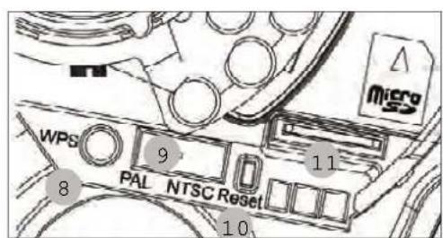
4.3 Interior view

Power supply, polarity
4 – Network connection (Ethernet), RJ45
5 – Power supply, 12 VDC
6 - Analogue video output for service purposes
7 – Alarm input / alarm output
8 - WPS button (for activating the WPS function)
9 - PAL/NTSC switch for analogue video output (4)
10 - Reset button
11 - microSD slot
4.4 Alarm input and output
Adhere to the following connections and maximum loads for the digital alarm input and output.
| Connection | Description Max. load (V/A) | -TZ58 | |
| 12 VDC Voltage output | 12 VDC, max. 100 mA | ||
| GND | Ground connection | ||
| DI – Alarm input Activation of the digital input by connecting the DI and GND connections | - | ||
| DO – Alarm output | Connection of a transistor or relay: Transistor: NPN with emitter against ground (GND)Relay: 12 VDC “and” connection, plus DO with diode (see example below) | 24 VDC, 100 mA | |
Connection example:
![graph TD A["+"] --> B["Power Input"] C["-"] --> B B --> D["DC 12V"] B --> E["GND"] F["12V"] --> G["Switch"] H["GND"] --> G I["DI"] --> G J["DO"] --> G G --> K["SW"] L["Relay"] --> M["Device"] N["Diode"] --> M M --> O["Power Input"]](/content/2026/06/1278414/images/05ad2b95b7f475247b6d462c14848bd7dbc0e5368879e48b0fc4ed520223b6f3.jpg)

Please carefully observe the connection instructions and power specifications!
4.5 Setting the zoom and focus
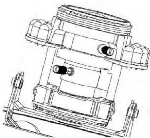
The TVIP71501, TVIP71551 and TVIP72500 camera models are equipped with a variofocal lens. One setting screw for the zoom and one for the focus are found on the bottom of the variofocal lens. These screws are also used for fixing the lens.
Turn the screws carefully anti-clockwise to loosen them. Make the required settings, then fasten both screws again.
| Function Description/option | |
| Zoom setting WIDE – Wide angle of view, 0x zoom (max.) | |
| TELE – Narrow angle of view, 3.3x zoom (max.) | |
| Focus setting FAR – Far focus | |
| NEAR – Near focus | |
4.6 Using the microSD slot

Disconnect the power supply before inserting the microSD
card.
The microSD card can only be inserted into the socket in a specific position. The card protrudes out of the slot by about 4 mm when positioned correctly.
The card is detected by the camera when the power supply is reconnected, and can then be used as desired.


The microSD card cannot be replaced when the system is in
operation!
4.7 Status displays
| LED | Colour | Meaning |
| Network Green Constantly | green when network connection is active | |
| Orange Flashes when network activity is detected (data traffic active) | ||
| Power supply | Red | Constantly red during camera start-up; active for 30 seconds when WPS is active |
| Blue | Constantly blue after successful camera start-up | |
| Violet | Flashes during WPS configuration or firmware update | |
| Off | When reset button is pressed | |
| W-LAN | Green Constantly green when W-LAN connection is active | |
| SD card | Orange Constantly lit when SD card is available | |
4.8 Restoring the factory settings
| Camera restart | Press the button until the blue LED goes out -> constantly red during camera restart -> constantly blue after successful camera restart |
| Restoring the factory settings | Press the button until the LED lights up blue constantly -> constantly blue after successful camera restart |
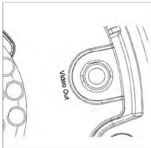
4.9 Using the analogue video output
The analogue video output (Video Out) can be used for connecting an analogue test monitor (and thus, for setting the camera module). The connection is made using a cinch plug.

The analogue video output can be activated or deactivated in the camera configuration. The video option for 640x480 resolution is only available when the analog video output is deactivated.
The analogue video output is activated as standard.
4.10 Putting into operation
The network camera automatically detects whether a direct connection between the PC and camera should be made. A cross-over network cable is not required for this. You can use the supplied patch cable for direct connection when putting into operation for the first time.
Direct connection of the network camera to a PC / laptop
- Ensure that a CAT 5 network cable is used.
- Connect the cable to the Ethernet interface of the PC / laptop and the network camera.
- Connect the power supply to the network camera.
- Configure the network interface of your PC / laptop to the IP address 192.168.1.1 and the default gateway to 192.168.1.2.
- Go to point 4.6 to finish the initial set-up and establish the connection to the network camera.

① CAT 5 Ethernet cable
Connecting the network camera to a router / switch
- Ensure that a CAT 5 network cable is used.
- Connect the PC / laptop to the router / switch.
- Connect the network camera to the router / switch.
- Connect the power supply to the network camera.
- If a DHCP server is available in your network, set the network interface of your PC / laptop to "Obtain an IP address automatically".
- If no DHCP server is available, configure the network interface of your PC / laptop to 192.168.1.1 and the default gateway to 192.168.1.2.
- Go to point 4.6 to finish the initial set-up and establish the connection to the network camera.
8.

4.11 Accessing the network camera for the first time
The network camera is accessed for the first time using the IP Installer.
After the installation wizard is started, it searches for all connected EyseoIP network cameras and video servers in your network.
The program is found on the supplied CD-ROM. Install the program on your PC and then run it.
If a DHCP server is available in your network, the IP address is assigned automatically for both the PC / laptop and the network camera.
If no DHCP server is available, the network camera determines a free IP address from the 192.168.1.2–192.168.1.254 range independently. Your PC system must be located in the same IP segment in order to establish communications with the network camera.


The standard setting for the network camera is "DHCP". If no DHCP server is in operation in your network, then we recommend setting the IP address manually to a fixed value following initial access to the network camera.
4.12 Accessing the network camera over a web browser
When you first access the network camera under Windows, the web browser queries the installation of an ActiveX plug-in for the network camera. This query depends on the Internet security settings of your PC. If the highest security level is set, the PC will refuse any installation and any attempt at running it. This plug-in is used for displaying the video in the browser. To continue, click "Install". If the web browser prevents the installation, open the Internet security settings and reduce the security level or consult your IT or network administrator.
4.13 Installing the ActiveX plug-in

If Mozilla Firefox is used as the browser when accessing the camera, an MJPEG stream is provided by the camera instead of the ActiveX plug-in.
4.14 Adjusting the security settings


Note: Your PC security settings may prevent a video stream. You can change the security settings to a lower level under "Tools / Internet Options / Security". Make sure you enable ActiveX controls and downloads.
4.15 Password prompt
An administrator password is defined in the network camera as standard. However, the administrator should define a new password immediately for security reasons. After the new administrator password is stored, the network camera asks for the user name and password every time it is accessed.
The administrator account is set up in the factory as follows: user name "admin" and password "12345". Each time the network camera is accessed, the browser displays an authentication window and asks for the user name and password. If you can no longer access your personal settings in the administrator account, you can log in again with user name "admin" and password "12345" after resetting the network camera to the factory settings.
To enter a user name and password, proceed as follows:
Open Internet Explorer and enter the IP address of the camera (e.g. "http://192.168.1.14").
You are then prompted for authentication:
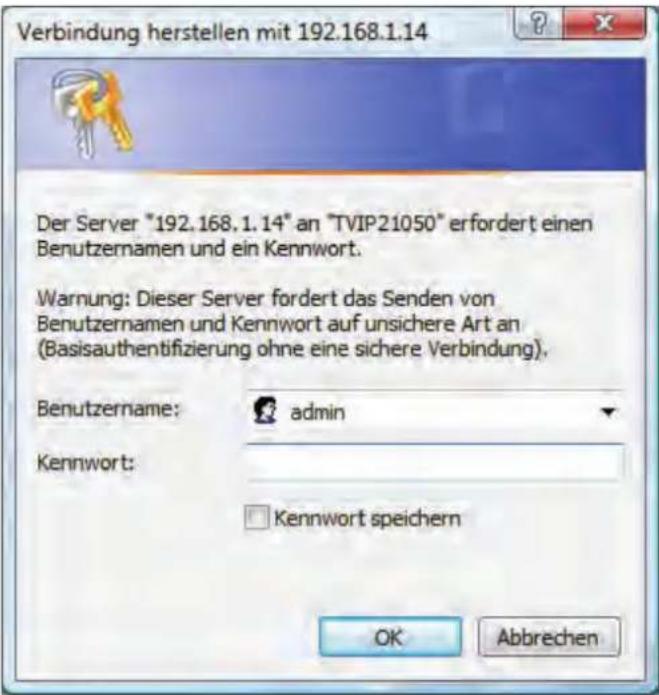
Standard user name: admin
Standard password: 12345
-> You are now connected with the network camera and can see a video stream.
4.16 Accessing the network camera over an RTSP player
You have the possibility of accessing the MPEG-4 / H.264 data streams on the network camera with an RTSP-compatible media player. The following free media players support RTSP:
- VLC Media Player
Real Player - Quicktime Media Player
The address format for entering the connection data is as follows:
rtsp://
Example:
rtsp://192.168.1.14:554/video.mjpg (MJPEG stream)
rtsp://192.168.1.14:554/video.mp4 (MPEG-4 stream)
rtsp://192.168.1.14:554/video.h264 (H.264 stream)
4.17 Accessing the network camera over a mobile phone
Ensure that you can establish an Internet connection over your mobile phone. Your mobile phone must also be equipped with an RTSP-compatible media player. The following media players for mobile phones support RTSP:
- Real Player
- Core Player
Please note that access to the network camera via mobile phone is restricted due to the reduced network bandwidth available. We therefore recommend making the following video stream settings in order to reduce the data quantity:
| Video compression MPEG-4 | |
| Resolution | 160x120 |
| Frame rate 5 frames / second | |
| Video quality (constant bit rate) 48 kbp$ | |
If your media player does not support RTSP authentication, then deactivate the authentication mode for RTSP in the network camera configuration settings.
The address format for entering the connection data is as follows:
rtsp://
Example:
rtsp://192.168.1.14:554/video.3gp
4.18 Accessing the network camera over ABUS VMS
The free 'ABUS VMS Express recording software can be found on the supplied CD-ROM. You then have the possibility of connecting and recording several ABUS Security Center network cameras on one interface. Further information can be found in the software manual on the enclosed CD-ROM.

5. User functions
Open the main menu on the network camera. The interface is divided into the following main areas:

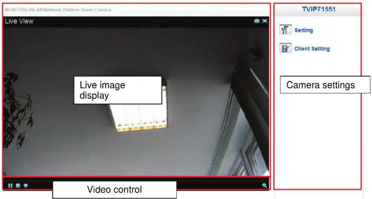
Live image display
You can access the full-screen view by double-clicking here (with Internet Explorer only).
Camera settings

Settings (configuration)
Used to configure the camera (administrator settings)

Live options
Mode: Choose the compression type for transmission of the live image.
View size: Select a view size.
Auto: Automatic adjustment to the screen size
Original size: Display of the video image in accordance with the set camera resolution (e.g. 1920x1080).

Note: The view size specified here relates to the live image shown in the display mode of the browser. The resolution set in the camera is always transmitted, even when the view size set here is smaller.
Protocol: Allows you to select a transmission protocol for data transfer between the client and the server. The following protocol options are available for optimizing the application: UDP, TCP, HTTP.
The UDP protocol gives you a larger number of real-time video streams. However, some data packets can be lost due to the large data volume in the network. Pictures may be unclear in this case. The UDP protocol is recommended if you have no special requirements.
With the TCP protocol, fewer data packets are lost and the video display is more accurate. However, the disadvantage of this protocol is that the video stream is transmitted at a lower frame rate than the UDP protocol.
Use the HTTP protocol if the network is protected by a firewall and only the HTTP port (80) is available.
The selection of the protocol is recommended to be made in the following order: UDP – TCP – HTTP

This function is only available when using Internet Explorer.
Video buffer: Activate the video buffer if your line has low bandwidth. Image data is saved temporarily in the network camera for clearer transmission, meaning the image delay is increased.

This function is only available when using Internet Explorer.
Video control

These functions are only available when using Internet Explorer.

Snapshot
The web browser displays a new window containing the snapshot. To save the snapshot, either left-click it and then click the floppy disk icon or right-click it and select "Save" from the context menu.

Full-screen view
Activate the full-screen view. The live image on the network camera is shown on the entire screen.

Start/stop live image display
The live stream can be stopped or ended. In both cases you can continue the live stream by pressing the play symbol.

Local recording
A recording on the local hard drive can be started or stopped. If you click the button, the Windows "Save as" dialog is called up.

Select a target directory on your hard drive. A directory and recording file are created automatically in the folder under the following name:
YYYYMMDD
YYYYMMDDHHmmss.avi
Y = Year
M = Month
D = Day
H = Hour
m = Minute
s = Second
Example:
C:\Recording\20091215\20091215143010.avi

The recorded data can be played back using an MP4-compatible video player (e.g. VLC Media Player). Alternatively, you can also watch the videos on Windows Media Player by installing a video codec in the IP Installer.

Digital zoom
Click the magnifying glass symbol to activate the digital zoom. The zoom factor can be changed on the scroll bar.

Setting the zoom factor
Change the zoom factor by moving the bar from left (low zoom) to right (high zoom).
6. Camera settings (configuration)
Only the administrator has access to the system configuration. The following sections explain each of the elements in the left-hand column. After you click a menu item on the left-hand side, a menu tree may be opened depending on the number of sub-items contained in the item. In this case, continue by clicking the sub-item.
Click "Home" to return to the main camera page.

Configuration
Home
Setting
System
▶ Camera
▶ Playback
▶ Network
▶ Security
Event
System Log

Welcome to Camera Settings Page
6.1 System
System
Information
Date Time
Initialize
Information
Product information:
Product name: The product name indicates the functions included (e.g. 1080p).
Firmware version: Shows the current version of the installed firmware.
Firmware date: Shows the date of the firmware.
MAC address: Shows the MAC address of the LAN interface.
Date/time: Shows the current date and the time of the camera.
Bandwidth use: Shows the current transmitted data rates from and to the camera (Receive = incoming data rate; Transport = outgoing data rate).
WAN bandwidth use: Shows the current transmitted data rates from and to the camera via the WLAN interface (Receive = incoming data rate; Transport = outgoing data rate) (with TVIP71551 only).
Security
Video connections: Number of users currently logged on (note: connections from recorders or NVRs are also displayed as connections).
User accounts: Number of configured users in the camera
Anonymous access: Indicates whether anonymous users are allowed to view the live image
HTTPS: Information when HTTPS is being used
IP address filter: Information about the activity of the IP filter
Video settings:
Image settings: Information from the image and video settings
Day/night: Information about parameters relating to day/night switching
Event list:
Shows the most recent event triggers (e.g. switching input triggering).
Network:
TCP/IP: IP address and HTTP port currently in use
PPPoE: Information about the use of PPPoE
UPnP: Shows the activity of UPnP
Bonjour: Information about the Bonjour protocol
RTSP: Detailed information about the RTSP ports and RTSP streams in use
Port: Overview of the ports in use. In case of port forwarding, all ports use must be forwarded (at least the HTTP and RTSP port).
Date/time

Current date/time: Shows the setting for the date/time currently stored in the camera.
PC clock: Shows the date/time on the PC from which you access the camera.
Date/time format: Select a format (YYYY-year, MM-month, DD-day, hh-our, mm-minute, ss-second).
Adjust:
Keep current settings: No changes to the settings
Synchronize with the PC: The date and time of the PC are taken over for the camera.
Manual setting: Manually set the time and date here.
Synchronize with the NTP server: Automatic updating of the date and time via a time server (Network Time Protocol)
NTP server name: Enter the domain name of the time server (e.g. de.pool.ntp.org)
Auto: When activated, the standard time server is used. Deactivate the "Auto" setting to enter the NTP server name manually.
Interval: Updating interval with the time server in hours
Time zone: Here you select the time zone in which the camera is located.
Daylight savings time: Enter the dates here for the switch from daylight savings time to standard time.

Accept the settings by pressing "Save" or cancel them by pressing "Cancel".
Initializing
Restart: If you press the button, the camera is restarted.
| Sequencing mode: function is activated. | Restart every x days at the point in time at which the |
| Schedule mode: | Restart on the desired weekday at a certain time. |
Factory settings: Pressing this button causes the factory settings of the camera to be loaded. The selection must be confirmed.
TCP/IP: Check this box to exclude the network setting values from being reset. Date/time: Check this box to exclude the date/time values from being reset.
Save settings: Here you can save a backup file of all camera settings.
Load settings: Settings saved to a backup file can be loaded here.
Update firmware: A more current version of the camera firmware can be loaded here. Information on updated firmware files can be found in the Software section at "http://www.abus-sc.com".
Language
Upload language packet: You can set a different language here by uploading a language file. German is the standard language on the camera upon delivery. The language file for the camera can also be uploaded using the included IP Installer. This can be installed in the appropriate language. Language files for German, English, French, Dutch, and Danish can be downloaded from the Software section at "http://www.abus-sc.com".
6.2 Camera
Camera General H.264 MPEG4 MJPEG 3GPP Advanced
General
Rotate image: Settings for image orientation
Video clip format: Choose between MPEG-4 and H.264 for the compression of the saved video clips (e.g. for sending a video clip via SMTP e-mail). The H.264 option can result in the utilization of more system resources, which can lead to a reduction in camera performance (e.g. frame rate and motion detection).
Flip: The picture is displayed rotated by 180°.
Reverse: The picture is displayed in mirror reverse.
Flip + reverse: Select this option if the camera was installed upside down.
Analog
video output: Activate or deactivate the analog video output on the camera. This video output is used for setting the focus.

The resolution 640x480 is not available and cannot be configured if the analog video output is activated under "Camera / General".
IR Cut Filter Mode: Settings for the swiveled IR-cut filter (ICR)
Auto: The cut filter swivels in or out automatically according to the light sensor. The "Threshold" option specifies the switching values.
Night mode: The swivel filter is constantly separated from the image sensor. The image sensor can record visible light and IR light.
Day mode: The swivel filter is constantly in front of the image sensor. The image sensor can only record visible light.
Schedule: The swivel filter is switched according to a schedule. The "ICR schedule" option appears (for details on configuration, see 6.11, "Schedule").
ICR Cut Filter Switch Delay: Switching from day to night mode can be delayed by up to 10 seconds.
IR Cut Filter Threshold: Bright (H) – The higher the value, the earlier the camera deactivates the IR-cut filter / the IR light.
Dark (L) – The lower the value, the earlier the camera activates the IR-cut filter / the IR light.
IR Mode: Auto: The IR-LEDs are automatically activated or deactivated based on the limits of the threshold value setting.
On: IR-LEDs are constantly activated.
Off: The IR-LEDs are constantly deactivated.
The day/night Dome cameras use two different types of infrared LEDs with different IR angles. The power of both types of LEDs can be separately adjusted.
IR level (Spot): The intensity of the IR LEDs with 30° IR angle can be adjusted from 1% to 100% power.
IR level (Wide): The intensity of the IR LEDs with 60° IR angle can be adjusted from 1% to 100% power.
Host name: Enter the network host name here: the max. length is 32 characters.
Status LED: Switches all status LEDs on the rear on or off.
Text overlay: The setting of the "Title" menu item as well as the date/time can optionally be shown on the video image.
Privacy masking zones: As an alternative to text overlay, one area in the video image can be masked so that it is hidden.

Accept the settings by pressing "SAVE" or cancel them by pressing "Cancel".
H.264
Image size: Select between the following image resolutions (pixels):
TVIP71501, TVIP71551: 1280x720, 640x480, 320x240, 160x120
TVIP72500: 1920x1080, 1280x1024, 1280x960, 1280x720, 1024x768,
640x480, 320x240
Frame rate: Specifies the frame rate in frames per second.
Quality: Setting for the quality of the video stream.
Fixed quality: The video quality is fixed at a certain level. The network bandwidth requirements can rise or fall according to demand.
Fixed bit rate: The bit rate of the video stream is set to a certain fixed value. The video quality can vary according to the level of activity.

Accept the settings by pressing "SAVE" or cancel them by pressing "Cancel".
MPEG-4
Image size: Select between the following image resolutions (pixels):
TVIP71501, TVIP71551: 1280x720, 640x480, 320x240, 160x120
TVIP72500: 1920x1080, 1280x1024, 1280x960, 1280x720, 1024x768,
640x480, 320x240
Frame rate: Specifies the frame rate in frames per second.
Quality: Setting for the quality of the video stream.
Fixed quality: The video quality is fixed at a certain level. The network bandwidth requirements can rise or fall according to demand.
Fixed bit rate: The bit rate of the video stream is set to a certain fixed value. The video quality can vary according to the level of activity.

Accept the settings by pressing "SAVE" or cancel them by pressing "Cancel".
MJPEG
Image size: Select between the following image resolutions (pixels):
TVIP71501, TVIP71551: 1280x720, 640x480, 320x240, 160x120
TVIP72500: 1920x1080, 1280x1024, 1280x960, 1280x720, 1024x768,
640x480, 320x240
Frame rate: Specifies the frame rate in frames per second.
Quality: Setting for the quality of the video stream.
Fixed quality: The video quality is fixed at a certain level. The network bandwidth requirements can rise or fall according to demand.

Accept the settings by pressing "SAVE" or cancel them by pressing "Cancel".
3GPP
Image size: Select between the following image resolutions (pixels):
TVIP71501, TVIP71551: 1280x720, 640x480, 320x240, 160x120
TVIP72500: 1920x1080, 1280x1024, 1280x960, 1280x720, 1024x768,
640x480, 320x240
Frame rate: Specifies the frame rate in frames per second.
Quality: Setting for the quality of the video stream.
Fixed quality: The video quality is fixed at a certain level. The network bandwidth requirements can rise or fall according to demand.
Fixed bit rate: The bit rate of the video stream is set to a certain fixed value. The video quality can vary according to the level of activity.

Accept the settings by pressing "SAVE" or cancel them by pressing "Cancel".
Advanced
Image improvements
Video display: You can call up a preview video by pressing the "Video" button. This is helpful for configuring the following image settings on this page.
Brightness: Image brightness settings
Saturation: Image saturation settings
Contrast: Image contrast settings
Sharpness: Image sharpness settings. A higher sharpness value can increase image noise.
You can reset the four image settings back to the factory settings by pressing the "Standard" button.
White balance
Color hue: You can adjust the basic settings for the color hue here. The colors will be shown warmer or cooler according to the settings.
White balance: Select the corresponding lighting conditions where the cameras are installed.
Exposure settings
Exposure frequency: Auto: Automatic regulation of the exposure frequency
50: Fixed setting at 50 Hz network frequency
60: Fixed setting at 60 Hz network frequency
Fixed: The setting for the exposure frequency is determined and saved when the settings are saved.
Automatic exposure: Specifies the upper limit for automatic exposure.
Slow shutter: On: Setting for a long exposure time in night mode. This results in a brighter
image in case of poor lighting conditions and is accompanied by a lower frame rate.
Off: Setting for a normal exposure time in night mode.
Backlight compensation: When this box is checked, the backlight compensation is activated. When this function is activated, the display of objects in front of bright backgrounds is improved.
Iris-Control
The iris control has influence to the image sharpness. The iris control need to be setup regarding the lens zoom ratio. The following modes are corresponding to the following zoom ratios:
Auto: Lens setting: Zoom ratio low (wide viewing angle)
Offen Lens setting: Zoom ratio mid to max (mid to small viewing angle)
Wide Dynamic Range
Mode: Off: The WDR function is deactivated
Auto: The WDR function is activated.
Level: The dynamic range of the WDR function can be set in 10 levels. The function is automatically controlled up to the maximum set value.
Noise reduction
Mode: Off: The noise reduction function is deactivated.
On: The noise reduction function is continuously activated.
Schedule:
Night mode: The noise reduction function is active when night mode is active.
Schedule:
If the mode is controlled using a schedule, an appropriately configured schedule must be selected here.

Accept the settings by pressing "SAVE" or cancel them by pressing "Cancel".
6.3 Playback
Client PC

Open video file
This button starts the file selection dialog for opening a video file. Playback is then started automatically.

Pause
Pauses the playback of the video file.

Stop
Stops the playback of the video file.

Rewind
Rewinds the video.

Fast-forward
Fast-forwards the video.

Progress bar
Progress bar for playback. Click the bar to jump to a specific point in the video.

Digital zoom
The digital zoom can be activated here. The zoom area can be changed in the video image. The zoom factor can be changed using the "W" (wide angle) and "T" (tele-zoom) buttons.
Network storage
The file manager for data saved on the network is located here (network storage function).
The following buttons have the following functions. Some functions cannot be used until after a file is selected in the "File Name" column; until this happens the button is gray.

Navigate back
Update the current table page
Delete the selected file(s)
Select all files
Play the selected file
Download the selected file (it is only possible to download one file)
SD Card
The file manager for locally saved data is located here (microSD card). It is operated in the same way as the file manager under item "Network storage".
File names / folder names
You can either switch to the current folder path or download the selected file by clicking the respective file/folder names. The data is saved in a folder with the name "IPCamera" along with the MAC address of the camera. The following subfolders are used by the camera.
Event: Storage location of the video data that was recorded due to an alarm event (e.g. motion detection). Schedule: Folder for video data from recordings controlled by a schedule.
All recordings in the main folder are provided with subfolders with the current date (YYYYMMTT and hours (HH)):
Y = Year
M = Month
D = Day
H = Hour
IPCamera001BFE02BF5A/Event/20120425/10/
Example: The "Event" folder for event-controlled recording upon motion detection
| IPCamera001BFE02BF5A/Event/20120425/10/ | ||
| Folder | File Name | Size |
| ../ | ||
| Image-20120425100141_MD.jpg | 36KB | |
| Image-20120425100141_MD_Post01.jpg | 33KB | |
| Image-20120425100141_MD_Pre01.jpg | 34KB | |
| Image-20120425100409_MD.jpg | 33KB | |
| Image-20120425100409_MD_Post01.jpg | 35KB | |
| Image-20120425100409_MD_Pre01.jpg | 36KB | |
| Image-20120425100452_MD.jpg | 33KB | |
| Image-20120425100452_MD_Post01.jpg | 33KB | |
| Image-20120425100452_MD_Pre01.jpg | 34KB | |
| Image-20120425100504_MD.jpg | 33KB | |
| Image-20120425100504_MD_Pre01.jpg | 33KB | |
| Image-20120425100504_MD_Pre01.jpg | 34KB | |
If you click the video file "Intervall_20100511120028.avi", a browser window opens and the file is offered for download or playback is immediately started in the standard media player in Windows. In some browsers these functions are not available; in this case use the buttons for "Playback" and "Download" in the bar over the table with the file names.
6.4 Network
Network
Information
PPPoE
DDNS
RTSP
UPnP
Bonjour
Wireless
WPS
Information
MAC address: The hardware address of the camera is shown here.
Obtain IP address automatically:
The IP address, subnet mask, and address for the default gateway are obtained automatically from a DHCP server. An activated DHCP server must be present in the network in this case.
Use the following IP address:
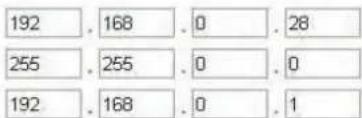
Manual setting of the IP address, subnet mask, and standard router (gateway)
IP address: Manual setting of the IP address for the IP camera
Subnet mask: Manual setting of the subnet address for the IP camera
Standard router (gateway): Manual setting of the standard router for the IP camera
Use the following DNS server address:
If the DNS server address is not automatically assigned by a DHCP server, it can be manually assigned here.
Primary DNS server:
First server address with which the camera attempts to convert DNS names into IP addresses.
Secondary DNS server: Alternative server address with which the camera attempts
to convert DNS names into IP addresses.
HTTP port number:
The standard port for HTTP transmission is 80. As an alternative, this port can be assigned a value in the range of 1024–65535. If several IP cameras are located in the same subnetwork, then each camera should have its own unique HTTP port.
MAC Adresse
00:18 FE 00:00:00
Standard Router (Gateway)
PPPoE: Here you can manually enter the data for your Internet access made available by your ISP (Internet service provider). This is necessary if the IP camera is directly connected to the Internet (without a router).
IP address: The IP address is automatically obtained if the user ID and password of your Internet access is correct and a connection to the ISP exists.
User ID: User ID of your Internet access (up to 64 characters)
Password: Password of your Internet access (up to 32 characters)
Repeat password: You need to confirm your password here.
Automatically obtain a DNS server address: Activate this to automatically determine the DNS server address.
Use the following DNS server address: If the DNS server address is not automatically assigned by your ISP, it can be manually assigned here.
Primary DNS server: First server address with which the camera attempts to convert DNS names into IP addresses.
Secondary DNS server: Alternative server address with which the camera attempts to convert DNS names into IP addresses.

Accept the settings by pressing "SAVE" or cancel them by pressing "Cancel". If the network configuration is changed, then the camera must be restarted (System \ Initialize \ Restart).
DDNS
DynDNS or DDNS (dynamic domain name system entry) is a system that can update domain name entries in real time. The network camera is equipped with an integrated DynDNS client that updates the IP address independently via a DynDNS provider. If the network camera is located behind a router, we recommend using the DynDNS function of the router.
The following diagram offers an overview of accessing and updating the IP address using DynDNS.
![graph TD A["① 192.168.0.3"] --> B["Network"] B --> C["② 195.184.21.78"] B --> D["③ DynDNS access data"] B --> E["Internet"] E --> F["DynDNS.org Name Server"] F --> G["④ 195.184.21.78 → name.dyndns.org"]](/content/2026/06/1278414/images/38f583bec88e73d9072caf698a444efbf75a4e4e94bf36072675769507ce0d6b.jpg)
DDNS: Activates or deactivates the DDNS function.
Server name: Select a DDNS service provider. You must have registered access to this DDNS service provider (e.g. www.dyndns.org).
User ID: User ID of your DDNS account
Password: Password of your DDNS account
Repeat password: You need to confirm your password here.
Host name: Enter your registered domain name (host service) here (e.g. myIPcamera.dyndns.org).
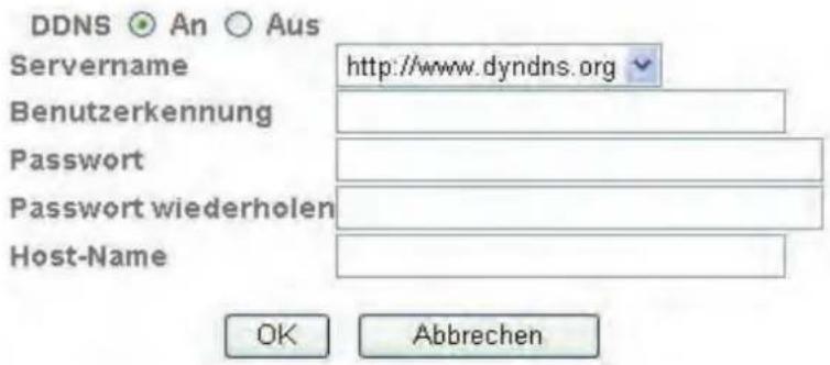
Setting up a DDNS account
Set up a new account as follows under DynDNS.org:
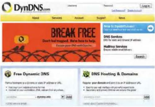
Store your account information:

Note down your user data and enter this into the configuration of the network camera.
Accessing the network camera over DDNS
If the network camera is located behind a router, then access via DynDNS must be configured in the router. On the ABUS Security-Center homepage www.abus-sc.com, you can find a description of DynDNS router configuration for common router models.
The following diagram offers an overview of accessing a network camera behind a router via DynDNS.org.
![graph TD A["Device"] -->|⑤ 192.168.0.1| B["Server"] B --> C["Internet"] C --> D["Laptop"] D -->|① http://name.dyndns.org:1026| E["DynDNS.org Name Server"] E -->|③ 195.184.21.78:1026| C C -->|④ 195.184.21.78:1026| B B -->|LAN WAN| A E -->|nameyddns.org:1026 → 195.184.21.78:1026| C](/content/2026/06/1278414/images/ee1cd20e4cf2f279b252b3e6eb287cc8c1bd67731ffad32e3044940db89938e8.jpg)

Port forwarding of all relevant ports (at least RTSP + HTTP) must be set up in the router in order to use DynDNS access via the router.

Accept the settings by pressing "SAVE" or cancel them by pressing "Cancel". If the network configuration is changed, then the camera must be restarted (System \ Initialize \ Restart).
RTSP
Port range: The standard port range for RTP unicast transmission is 5000–7999. As an alternative, the port range 1024–65534 can be used.
RTSP port: The standard port for RTSP transmission is 554. As an alternative, this port can be assigned a value in the range of 1024–65534. If several IP cameras are located in the same subnetwork, then each camera should have its own unique RTSP port.
Profile name: The access names for the various RTSP streams are configured here. Select the profile to be edited (H.264, MPEG-4, MJPEG, or 3GPP).
Profile: Configuration of the access name for the selected profile.
Authentication: Access to the relevant RTSP stream can be protected with a user name and password.
Examples:
Authentication from: rtsp://192.168.0.100:554/video.h264
Authentication to:rtsp://admin:12345@192.168.0.100:554/video.h264
Multicast:
Multicast designates message transmission from one point to a group (also referred to as a multi-point connection). The advantage of multicast is that messages can be transmitted simultaneously to several recipients or a closed user group without the bandwidth of the sender increasing according to the number of recipients. When using multicast, the sender only requires the same bandwidth as a single recipient. The packets are multiplied on each network distributor (switch, router).
In IP networks, multicast enables efficient sending of data to many recipients at the same time. This is accomplished with a special multicast address. In IPv4, the address range 224.0.0.0 to 239.255.255.255 is reserved for this purpose.
Status: Activated/deactivated
Access name: The access name for RTSP access is configured here.
Multicast address: Entry of the multicast server address
Video port: Automatic or manual assignment of the multicast video port.
Audio port: Automatic or manual assignment of the multicast audio port.
TTL (Time-To-Live): Length of time the packet is kept before being discarded.
UPnP
The UPnP (Universal Plug and Play) function makes it easy to control network devices in an IP network. This allows the network camera to be seen in the Windows network environment (e.g. as a network device).
UPnP: Enable or disable the UPnP function.
Enable UPnP Port forwarding: This enables Universal Plug and Play port forwarding for network services. If your router supports UPnP, then port forwarding for video streams is activated automatically on the router for the network camera using this option.
HTTP port: The standard port for HTTP transmission is 80. As an alternative, this port can be assigned a value in the range of 1024–65535. If several IP cameras are located in the same subnetwork, then each camera should have its own unique HTTP port.
SSL port: The standard port for SSL transmission is 443. As an alternative, this port can be assigned a value in the range of 1024–65535. If several IP cameras are located in the same subnetwork, then each camera should have its own unique SSL port.
RTSP port: The standard port for RTSP transmission is 554. As an alternative, this port can be assigned a value in the range of 1024–65535. If several IP cameras are located in the same subnetwork, then each camera should have its own unique RTSP port.


Accept the settings by pressing "SAVE" or cancel them by pressing "Cancel".
Bonjour
The Bonjour function is a function developed by Apple to make it easier to find network devices in a network. You can find more information about using Bonjour with Windows here:
http://support.apple.com/downloads/Bonjour_for_Windows
Bonjour: Enable or disable the Bonjour function.
Device name: This is the device name displayed in the Bonjour network environment.

Accept the settings by pressing "SAVE" or cancel them by pressing "Cancel".
WLAN antenna (TVIP71551 only)
The camera features a WLAN network interface for wireless data transmission in an IP network. The network camera must be connected via a network cable for the initial configuration of all WLAN parameters.
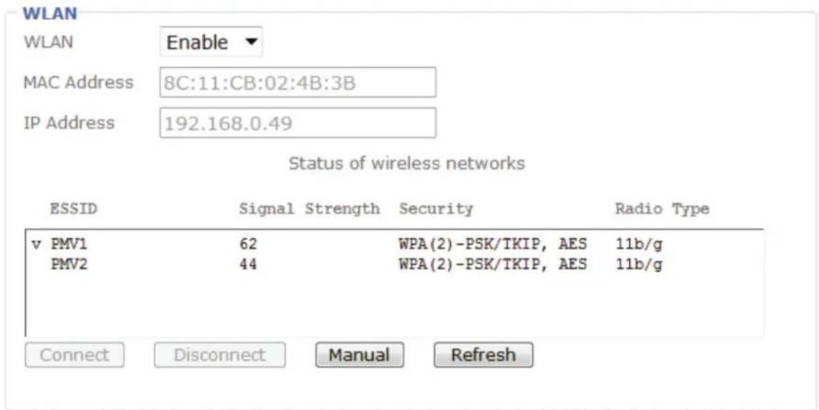
WLAN: Enable or disable the WLAN interface.
MAC address: Shows the MAC address of the wireless interface.
IP address: The set IP address is displayed here. The address can be assigned automatically (DHCP) or manually (see below).
WLAN status display: The camera automatically searches the environment for WLAN access points (APs).
ESSID: Shows the name of the wireless network. If a connection to an access point has been established, this is indicated by the character "v" before the ESSID name.
Signal strength: Shows the signal quality in percent. To ensure a good connection, this value should not be below 60%.
Security: Indicates the way in which the network is protected (encryption type).
Wireless mode: Shows the WLAN standard that the access point (AP) supports.
Connect: When this button is pressed, the software attempts to connect to the selected access point. Additional data important for the connection must be configured in another window (it may be necessary to disable the pop-up blocker). The IP address is automatically determined.
Disconnect: The connection to the selected access point is disconnected.
Manual: Manual configuration of all data required for a wireless connection.
Update: When this button is pressed, the list of available access points is updated.
ESSID: The ESSID is the name of the access point.
Manual setting: Manual setting of the ESSID.
Mode: Select the WLAN connection mode here.
Infrastructure Ad-Hoc The network camera is connected to the network via an access point. In this mode, the network camera can communicate directly with another network adapter (network card). What is known as a peer-to-peer environment is set up.
Authentication: Here you can set the encryption mode for the wireless transmission.
Open No encryption selected.
Common key (WEP, Wired Equivalent Privacy) A 64- or 128-bit key is used for encryption (HEX or ASCII). For communication with other equipment, these keys must be the same on both devices.
(10/26 HEX characters or 5/13 ASCII characters according to bit length)
WPA-PSK/WPA2-PSK (Wi-Fi Protected Access – Pre-Shared Keys) With this method, dynamic keys are used. TKIP (Temporal Key Integrity Protocol) or AES (Advanced Encryption Standard) can be selected as the encryption protocols. What is known as a passphrase (pre-shared key) must be assigned as the key. (64 HEX characters or 8 to 63 ASCII characters)
Encryption: Select the corresponding type of encryption here. Common key: WEP / disabled WPA-PSK / WPA2-PSK: TKIP or AES
Key length: With WEP only. Select the bit length for the key here.
Network key: With WEP only. Up to four keys can be assigned.
Obtain IP address automatically: The IP address, subnet mask, and address for the default gateway are obtained automatically from a DHCP server. An activated DHCP server must be present in the network in this case.
Use the following IP address:
Manual setting of the IP address, subnet mask, and standard router (gateway)
Use the following DNS server address:
If the DNS server address is not automatically assigned by a DHCP server, it can be manually assigned here.
Primary DNS server:
First server address with which the camera attempts to convert DNS names into IP addresses.
Secondary DNS server: Alternative server address with which the camera attempts to convert DNS names into IP addresses.

Accept the settings by pressing "SAVE" or cancel them by pressing "Cancel".
WPS (TVIP71551 only)
WPS (Wi-Fi Protected Setup) is a simple method for establishing a secure wireless network connection (WPA, WPA2). Consult the manual for your access point (e.g. router with WPS function) regarding the necessary steps for setting up the WPS function.
WPS: Enable the WPS function here if required.
MAC address: Shows the MAC address of the wireless interface.
IP address: The set IP address is displayed here. The address can be assigned automatically (DHCP) or manually (see below).
Configure via: PBC:
Push Button Configuration – You set up a secure wireless connection by pressing the button on the access point or network camera.
PIN:
A secure wireless connection is set up in the network camera and access point through the assignment of a PIN. Press the "Generate new PIN" button to assign a new random PIN. This PIN must then be made known in the access point (WPS settings). Press "Start". The network camera and access point are then automatically connected to each other via a secure connection.
Connect: A connection is established via WPS with the selected procedure (PBC or PIN).
Disconnect: The connection is disconnected.
Update: The list of available access points supporting WPS is updated.
6.5 Security

User
This menu item describes the user administration of the network camera. Up to 10 user accounts can be defined. The user accounts can each have one of three user types.
User list: Shows all configured users with the corresponding authorization levels.
Add: Add a user account.
Edit: Edit an existing user account. Before doing this, you need to select the required user account from the list.
Delete: Delete a user account.
| User types Permissions | |
| Administrator | Full access, including live views, configuration |
| Operator | Live view |
| Viewer | Live view |
The default access data for the main administrator is as follows:
User name: "admin"
Password: "12345"
User name: Here you assign the user name that needs to be entered for access to the camera.
Password: Here you assign the user name that needs to be entered for access to the camera.
Repeat entry: Here you assign the password that the corresponding user needs to enter for access to the camera.
User type: Select an individual user type for the user ID.
Anonymous setting: Activated Anonymous setting allows any user to see the main page including video stream. All settings pages are still password protected.

Accept the settings by pressing "SAVE" or cancel them by pressing "Cancel".
HTTPS
The HTTPS protocol is used for encryption and for authenticating communication between the web server (network camera) and browser (client PC) on the Internet. All data transmitted between the network camera and client PC is encrypted using SSL. Apart from SSL encryption (compatible with all standard browsers), a source authorization certificate is required in order to use HTTPS.

Create a self-signed certificate: You can use this button to create a self-signed certificate.
Country: Country specification in 2-character code (e.g. DE)
State or province: Max. length of 32 characters (A-z, A-Z, 0-9)
City: Max. length of 32 characters (A-z, A-Z, 0-9)
Organization: Max. length of 32 characters (A-z, A-Z, 0-9)
Department: Max. length of 32 characters (A-z, A-Z, 0-9)
Registered name: Max. length of 32 characters (A-z, A-Z, 0-9)
Duration of validity: Enter how long this certificate will remain valid here (0–1000).
Note: When using a "self-signed certificate", you may receive a warning message from your browser. Self-signed certificates are always classified as insecure by the browser as the source certificate and authorization of the certification authority are both absent.

Accept the settings by pressing "SAVE" or cancel them by pressing "Cancel".
IP filter
Specific IP areas can be authorized or blocked for camera access in this configuration menu:
IP filter: Enable or disable the IP filter function.
Filter list:
Filter type:
List of all filters that have been set up as well as buttons for editing the filters.
Preselection of whether a filter should permit or block before it is defined using the "Add" button.
Add: Add a filter.
Edit: Edit a selected filter.
Delete: Delete a selected filter.
Rule: Individual IP: Definition of a filter for an IP address.
Network: Definition of a filter for a certain network.
Range: Definition of a filter for a certain IP address range.

The IP filter function is only enabled with user type “Operator” or “Viewer”. A user with the “Administrator” user type always has access to the network camera.

Accept the settings by pressing "SAVE" or cancel them by pressing "Cancel".
6.6 Event
What are known as actions (e.g. sending of an e-mail with an image upon motion detection) are generally configured as follows:
Event-controlled recording:
![graph LR A["Configuration of the trigger (e.g. switching input)"] --> B["Storage server (FTP, SMTP, SD card, ...)"] B --> C["Media settings"] C --> D["Event configuration"]](/content/2026/06/1278414/images/3514ccbf893a31b50c28fd2d811ad8045d8265ede62ce74a59d8eefc41b1e700.jpg)
Scheduled recording:
A scheduled recording can only be made with video files.
![graph LR A["Schedule"] --> B["Storage server (FTP, SMTP, SD card, ...)"] B --> C["Scheduled recording (video files only)"]](/content/2026/06/1278414/images/caef5b3138181de35d9d6ac4dab78bcb9837bb98bf0a460d1bb3202be3b44c6a.jpg)
6.6.1 Event server
All configured event servers are shown in a list here.
Name: Name used for the event server
Protocol: Protocol used for the event server
Network address: Network address / target address of the event server
Add: Add an event server
Edit: Edit an event server entry
Delete: Delete an event server entry
General
Name: Enter a name for the server here.
Server settings
Use the selection box to select a server type.
FTP:
Network address: Enter the IP address or domain name of the FTP server here. The maximum length is 64 characters.
Server port: Enter the port number of the FTP server. The standard port for FTP servers is 21.
Server path: This is the file folder in which the data on the FTP server is saved. The maximum length is 64 characters.
User name: User name of the account that was configured in the FTP server.
Password: Password of the account that was configured in the FTP server.
Repeat password: Reenter the password here.
| Passive mode: | Enable this function if the FTP server was configured in passive mode. |
| Test: | When this button is pressed, the FTP server settings are tested. A test file is uploaded to the FTP server |
SMTP:
| SMTP server address: | Enter the address of the outgoing e-mail server here (SMTP server). |
| Server port: | The standard SMTP server port is 25. An alternative port can be assigned if required. |
| SSL: If the e-mail server uses SSL, it can be enabled here. | |
| Authentication: Define the authentication type for the e-mail account here. | |
| SMTP: | If authentication on the e-mail server requires a user name and password, this option must be enabled. |
| POP before SMTP: | Select this option if e-mails must be retrieved before e-mails can be sent. It may be possible to delete “POP before SMTP” in the e-mail account settings. |
| E-mail sender: This is the address of the e-mail account. The maximum length is 64 characters. | |
| E-mail recipient: The e-mail address of the recipient. The maximum length is 64 characters. | |
| Test: | When this button is pressed, the SMTP server settings are tested. A test file is sent to the e-mail recipient. |
HTTP:
Use this function to save image data (individual images) on an HTTP server. A CGI script on the HTTP server must be able to receive the data. In the event of questions, please contact your network administrator.
URL: Enter the URL of the HTTP server (e.g. "192.168.0.156/cgi-bin/webcam").
Port: Enter the port on which the HTTP server operates.
User ID: User ID on the HTTP server
Password: Password on the HTTP server
Repeat password: Reenter the password here.
Proxy address: Server name when a proxy server is used
Proxy port number: Port number of the proxy server
Proxy user name: User ID on the proxy server
Proxy password: Password on the proxy server
Test: When this button is pressed, the HTTP server settings are tested. A test file is sent to the HTTP server.
Network drive:
Type: Protocol selection between the Windows network (SMB/CIFS) or UNIX network (NFS)
Windows network (SMB/CIFS)
Network storage capacity: Entry of the IP or drive/folder of the network drive
Ex.: \IP\Folder
Ex.: \my_nas:\Folder name
Workgroup: Workgroup of the Windows network drive
User name: User name of the workgroup.
Password: Password of the workgroup.
Repeat password: Reenter the password for the workgroup here.
Create folder: An additional subfolder is created on the network drive.
Test: When this button is pressed, the network drive settings are tested. A test file is sent to the network drive.
Unix network drive (NFS):
Network storage capacity: Entry of the IP or drive/folder of the network drive
Ex.: my_nas:\Folder name
Create folder: An additional subfolder is created on the network drive.
Test: When this button is pressed, the network drive settings are tested. A test file is sent to the network drive.
Media settings
File attachment: Here you select a file type for the file attachment.
Snapshot: The file attachment is individual images in JPEG format.
Video: The file attachment is video files in MP4 format.
System log: The log file is sent as the medium.
Snapshot
Send pre-alarm image(s): Enter the required number of pre-alarm images (number 0–7).
Send post-alarm image(s): Enter the required number of post-alarm images (number 0–7).
File name: Assign a file name if required.
Suffix: None: No suffix is added to the file name.
Date/time: The date and time is added to the file name.
Sequence number: A sequence number is added to the file name.
Delete sequence number: When the button is pressed, the sequence number is reset.
Video
Pre-alarm recording: Enter a pre-alarm recording time (0–7 seconds).
Post-alarm recording: Enter a post-alarm recording time (1–7 seconds).
File name: Assign a file name if required.
System log
File name: Assign a file name if required.
SD card
SD card: Enable or disable the SD card function. An SD card must be inserted for this. The SD card must be inserted when the power is off.
When the SD card function is enabled, the SD card user interface changes.
Format: Press this button to format the SD card.
SD card status:
Shows the free storage capacity and size of the memory card in KB.
30023904/31519696 KB
Create folder: Another subfolder for storage can be created on the SD card.
Overwrite: When this function is enabled, all data is overwritten when the maximum SD card capacity is reached.
Storage space warning: The storage space warning function can be used as a triggering event for event actions. If the free storage space falls below a certain value (5%, 10%, 25%, 50% free storage space), the event is triggered.
Media settings
The possible settings are the same as the settings under item "Event server list / Media settings".
6.6.2 Event recording
The events list contains all configured event actions.
Name: Name of the configured event
Enabled: Shows whether the event is enabled.
Trigger: Information about the trigger used for the event action
Action: Information about the action that follows after the event is triggered
* P=PTZ Action, D1/2=Digital Input 1/2, I=IR, F=FTP Upload, S=SMTP notification, H=HTTP notification, N=Network Storage, SD=SD Card
Schedule: Schedule of the event action
Priority: The camera processes event actions in the order in which they occur. The priority setting allows certain events to receive priority treatment.

Add: Add an event action to the event list (-> event configuration).
Edit: Edit a configured event action.
Delete: Delete an event action.
Event configuration
General
Name: Assign a name to the event action.
Event: Enable or disable the event.
Trigger
Triggered by: The following options are available as triggers:
Motion detection:
Switching input:
Interval process
Upon restart:
ICR filter:
Storage space warning:
Network connection inactive:
IP notification:
The configuration of the various triggering events are described below.
Motion detection
Time between two event triggers: Time definition in seconds (up to 999 seconds) before a possible next event is registered by the camera.
Detection range: Selection of a previously configured motion range (configuration using the "Motion detection" item).
Detection type: Selection of the detection time point Start: At the beginning of the event Stop: At the end of the event
Switching input
Time between two event triggers: Time definition in seconds (up to 999 seconds) before a possible next event is registered by the camera.
Switching input 1: Click here to activate the switching input as the trigger. The following switching thresholds are available:
Active: Upon increasing edge of the switching input Inactive: Upon declining edge of the switching input
Interval process
Triggering every xx hours xx min.: The shortest triggering interval is 1 min. The longest triggering interval is 23 hours and 59 min.
Upon restart
The event is executed upon restart of the camera.
ICR filter
Time between two event triggers: Time definition in seconds (up to 999 seconds) before a possible next event is registered by the camera.
ICR filter mode: The event can be triggered by switching into day or night mode.
Storage space warning
The storage space monitoring of the SD card is used as the trigger.
Network connection inactive
Loss of the network connection is used as the trigger. The action is executed upon reestablishment of the network connection.
IP notification
Change of the IP address is used to trigger the change. Check the option that is to be monitored (DHCP, FixedIP, PPPoE)
Action
The following actions can be defined within an event action. Not all actions are available with all triggers. For an activation, it is necessary to check the box of the action, but it is also possible that other boxes need to be checked for further configuration of the action.
Send image(s):
Select the required event server that has already been configured.
Send notification:
This action sends a notification to an HTTP server. The option HTTP server needs to be configured beforehand.
Activate switching output: Select the switching output. The switching behavior also needs to be configured:
Constantly active during event triggering: While the trigger is triggered (such as through an extended period of motion detection), the switching output remains activated.
Constantly active for: The switching output can be activated for 1–999 seconds.
Night mode: Night mode of the camera is activated. The switching behavior also needs to be configured:
Constantly active during event triggering: While the trigger is triggered (such as through an extended period of motion detection), night mode remains activated.
Constantly active for: Night mode can be activated for 1–999 seconds.
Schedule
Always: The event action is always executed without a time-based restriction.
Schedule: Here a schedule that has already been configured can be selected for the event action.
Schedules are configured under the "Event / Schedule" item.
6.6.3 Continuous Recording
Scheduled recording can be used only for recordings of video files.
Name: Name of the configured event
Active: Shows whether the event is enabled.
Action: Information about the action that follows after the event is triggered
NS: Network storage (network drive)
LS: Local storage (SD card)
Schedule: Schedule of the event action

General
Name: Enter a name for the scheduled recording here.
Action
File size: Define the file size for a video file here (1–50 MB).
Event server: Choose between an SD card and a network drive as the target server. It is necessary that an SD card or network drive be configured in the camera.
Schedule
Always: The event action is always executed without a time-based restriction.
Schedule: Here a schedule that has already been configured can be selected for the event action. Schedules are configured under the "Event / Schedule" item.
6.7 Switching input and switching output
The settings for the switching output and switching input are defined here.
Port: Switching input or output
Normal: Setting for the normal state of the port.
NO (normally open)
NC (normally closed)
Current status: Open Circuit = Open
Closed Circuit = Closed
6.8 Motion detection
Name: Name of the motion window
Night suppress: The function night suppress will provide a 2 nd value for sensitivity in night mode.
The higher the level for night suppress function, the lower is the sensitivity in night mode.
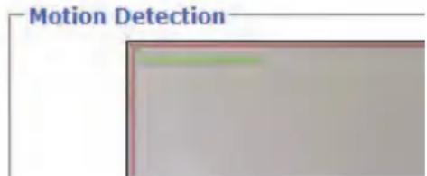
Show all areas: Check this box to show all configured motion areas in the preview video image.
Threshold value: Threshold value for triggering of a motion event
Sensitivity: Sensitivity setting of the motion area
For setting of the motion detection, an indicator in the preview video shows the current values of the threshold value and the current triggering value. This helps with the configuration of the threshold value and sensitivity.
Add:
Delete:
Remove a configured motion area. Before doing this, you need to select an entry from the list of motion areas.
6.9 Schedule
Name: Enter a name for the schedule.
Add: Press the button to add a schedule to the list.
Edit: Edit a schedule. Before doing this, select the relevant schedule.
Delete: Delete a schedule.
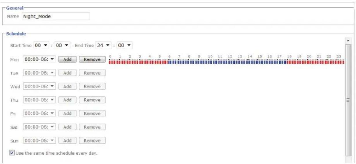
Start Time: Begin of the active time period
End Time: End of the active time period
Add: Adds a day to the active time period. Several time schedules can be defined for each day. Active time periods are marked in red; inactive time periods are marked in blue.
Delete: Delete a time period that was selected in the selection box of the day.
Use the same time period every day: The configuration of the day Monday ("Mo") is used for every day of the week.
6.10 System log
Relevant system data is logged in the system log. This can be useful for troubleshooting when installing the network camera. The data can also be sent to a log server.
Remote Log
□ Remote Log aktivieren

Aktueller Log
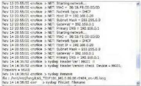
Activate remote log: Activate the remote log function by checking this box
Server name: IP address of the domain name of the log server
Server port: Port of the log server

Remote Log aktivieren


Accept the settings by pressing "SAVE" or cancel them by pressing "Cancel".
7. Maintenance and cleaning
7.1 Function test
Regularly check the technical safety of the product, e.g. check the housing for damage.
If safe operation is no longer possible, cease operating the product and safeguard it against accidental operation.
Safe operation is no longer possible under the following circumstances:
• The device shows visible damage.
• The device no longer works correctly.
- The device has been stored in adverse conditions for a long period of time.
- The device has been subjected to stress during transportation.

This product is maintenance-free for you. There are no components to service or anything inside the product to check. Never open it.
7.2 Cleaning
Clean the device with a clean, dry cloth. The cloth can be dampened with lukewarm water if it gets dirty.

Ensure that liquid does not penetrate the device, as this will cause damage. Do not use any chemical cleaning products, as they could damage the surface of the housing.
8. Disposal

Devices displaying this symbol may not be disposed of as domestic waste. At the end of its service life, dispose of the product according to the applicable legal requirements. Please contact your dealer or dispose of the products at the local collection point for electronic waste.
- Technical data
| Model number TVIP71501 TVIP71551 | ||
| Image sensor 1/4" progressive scan CMOS sensor | ||
| Camera type Day/night Day/night | ||
| Resolution 1280x720, 640x480, 320x240, 160x120 | ||
| Pixels (total) 1280x720 | ||
| Pixels (effective) 1280x720 | ||
| Lens 2.7~9 mm, F1.2 | ||
| Horizontal angle of view 81° - 25° | ||
| Digital zoom 10x | ||
| Day/night switching Electromechanical IR-cut filter Electromechanical IR-cut filter | ||
| Minimum illumination (color) 0.5 lux (IR off) / 0 lux (IR on) | ||
| Infrared LEDs | 12 IR LEDs | |
| IR range | 10 meters | |
| IR setting | 0-100% | |
| Image compression | H.264, MPEG-4, MJPEG | |
| Frame rate | H.264: 25 frames/sec @ 640x480 | |
| H.264: 25 frames/sec @ 1280x720 | ||
| MPEG-4: 25 frames/sec @ 640x480 | ||
| MPEG-4: 15 frames/sec @ 1280x720 | ||
| MJPEG: 25 frames/sec @ 640x480 | ||
| MJPEG: 25 frames/sec @ 1280x720 | ||
| Number of parallel streams | 4 | |
| Electronic shutter control | 1 - 1/17800 sec. | |
| White balance | Yes | |
| Amplifier control | 0-9 dB | |
| Backlight compensation | BLC, WDR | |
| Noise reduction | 2D DNR | |
| Motion detection | 3 zones | |
| Pre-alarm/post-alarm memory | Yes, 7 pre-alarm / 7 post-alarm images, 7 sec. pre-recording, 7 sec. post-recording | |
| Image overlay | Date, camera name, private zone | |
| Integrated memory | MicroSD slot SD/SDHC, max. 32 GB, class 6 | |
| Alarm input (NO/NC) | 1 | |
| Switching output | 1 (max. 12 V DC @ 100 mA) | |
| Alarm notification | E-mail / FTP / HTTP notification / switching output / network drive / microSD card | |
| Supported browsers | Mozilla Firefox, Safari, or Internet Explorer 6.x and higher | |
| Supported software | ABUS VMS | |
| Network access | RJ-45 Ethernet 10/100 Base-T | |
| Network protocols | Bonjour, TCP/IP, DHCP, PPPoE, ARP, ICMP, FTP, SMTP, DNS, NTP, UPnP, RTSP, RTP, HTTP, TCP, UDP, 3GPP/ISMA RTSP | |
| WLAN | - | IEEE 802.11b/g/n |
| PoE (Power over Ethernet) | PoE IEEE 802.11af | - |
| Encryption | HTTPS | HTTPS, WEP 64/128 bit, WPA/WPA2-PSK, WPS |
| Access protection | IP address filter, user name, password, 3 authorization levels | |
| Power supply | 12 V DC | |
| Current consumption | Max. 1 A | |
| Operating temperature 0°C - 50°C | ||
| Dimensions (Hx∅) | 94 x 145 mm | |
| Certifications | CE, RoHS, WEEE, REACH | |
| Model number TVIP72500 | ||
| Image sensor 1/4" progressive scan CMOS sensor | ||
| Camera type Day/night | ||
| Resolution | 1920 x 1080, 1280 x 1024, 1280 x 960, 1280 x 720, 1024 x 768, 640 x 480, 320 x 240 | |
| Pixels (total) 1920 x 1080 | ||
| Pixels (effective) 1920 x 1080 | ||
| Lens 2,7-9,0 mm, F1.5 | ||
| Horizontal angle of view 115°-37° | ||
| Digital zoom 10x | ||
| Day/night switching Electromechanical IR-cut filter | ||
| Minimum illumination (color) 0.5 lux (IR off) / 0 lux (IR on) | ||
| Infrared LEDs 12 IR LEDs | ||
| IR range 10 meters | ||
| IR setting 0-100% | ||
| Image compression H.264, MPEG-4, MJPEG | ||
| Frame rate H.264: 25 fps @ 1280x720 | ||
| H.264: 25 fps @ 1920x1080 | ||
| MPEG-4: 25 fps @ 1280x720 | ||
| MPEG-4: 15 fps @ 1920x1080 | ||
| MJPEG: 25 fps @ 1280x720 | ||
| MJPEG: 25 fps @ 1920x1080 | ||
| Number of parallel streams | 4 | |
| Electronic shutter control | 1-1/17800 sec. | |
| White balance | Yes | |
| Amplifier control | 0-9 dB | |
| Backlight compensation | BLC, WDR | |
| Noise reduction | 2D DNR | |
| Motion detection | 3 zones | |
| Pre-alarm/post-alarm memory | Yes, 7 pre-alarm / 7 post-alarm images, 7 sec. pre-recording, 7 sec. post-recording | |
| Image overlay | Date, camera name, private zone | |
| Integrated memory | MicroSD slot SD/SDHC, max. 32 GB, class 6 | |
| Alarm input (NO/NC) | 1 | |
| Switching output | 1 (max. 12 V DC @ 100 mA) | |
| Alarm notification | E-mail / FTP / HTTP notification / switching output / network drive / microSD card | |
| Supported browsers | Mozilla Firefox, Safari, or Internet Explorer 6.x and higher | |
| Supported software | ABUS VMS | |
| Network access | RJ-45 Ethernet 10/100 Base-T | |
| Network protocols | Bonjour, TCP/IP, DHCP, PPPoE, ARP, ICMP, FTP, SMTP, DNS, NTP, UPnP, RTSP, RTP, HTTP, TCP, UDP, 3GPP/ISMA RTSP | |
| PoE (Power over Ethernet) | PoE IEEE 802.11af | |
| Encryption HTTPS | ||
| Access protection | IP address filter, user name, password, 3 authorization levels | |
| Power supply | 12 V DC | |
| Current consumption | Max. 1 A | |
| Operating temperature | 0°C - 50°C | |
| Dimensions (Hx∅) | 94 x 145 mm | |
| Certifications | CE, RoHS, WEEE, REACH | |
10. GPL license information
Here we wish to inform you that the network surveillance cameras TVIP71501/TVIP71551/TVIP72500 contain Open Source Software, which is licensed exclusively under the GNU General Public License (GPL). To ensure that your use of the programs conforms with GPL, please refer to the GPL license conditions.
License text
The license text for the GNU General Public License can be viewed on the enclosed software CD or on the ABUS Security-Center homepage at http://www.abus-sc.de/DE/Service-Downloads/Software?q=GPL
Source code
The source code in use can be obtained from ABUS Security-Center upon request if you send an e-mail to license@abus-sc.com up to three years after purchase.
Executability of the overall system
The software packets (source code) do not enable you to set up a functional overall system. You also need a variety of software applications and the hardware developed for the network camera system.
Chère client, cher client,
4.3 Vue intérieure
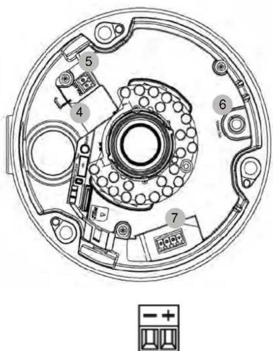
① Câble Ethernet Cat5
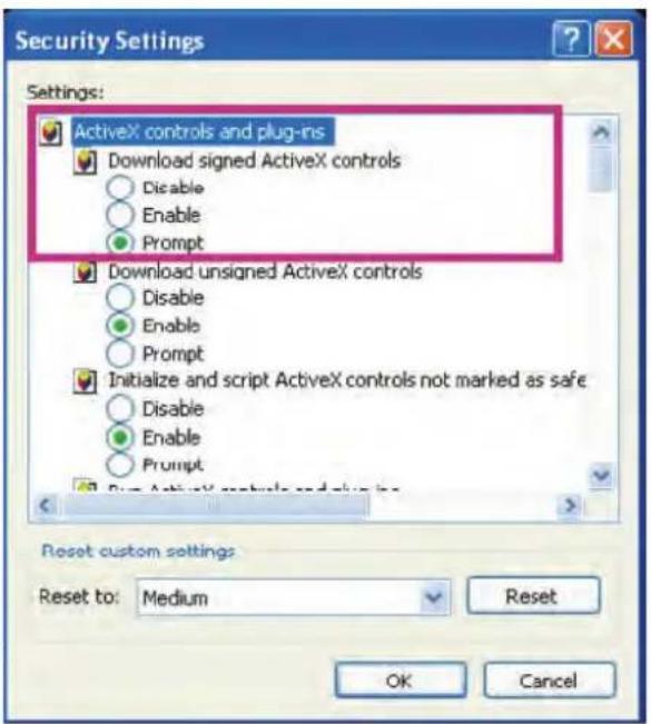

- VLC Media Player
• Real Player - Quicktime Media Player
rtsp://192.168.1.14:554/video.mp4 (MPEG-4 Stream)
rtsp://192.168.1.14:554/video.h264 (H.264 Stream)
Real Player
- Core Player
rtsp://192.168.1.14:554/video.3gp
Configuration
Acceuil
Paramétrage
Security Tech Germany
TVIP71501, TVIP71551: 1280x720, 640x480, 320x240, 160x120
TVIP72500: 1920x1080, 1280x1024, 1280x960, 1280x720, 1024x768, 640x480, 320x240
Standard Router (Gateway)
| 192 | . 168 | . 0 | . 28 |
| 255 | . 255 | . 0 | . 0 |
| 192 | . 168 | . 0 | . 1 |

* P=PTZ Action, D1/2=Digital Input 1/2, I=IR, F=FTP Upload, S=SMTP notification, H=HTTP notification, N=Network Storage, SD=SD Card
Généralités
Closed Circuit = fermé
Ajouter :
Supprimer :
6.10 Log système
Gebruiksaanwijzing
V e r s i e 0 9 / 2 0 CE 2
3.2 Kabellegging....181
3.3 Monteren van de camera 182
4.3 Binnenaanzicht

Taalpakket uploaden:
① CAT5 ethernetkabel


- VLC Media Player
• Real Player
• Quicktime Media Player
rtsp://192.168.1.14:554/video.mp4 (MPEG-4 stream)
rtsp://192.168.1.14:554/video.h264 (H.264 stream)
rtsp://192.168.1.14:554/video.3gp
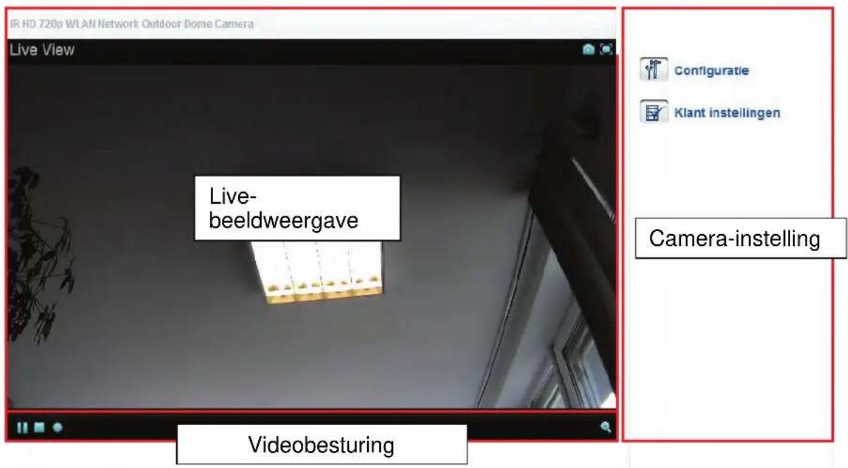
Live-beeldweergave
Setting
Home
Configuratie
Systeem
▶ Camera
▶ Weergeven
▶ Netwerk
Beveiliging
Evenementen
Systeem log

© Handmatige setting
(GMT+01:00)Amsterdam, Berlin, Bern, Rome, Stockholm, Vienna
Zomer tijd Aan Uit
Opslaan
Afbreken
TVIP71501, TVIP71551: 1280x720, 640x480, 320x240, 160x120
TVIP72500: 1920x1080, 1280x1024, 1280x960, 1280x720, 1024x768, 640x480, 320x240
Standard Router (Gateway)
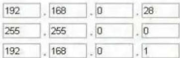
Accountgegevens invullen:


* P=PTZ Action, D1/2=Digital Input 1/2, I=IR, F=FTP Upload, S=SMTP notification, H=HTTP notification, N=Network Storage, SD=SD Card
Algemeen
Toevoegen:
Wissen:
6.10 Systeemlog
1 - Kabelgennemføring (i siden)
2 – Kabelgennemføring (bundplade, skjult)
3 - Antenne (kun TVIP71551)
4.3 Set indefra

① Cat5-Ethernet-kabel


• VLC Media Player
Real Player
- Quicktime Media Player
rtsp://192.168.1.14:554/video.mp4 (MPEG-4-stream)
rtsp://192.168.1.14:554/video.h264 (H.264-stream)
- Real Player
- Core Player
rtsp://192.168.1.14:554/video.3gp
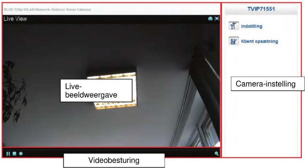
Live-beeldweergave
Indstilling
Hjem
Indstilling
TVIP71501, TVIP71551: 1280x720, 640x480, 320x240, 160x120
TVIP72500: 1920x1080, 1280x1024, 1280x960, 1280x720, 1024x768,
640×480, 320×240
TVIP71501, TVIP71551: 1280x720, 640x480, 320x240, 160x120
TVIP72500: 1920x1080, 1280x1024, 1280x960, 1280x720, 1024x768,
640x480, 320x240
TVIP71501, TVIP71551: 1280x720, 640x480, 320x240, 160x120
TVIP72500: 1920x1080, 1280x1024, 1280x960, 1280x720, 1024x768,
640×480, 320×240
Standard Router (Gateway)
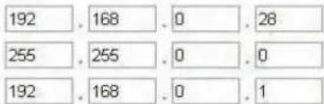
Accountgegevens invullen:


* P=PTZ Action, D1/2=Digital Input 1/2, I=IR, F=FTP Upload, S=SMTP notification, H=HTTP notification, N=Network Storage, SD=SD Card
Generelt
Closed Circuit = Lukket
Tilføj:
Instrukcja obsługi
Wersja 09/2012
CE
6.3 Pla yback....316
6.4 Sieć 319

3.2 Ułożenie kabla
① Kabel Ethernet Cat5
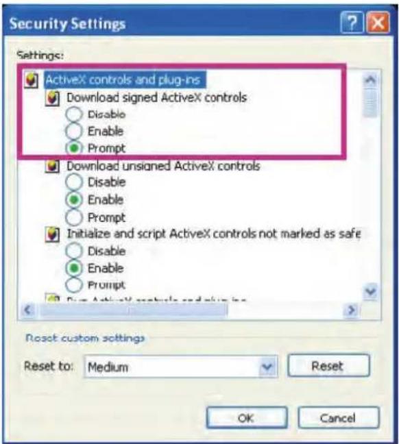

- VLC Media Player
- Real Player
- Quicktime Media Player
rtsp://192.168.1.14:554/video.mp4 (MPEG-4 Stream)
rtsp://192.168.1.14:554/video.h264 (H.264 Stream)
Real Player
- Core Player
rtsp://192.168.1.14:554/video.3gp

Configuration
Home
Setting
System
▶ Camera
▶ Playback
▶ Network
Security
Event
System Log

Welcome to Camera Settings Page
6.1 System
Informacje
TVIP71501, TVIP71551: 1280x720, 640x480, 320x240, 160x120
TVIP72500: 1920x1080, 1280x1024, 1280x960, 1280x720, 1024x768, 640x480, 320x240
TVIP71501, TVIP71551: 1280x720, 640x480, 320x240, 160x120
TVIP72500: 1920x1080, 1280x1024, 1280x960, 1280x720, 1024x768, 640x480, 320x240
TVIP71501, TVIP71551: 1280x720, 640x480, 320x240, 160x120
TVIP72500: 1920x1080, 1280x1024, 1280x960, 1280x720, 1024x768, 640x480, 320x240
TVIP71501, TVIP71551: 1280x720, 640x480, 320x240, 160x120
TVIP72500: 1920x1080, 1280x1024, 1280x960, 1280x720, 1024x768, 640x480, 320x240
Standard Router (Gateway)
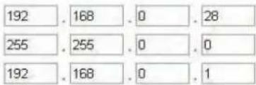


* P=PTZ Action, D1/2=Digital Input 1/2, I=IR, F=FTP Upload, S=SMTP notification, H=HTTP notification, N=Network Storage, SD=SD Card
Ogólne informacje
Nazwa
Open Circuit = otwarty
Dodaj
Kasuj
These operating instructions are published by ABUS Security-Center GmbH & Co.KG, Linker Kreuthweg 5, 86444 Affing, Germany. No reproduction (including translation) is permitted in whole or part e.g. photocopy, microfilming or storage in electronic data processing equipment, without the express written consent of the publisher. The operating instructions reflect the current technical specifications at the time of print. We reserve the right to change the technical or physical specifications.

Note de l'éditeur
© Copyright 09/2012 by ABUS Security-Center
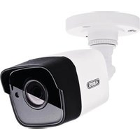
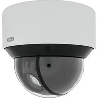
- TVIP71501/TVIP71551/TVIP72500
- BEDIENUNGSANLEITUNG
- 4.3 INNENANSICHT
- ALLGEMEIN
- 6.10 SYSTEMLOG
- IR HD 720P/1080P OUTDOOR NETWORK DOME CAMERA
- DISCLAIMER
- IMPORTANT SAFETY INSTRUCTIONS
- DEAR CUSTOMER
- CONTENTS
- USAGE IN ACCORDANCE WITH REGULATIONS
- SCOPE OF DELIVERY
- INSTALLATION
- 3.1 POWER SUPPLY
- 3.2 CABLE LAYOUT
- 3.3 INSTALLING THE CAMERA
- IMPORTANT
- CAMERA DESCRIPTION
- 4.1 EXTERIOR VIEW
- 4.2 OPENING THE CAMERA
- 4.3 INTERIOR VIEW
- 4.4 ALARM INPUT AND OUTPUT
- 4.5 SETTING THE ZOOM AND FOCUS
- 4.6 USING THE MICROSD SLOT
- 4.7 STATUS DISPLAYS
- 4.8 RESTORING THE FACTORY SETTINGS
- 4.9 USING THE ANALOGUE VIDEO OUTPUT
- 4.10 PUTTING INTO OPERATION
- DIRECT CONNECTION OF THE NETWORK CAMERA TO A PC / LAPTOP
- CONNECTING THE NETWORK CAMERA TO A ROUTER / SWITCH
- 4.11 ACCESSING THE NETWORK CAMERA FOR THE FIRST TIME
- 4.12 ACCESSING THE NETWORK CAMERA OVER A WEB BROWSER
- 4.13 INSTALLING THE ACTIVEX PLUG-IN
- 4.14 ADJUSTING THE SECURITY SETTINGS
- 4.15 PASSWORD PROMPT
- 4.16 ACCESSING THE NETWORK CAMERA OVER AN RTSP PLAYER
- 4.17 ACCESSING THE NETWORK CAMERA OVER A MOBILE PHONE
- 4.18 ACCESSING THE NETWORK CAMERA OVER ABUS VMS
- USER FUNCTIONS
- LIVE IMAGE DISPLAY
- CAMERA SETTINGS
- VIDEO CONTROL
- EXAMPLE
- CAMERA SETTINGS (CONFIGURATION)
- CONFIGURATION
- HOME
- SETTING
- 6.1 SYSTEM
- INFORMATION
- DATE/TIME
- ADJUST
- INITIALIZING
- LANGUAGE
- 6.2 CAMERA
- GENERAL
- ANALOG
- THE RESOLUTION 640X480 IS NOT AVAILABLE AND CANNOT BE CONFIGURED IF THE ANALOG VIDEO OUTPUT IS ACTIVATED UNDER "CAMERA / GENERAL
- H.264
- ACCEPT THE SETTINGS BY PRESSING "SAVE" OR CANCEL THEM BY PRESSING "CANCEL
- MPEG-4
- MJPEG
- 3GPP
- ADVANCED
- WHITE BALANCE
- EXPOSURE SETTINGS
- IRIS-CONTROL
- WIDE DYNAMIC RANGE
- NOISE REDUCTION
- SCHEDULE
- 6.3 PLAYBACK
- CLIENT PC
- NETWORK STORAGE
- SD CARD
- FILE NAMES / FOLDER NAMES
- 6.4 NETWORK
- NETWORK
- OBTAIN IP ADDRESS AUTOMATICALLY
- USE THE FOLLOWING IP ADDRESS
- USE THE FOLLOWING DNS SERVER ADDRESS
- PRIMARY DNS SERVER
- HTTP PORT NUMBER
- MAC ADRESSE
- 00:18 FE 00:00:00
- DDNS
- SETTING UP A DDNS ACCOUNT
- ACCESSING THE NETWORK CAMERA OVER DDNS
- RTSP
- MULTICAST
- UPNP
- BONJOUR
- WLAN ANTENNA (TVIP71551 ONLY)
- WPS (TVIP71551 ONLY)
- CONFIGURE VIA: PBC
- PIN
- 6.5 SECURITY
- USER
- HTTPS
- IP FILTER
- 6.6 EVENT
- 6.6.1 EVENT SERVER
- SERVER SETTINGS
- FTP
- SMTP
- HTTP
- NETWORK DRIVE
- MEDIA SETTINGS
- SNAPSHOT
- VIDEO
- SYSTEM LOG
- SD CARD STATUS
- 6.6.2 EVENT RECORDING
- EVENT CONFIGURATION
- MOTION DETECTION
- SWITCHING INPUT
- INTERVAL PROCESS
- UPON RESTART
- ICR FILTER
- STORAGE SPACE WARNING
- NETWORK CONNECTION INACTIVE
- IP NOTIFICATION
- ACTION
- 6.6.3 CONTINUOUS RECORDING
- 6.7 SWITCHING INPUT AND SWITCHING OUTPUT
- 6.8 MOTION DETECTION
- ADD
- DELETE
- 6.9 SCHEDULE
- 6.10 SYSTEM LOG
- MAINTENANCE AND CLEANING
- 7.1 FUNCTION TEST
- 7.2 CLEANING
- DISPOSAL
- GPL LICENSE INFORMATION
- 4.3 VUE INTÉRIEURE
- PARAMÉTRAGE
- GÉNÉRALITÉS
- AJOUTER
- SUPPRIMER
- 6.10 LOG SYSTÈME
- GEBRUIKSAANWIJZING
- 4.3 BINNENAANZICHT
- TAALPAKKET UPLOADEN
- LIVE-BEELDWEERGAVE
- CONFIGURATIE
- ALGEMEEN
- TOEVOEGEN
- 6.10 SYSTEEMLOG
- 4.3 SET INDEFRA
- INDSTILLING
- HJEM
- GENERELT
- 3.2 UŁOŻENIE KABLA
- INFORMACJE
- OGÓLNE INFORMACJE
- NOTE DE L'ÉDITEUR
Brand : ABUS
Model : TVIP71501
Category : Surveillance Camera