
TVCC40531 - Surveillance Camera ABUS - Free user manual and instructions
Find the device manual for free TVCC40531 ABUS in PDF.


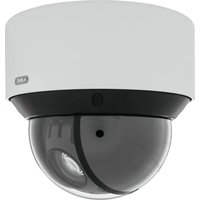
| Product type | Outdoor surveillance camera |
| Dimensions (L x H x D) | Approximately 70 x 70 x 150 mm |
| Weight | Approximately 450 g |
| Power supply | 12 V DC / PoE (Power over Ethernet) |
| Power consumption | Max. 6 W |
| Resolution | Full HD 1080p (1920 x 1080) |
| Viewing angle | 90° horizontal |
| Night vision | Up to 30 meters with IR LED |
| Protection rating | IP66 (weatherproof) |
| Connectivity | Ethernet RJ45 10/100 Mbps |
| Storage | Recording on microSD card (up to 128 GB) or NVR |
| Motion detection | Yes, built-in |
| Audio | Built-in microphone (unidirectional listening) |
| Operating temperature | -20 °C to +50 °C |
| Installation | Wall or bracket mounting, Ethernet cable required |
| Maintenance and cleaning | Clean the lens with a soft, dry cloth; periodically check connections |
| Security | SSL/TLS encryption, password protection |
| Spare parts and repairability | No spare parts available; contact ABUS customer service in case of failure |
Frequently Asked Questions - TVCC40531 ABUS
User questions about TVCC40531 ABUS
0 question about this device. Answer the ones you know or ask your own.
Ask a new question about this device
Download the instructions for your Surveillance Camera in PDF format for free! Find your manual TVCC40531 - ABUS and take your electronic device back in hand. On this page are published all the documents necessary for the use of your device. TVCC40531 by ABUS.
USER MANUAL TVCC40531 ABUS
natural_image
Exterior view of a black and silver BUR security camera with a metallic top (no text or symbols visible)These user manual contains important information for installation and operation. This should be noted also when this product is passed on to a third party. Therefore look after these operating instructions for future reference!
A list of contents with the corresponding page numbers can be found in the index on page 18.
FR
natural_image
Exterior view of a black and silver surveillance camera with a mounted sensor (no visible text or symbols)Version 06/2012
TVCC40531
CE
natural_image
Technical line drawings of mechanical components including a lathe, gear assembly, and wheel assembly (no text or labels)natural_image
Technical line drawing of a mechanical assembly with a cylindrical component and connected blocks (no text or symbols)6.2 Kabelverlegung
natural_image
Technical line drawing of a mechanical component with concentric rings and a directional arrow (no text or symbols)6.3 Stromversorgung
natural_image
Technical line drawing of a mechanical component with two labeled parts (1 and 2), no text or symbols present.(1) Videosignal (BNC)
natural_image
Technical line drawing of a mechanical assembly with a cylindrical component and a key inserted into a housing (no text or symbols)natural_image
Technical line drawing of a mechanical assembly with three cylindrical components connected by pipes (no text or symbols)IR Mini Easy Focus Outdoor Camera

natural_image
Exterior view of a black and silver surveillance camera with LED lights (no text or symbols visible)Version 06/2012
TVCC40531
CE
Original English user manual. Keep for future use.
UK Introduction
Dear Customer,
Thank you for purchasing this product.
This product meets the requirements of the applicable European and national guidelines. The corresponding declarations and documents can be obtained from the manufacturer (www.abus-sc.com).
To maintain this condition and to ensure risk-free operation, you as the user must observe these operation instructions!
Before initial start-up, read through the complete operating instructions observing operating and safety instructions.
All company and product names mentioned in this document are registered trademarks. All rights reserved.
If you have any questions, please contact your installer or your local dealer!

Disclaimer
This user manual was prepared with greatest care. If you should notice omissions or inaccuracies, please inform us about these on the back of this manual given address.
The ABUS Security-Center GmbH & Co. KG assumes no liability for technical and typographical faults and reserves the right to make at any time modifications to the product or user manual without a previous announcement.
The company is not liable or responsible for direct and indirect subsequent damages which are caused in connection with the equipment, the performance and the use of this product.
No guarantee for the content of this document is taken.
Important safety instructions

The warranty will expire for damage due to non-compliance with these operating instructions. We shall not be liable for any consequential loss!

We do not accept liability for damage to property or personal injury caused by incorrect handling or non-compliance with the safety-instructions. In such cases the warranty will expire.
Dear customer,
The following safety instructions are intended not only for the protection of your health, but also for the protection of the device. Please read through the following points carefully:
- There are no parts on the inside of the product which need to be serviced. Apart from this, the license (CE) and the guarantee/warranty will lapse if you open/take the product apart.
• The product will be damaged even it falls from a low height. - This device can be used in inside as well as outside.
- During the installation of the camera please take care that direct sunlight cannot fall onto the image sensor of the device. Please follow the installation instructions in the corresponding chapter of this user manual.
Avoid using the device under the following unfavorable ambient conditions:
- wetness or excessive air humidity
• extreme cold or heat - direct sunlight
- dust or combustible gases, vapors or solvents
• strong vibration
• strong magnetic fields, such as those found in the vicinity of machinery or loudspeakers - the camera should not positioned with opened iris towards the sun - this can lead to the destruction of the sensor.
- the camera may not be installed on unstable surfaces
General safety instructions:
- Do not leave packaging material lying around carelessly. Plastic/foil/bags and polystyrene parts etc. could become dangerous toys for children.
- For safety reasons don't give the camera into child hands due to them being able to swallow small parts.
- Please do not insert objects through the openings into the device.
- Use only accessories which are specified by the manufacturer.
Please do not connect incompatible parts to the device.
- Please pay attention to the safety instructions and user manuals of the other connected devices.
- Check the device for damages before installation. If this should be the case please do not use it.
- Please adhere to the operational voltage limitations listed in the technical data. High voltage could destroy the device and pose a health hazard (electric shock).

During the installation into an existing video surveillance system make sure that all devices are disconnected from the low and supply voltage circuit.
Immunity to conducted disturbances, inducted by radio-frequency fields (CS) - remark warning: Keep away to interference source, to make sure the function performance will be ensured.

If in doubt allow a professional electrician to mount, install and wire-up your device. Improper or make-do electrical connection to the mains does only represent at threat to you but also to other persons.
Wire-up the entire system making sure that the mains and low voltage circuit remain separated and cannot come into contact with each other in normal use or due to any malfunctioning.
Table of contents
- Intended use....19
- Explanation of symbol ......19
- Scope of delivery....19
- Features and functions ...... 19
- Description of device ....20
5.1 Overview – item numbers ......20
5.2 Unpacking 20
5.3 Description of camera 20
- Mounting....21
6.1 Mounting of the camera 21
6.2 Cable routing....22
6.3 Power supply....22
6.4 Connecting the video cable....23
6.5 Camera adjustment....23
6.5 Adjustment of zoom ratio 24
- Service and cleaning 25
7.1 Function test....25
7.2 Cleaning....25
-
Disposal....25
-
Technical data....26
1. Intended use
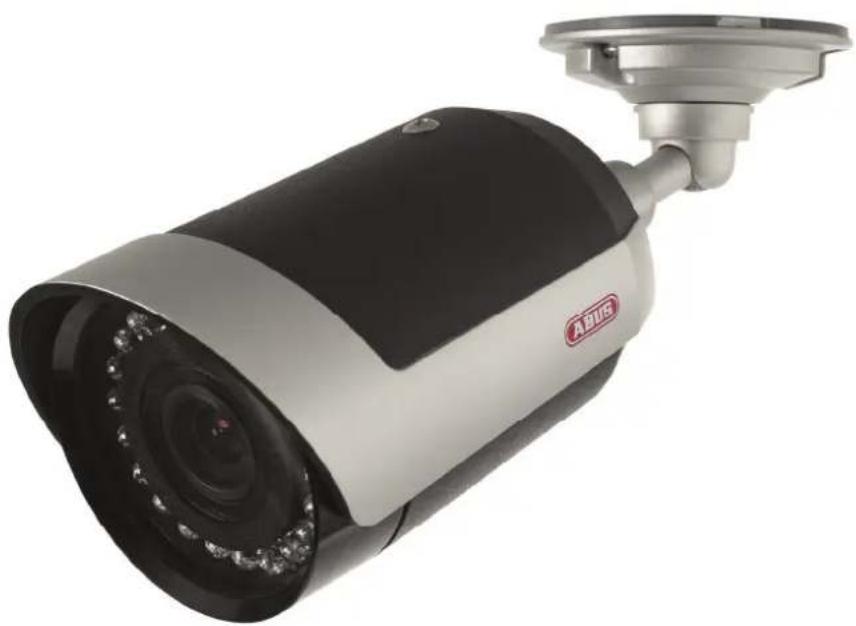
The IR mini Easy Focus outdoor camera is equipped with a high quality image sensor. It is used for video surveillance in connection with a recorder or monitor.
You can find a detailed description of functions in section "4. Features and functions".

Any other use than that described above can lead to damage to the product and in addition involve other risks. This does not include operation for other applications and would in case of doing so the guarantee and any related liability will lapse. This is also the case if any unauthorized changes or additions have been made to the product.
Please read through the entire manual carefully before putting this product into operation. This operating manual contains guidelines that are important for correct mounting and operating.
2. Explanation of symbol

A flash in the triangle is used if there is danger for the health, e.g. by an electric shock.

An exclamation mark in the triangle points to an important note in this user manual which must be minded.

This symbol can be found when you are to be given tips and information on operation.
3. Scope of delivery
- IR Mini outdoor camera
• Wall / ceiling mount (pre-installed)
• Installation material (screws, pegs, hexagon wrench) - User manual
4. Features and functions
- Compact outdoor camera with IR LEDs
• Automatic activation of IR light in case of low light condition - From outside accessible 5 - 15 mm motor zoom lens with Easy Focus function
- Synchronized control of IR intensity regarding zoom ratio
• Day/night function with removable ICR cut filter - Easy-Plug function for comfortable camera installation
• Fully cable managed
• Waterproof camera housing with IP66 protection - Including 3-axis camera bracket (pre-installed)
5. Description of device
5.1 Overview – item numbers
| Item number TVCC40531 | |
| Resolution | 520 |
| Lens | 5-15 |
| IR | √ |
| IR cut filter (ICR) | √ |
| Voltage | 12VDC |
TVL mm
5.2 Unpacking
While you are unpacking the device please handle it with utmost care.

If you notice any damage of the original packaging, please check at first the device. If the device shows damages, please contact your local dealer.
5.3 Description of camera
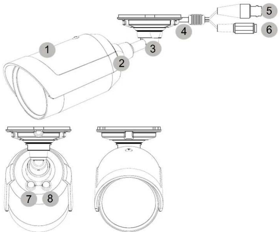
(1) Camera body with sunshield
(2) Joint between camera and camera bracket (Easy-Plug)
(3) Camera bracket
(4) Connection cable
(5) Connector for video signal
(6) Connector for power supply
(7) Zoom +
(8) Zoom -
6. Mounting
6.1 Mounting of the camera

Attention!
During the assembly the camera must be separated from the mains voltage.

Note!
The sunshield can be removed optionally. Please loosen the fixing screw at the top of the sunshield to remove the sunshield.
6.1.1. Please loosen the fixing screw at the top of the counter nut, using the supplied hexagon wrench.
Please loosen the counter nut by rotating the nut anti-clockwise, by using a suitable tool or wrench.
The camera module now can be removed from the camera bracket.
6.1.2. Put the camera bracket on a desired position, and please route the cable as described in chapter 6.2.
Please use the supplied installation material to fix the camera at desired position.
6.1.3. On putting back the camera module to the bracket, please take care of the alignment of both parts.

The inner side of the camera connection and the bracket front are flattened at one position. Those positions must match.
Those flattened positions are marked with red color!
Now screw the counter nut back and fix it by using the supplied hexagon wrench!

natural_image
Technical line drawings of mechanical components including a lathe, gear assembly, and a pulley (no text or symbols)6.1.4. The counter nut at the camera base will fix the ball type ankle.
The camera's angle of view can be adjusted like described in chapter 6.5. Please connect power and monitor first.

natural_image
Technical line drawing of a mechanical assembly with a cylindrical component and a key inserted into a housing (no text or symbols)6.2 Cable routing
For cable laying there are two ways available:
Hidden cable routing
In order to install the camera with a hidden cable laying you need to drill a hole into the surface and put through the cable. The camera bracket will cover the cable gland.
Surface cable routing
There is one knock out at the bracket base side to do surface cable routing.

natural_image
Technical line drawing of a mechanical component with no visible text or symbols6.3 Power supply
Before you start with the installation please make sure that the main voltage and the nominal voltage of the camera comply together.
natural_image
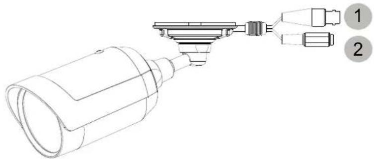
Technical line drawing of a mechanical component with two labeled parts (1 and 2), no text or symbols present.(1) Video signal (BNC)
(2) Power supply 12VDC

TVCC40531
The camera is run by a 12VDC power supply. Please observe the polarity. In order to connect a power supply a DC connector (5.5mm x 2.1mm) is preinstalled.
6.4 Connecting the video cable
To connect the video signal of the camera with a monitor or recorder, use a coaxial cable of the type RG59 with BNC-Connector (male) at the "VIDEO-OUT" connector.
The cable length up to the next device should not rise 100 meters.
6.5 Camera adjustment
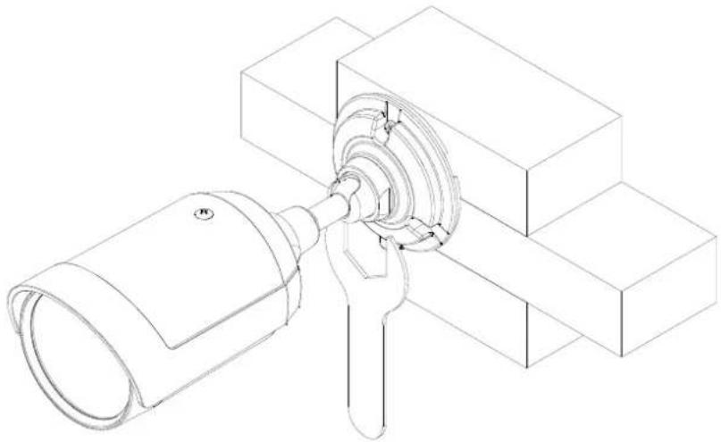
To adjust the viewing angle of the camera please loosen the counter nut at the base plate of the bracket by using a suitable tool or wrench. To do this please rotate the counter nut anti-clockwise.
natural_image
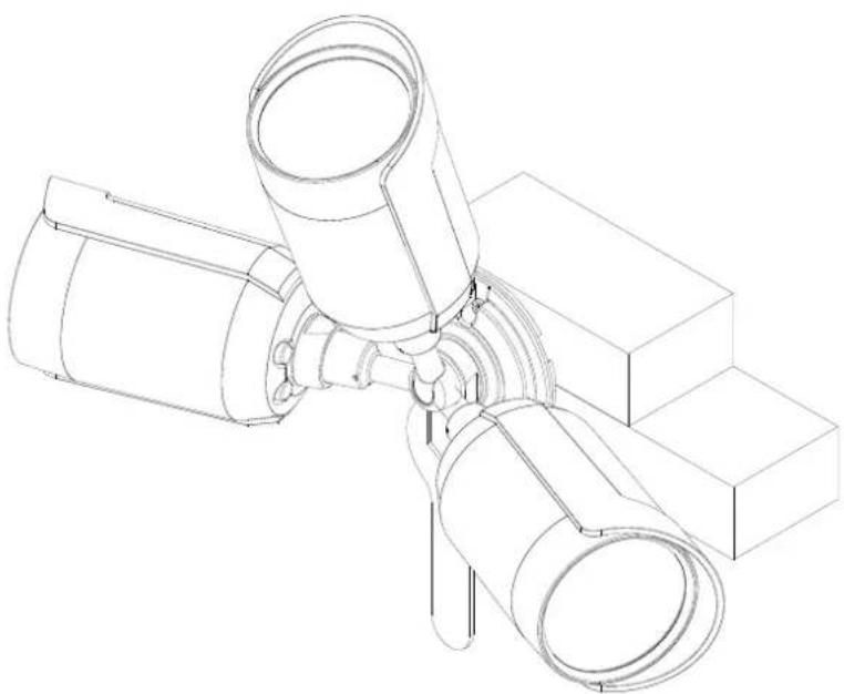
Technical line drawing of a mechanical assembly with a cylindrical component and rectangular blocks (no text or symbols)The adjustment now can be performed in three axis direction.
natural_image
Technical line drawing of a mechanical assembly with three cylindrical components connected to a base block (no text or symbols)After adjustment please fix the counter nut back.
6.5 Adjustment of zoom ratio
In case the buttons 7 or 8 won't be pushed, the key lock will be automatically activated after 15 minutes.
To deactivate the key lock, please push the button 7 or 8 for 10 seconds.
The zoom ratio will be adjusted using the two buttons on the camera back side. Function description:
| Key | Duration | Function |
| Left (7) Longer than 2 seconds | Shorter than 1 second | Zoom ratio plus 1x (0x, 1x, 2x, 3x, 4x)Stepwise zoom plus |
| Right (8) Longer than 2 seconds | Shorter than 1 second | Zoom ratio minus 1x (4x, 3x, 2x, 1x, 0x)Stepwise zoom minus |
| Left + Right (7+8) Longer than 3 seconds Set zoom ratio to 1x (default) | ||

In case the buttons 7 or 8 won't be pushed, the key lock will be automatically activated after 15 minutes.
To deactivate the key lock, please push the button 7 or 8 for 10 seconds.
7. Service and cleaning
7.1 Function test
Check the technical safety of the product such as damage to the housing at regular intervals.
When it can be assumed that the safe operation is no longer possible, the product must be put out of service and precautions taken o ensure that it is not used unintentionally.
It must be assumed that safe operation is not longer possible if
- the device shows visible signs of damage
- the device no longer operates and
- has been stored for longer periods under unfavorable conditions or
- has been subjected to considerable stress in transit.

Please note:
The product is absolutely maintenance-free for you. There are no components on the inside of the product to be checked or services by you, never open it.
7.2 Cleaning
Clean the product with a clean, soft cloth. To remove severe contamination, the cloth can be dampened with luke-warm water.

Make sure that no liquids can enter the equipment as the device can be destroyed. Never use chemical detergents as they could attack the surface of the device.
8. Disposal
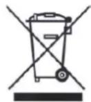
Products which are labeled with this pictogram may not be disposed by the domestic rubbish. Please dispose the product in accordance with the prevailing legal regulations at the end of its life time.
Please consult your dealer or dispose the product over the municipal gathering point for electric scarp.
9. Technical data
| Article number TVCC40531 | |
| TV Standard | PAL |
| Resolution | 520 TVL |
| Image sensor | 1/3" Sony Super HAD CCD |
| Picture elements (total) | 795(H) x 596(V) |
| Picture elements (effective) | 752(H) x 582(V) |
| Signal-to-noise ratio | 48 dB |
| Minimum illumination (day) | 0.5 Lux @ F2.2, 30 IRE |
| Minimum illumination (night) | 0 Lux @ F2.2, 30 IRE (IR On) |
| Day/night | Infrared cut filter (ICR), Color / B/W |
| IR LEDs | 21 LEDs [∅ 5 mm] |
| Lens (focal length) | f=5-15 mm, F2.2, 5 Levels (5,0 / 7,5 / 10,0 / 12,5 / 15,0 mm) |
| Horizontal angle of view | 41°~19° |
| Synchronisation | Internal |
| Automatic gain control (AGC) | AGC, Auto |
| Backlight compensation (BLC) | automatic |
| White balance | AWB |
| Protection class | IP66 |
| Video signal | FBAS; 1.0V p-p, 75 Ohm |
| Operating temperature | -10°C ~ +50°C |
| Humidity | 0~85%, Not condensing |
| Nominal supply voltage | 12 VDC |
| Current consumption (IR off) | 260 mA |
| Current consumption (IR on) | 425 mA |
| Dimensions (WxHxD) | 67.7 x 64.6 x 181 mm |
| Weight | 400 g |


natural_image
Exterior view of a black and silver surveillance camera with LED lights (no text or symbols visible)Version 06/2012
TVCC40531
CE
natural_image
Technical line drawings of mechanical components including a lathe, gear assembly, and spooling wheel assembly (no text or labels)natural_image
Technical line drawing of a mechanical assembly with a cylindrical component and a key inserted into a housing (no text or symbols)6.2 Câblage
natural_image
Technical line drawing of a mechanical component with no visible text or symbolsnatural_image
Technical line drawing of a mechanical assembly with two labeled components (1 and 2), no text or symbols present.natural_image
Technical line drawing of a mechanical assembly with a cylindrical component and a key inserted into a housing (no text or symbols)natural_image
Technical line drawing of a mechanical assembly with cylindrical components and rectangular blocks (no text or symbols)natural_image
Technical line drawing of a mechanical component with dimension标注 (26.2mm), no readable text or symbols present.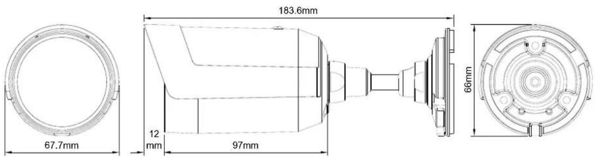
IR Mini Easy focus buitencamera
natural_image
Exterior view of a black and silver security camera with LED display (no text or symbols visible)Version 06/2012
TVCC40531
CE
natural_image
Technical line drawings of mechanical components including a lathe, gear assembly, and spooling machine (no text or symbols)natural_image
Technical line drawing of a mechanical assembly with a cylindrical component and a key inserted into a housing (no text or symbols)6.2 Bekabeling
natural_image
Technical line drawing of a mechanical assembly with no visible text or symbolsnatural_image
Technical line drawing of a mechanical assembly with two labeled components (1 and 2), no text or symbols present.(1) Videosignaal (BNC)
natural_image
Technical line drawing of a mechanical assembly with a cylindrical component and a key inserted into a housing (no text or symbols)natural_image
Technical line drawing of a mechanical assembly with three cylindrical components connected by rods (no text or symbols)IR Mini Easy Fokus Udendørskamera

natural_image
Exterior view of a black and silver security camera with LED display (no text or symbols visible)Version 06/2012
TVCC40531
CE
(1) Kamera med soltag
natural_image
Technical line drawings of mechanical components including a lathe, gear assembly, and wheel assembly (no text or labels)natural_image
Technical line drawing of a mechanical assembly with a cylindrical component and a key inserted into a housing (no text or symbols)6.2 Kabelføring
natural_image
Technical line drawing of a mechanical assembly with no visible text or symbols6.3 Strømforsyning
natural_image
Technical line drawing of a mechanical component with two labeled parts (1 and 2), no text or symbols present.(1) Videosignal (BNC)
natural_image
Technical line drawing of a mechanical assembly with a cylindrical component and rectangular blocks (no text or symbols)natural_image
Technical line drawing of a mechanical assembly with three cylindrical components and a base block (no text or symbols)natural_image
Exterior view of a black and silver BOS security camera with a mounted sensor (no text or symbols visible)Wersja 06/2012
TVCC40531
CE
natural_image
Technical line drawings of mechanical components including a lathe, gear assembly, and wheel assembly (no text or labels)natural_image
Technical line drawing of a mechanical assembly with a cylindrical component and a gear-like component (no text or symbols)6.2 Układanie kabli
natural_image
Technical line drawing of a mechanical assembly with no visible text or symbolsnatural_image
Technical line drawing of a mechanical assembly with two labeled components (1 and 2), no text or symbols present.natural_image
Technical line drawing of a mechanical assembly with a cylindrical component and a key inserted into a housing (no text or symbols)natural_image
Technical line drawing of a mechanical assembly with three cylindrical components connected by pipes (no text or symbols)natural_image
Technical line drawing of a mechanical component with dimension标注 (no text or symbols)
D Impressum
These operating instructions are published by ABUS Security-Center GmbH & Co.KG, Linker Kreuthweg 5, 86444 Affing, Germany. No reproduction (including translation) is permitted in whole or part e.g. photocopy, microfilming or storage in electronic data processing equipment, without the express written consent of the publisher.
The operating instructions reflect the current technical specifications at the time of print.
We reserve the right to change the technical or physical specifications.
© Copyright 06/2012 by ABUS Security-Center
- Kabelverlegung
- Stromversorgung
- IR Mini Easy Focus Outdoor Camera
- UK Introduction
- Disclaimer
- Important safety instructions
- Dear customer,
- Table of contents
- Intended use
- Explanation of symbol
- Scope of delivery
- Features and functions
- Description of device
- Overview – item numbers
- Unpacking
- Description of camera
- Mounting
- Mounting of the camera
- Attention!
- Note!
- Those flattened positions are marked with red color!
- Cable routing
- Power supply
- TVCC40531
- Connecting the video cable
- Camera adjustment
- Adjustment of zoom ratio
- Service and cleaning
- Function test
- Please note:
- Cleaning
- Disposal
- Technical data
- Câblage
- IR Mini Easy focus buitencamera
- Bekabeling
- IR Mini Easy Fokus Udendørskamera
- Kabelføring
- Strømforsyning
- Układanie kabli
- D Impressum
- © Copyright 06/2012 by ABUS Security-Center
Brand : ABUS
Model : TVCC40531
Category : Surveillance Camera