LU361PE - Lighting THEBEN - Free user manual and instructions
Find the device manual for free LU361PE THEBEN in PDF.
| Product type | Presence detector for lighting (models LU361PE, LU361PE2, LU361PE-S) |
| Brand | THEBEN |
| Model | LU361PE |
| Supply voltage | 230 V ~ 50 Hz |
| Number of contacts | LU361PE: 1 contact (10 A, 230 V); LU361PE2: 2 contacts (contact I: 10 A, contact II: 10 A, 230 V) |
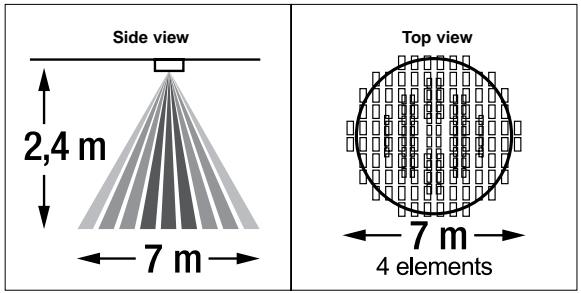
| Detection angle | 360° circular |
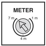
| Detection area | Approx. 7 meters in diameter at 2.4 meters height (adjustable from 1 to 7 m via METER button) |
| Number of detection zones | 304 zones |
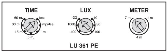
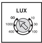
| LUX setting | 6 levels: 10, 30, 100, 400, 1000 lux, ∞ (infinity) |
| Time delay (lighting) | Test, pulse (1 s ON / 9 s OFF), 1 min, 5 min, 15 min, 30 min, 60 min |
| Time delay (heating/ventilation) | 10 s, 3 min, 15 min, 30 min, 60 min |
| Protection rating | IP40, Class II |
| Operating temperature | From -10°C to +45°C |
| Mounting | Ceiling, 65 mm diameter hole, ceiling thickness 5-25 mm |
| Package contents | 1 detector LU361PE or LU361PE2, 1 cable 30 cm (for PE2) or 3.5 m (for PE-S), 1 power supply housing, 1 manual |
| Additional features | Operating indicator LED, RJ11 connector, multi-directional detector, special lenses without dead zones, detection head adjustment (350° horizontal, 30° vertical) |
| Recommended uses | Offices, conference rooms, hotels, laundry rooms, kitchens, restrooms |
Frequently Asked Questions - LU361PE THEBEN
User questions about LU361PE THEBEN
0 question about this device. Answer the ones you know or ask your own.
Ask a new question about this device
Download the instructions for your Lighting in PDF format for free! Find your manual LU361PE - THEBEN and take your electronic device back in hand. On this page are published all the documents necessary for the use of your device. LU361PE by THEBEN.
USER MANUAL LU361PE THEBEN
natural_image
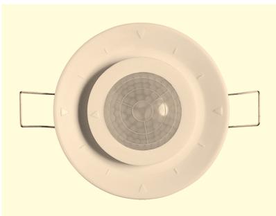
Top-down view of a white ceiling-mounted air vent with a circular vent and radial grille (no text or symbols)CARACTERISTIQUES TECHNIQUES
5 sec. / impulsion (1 sec. ON / 9 sec OFF)
natural_image
Illustration of a magnifying glass over a notepad with a hand holding a pen, no text or symbols presentFig. 10
natural_image
Diagram of a handheld device with rotating screen and directional arrow, no text or symbols presentnatural_image
Diagram of a mechanical device with an upward arrow and circular components, no text or symbols presentRemarque:
natural_image
Symmetrical geometric pattern with concentric circles and radial lines, no text or symbols presentFig. 16
text_image
TIME 2 TIME 1 LUX METER 30° 20° 10° 30° 10° 0° 9 8 7 6 5 4 3 2 1 0
B. Fonction LED
natural_image
Symmetrical geometric pattern with radial lines and arrow-like segments (no text or symbols)Procédure de test
natural_image
Top-down view of a circular ceiling light fixture with concentric rings and two side handles (no text or symbols visible)- Rated Voltage:
- Load:
TECHNICAL
SPECIFICATIONS
230V \~ 50Hz.
LU 361 PE2:
Dual independent load control.
Load I (L ↓): 10A max. (cos φ = 1)
Load II (D1-D2):10A max. (cos φ = 1)
voltage free contact (Load II is uncontrolled by LUX value, it can work at any light level).
LU 361 PE: Single load control (D1-D2): 10A max (cos φ = 1) voltage free contact.
LU 361 PE-S: Dual independent load control. Sensor with 3.5M cable. (Apply to LU 361 PE2 power box mainly)
360° circular.
About 7M diameter at 2.4M height.
10LUX/30LUX/100LUX/400LUX/1000LUX/\~∞ (6 Adjustments)
LU 361 PE2/LU 361 PE-S: Time 1:
For lighting: Test (LUX disable)/ impulse (1 sec. "ON"/ 9 sec. "OFF") / 1 min./5 min.
/15 min./30 min./60 min. (7 Adjustments)
Time 2: For HVAC: 10 sec./3 min.
/15 min./30 min./60 min. (5 Adjustments)
LU 361 PE Time: For lighting: Test (LUX disable) 5 sec./ impulse (1 sec.
"ON"/9 sec. "OFF") /1 min./ 5 min./
15 min./30 min./60 min. (7 Adjustments)
Adjustable for detection zones.
4 elements of super sensitive type.
304 zones.
Class II, IP40 (Sensor).
-10^ +45^.
- Detection Angle:
- Detection Pattern:
- Precise LUX Adjustment:
- Precise Time Adjustment:
- Meter:
- Sensor Element:
- Detection zone:
• Environmental Protection:
• Operation Temperature:
PACKAGE CONTENTS
| Pattern |  |  |  | |
| Item | LU 361 PELU 361 PE230 cm signal cable | LU 361 PE-S3.5 m signal cable | Power box(LU 361 PE only) | Manual |
| Quantity | 1 | 1 | 1 | 1 |
FEATURES
- Flush mount type.
- One additional sensor extendable - Sensor can be extended flexibly to enlarge detection coverage.
- Down light construction - Easy & quick installation to different thickness of ceiling boards.
- Patented adjustment design of sensor - Resolve dead angle of most current selling ceiling sensor in the market.
- Two relays for switching outputs (LU 361 PE-S) - One relay for lighting and another voltage free relay for HVAC (Heating, Ventilation, Air conditioner), or security camera, etc.
- Precise time - Provide 5 timer settings precisely from 1 min. to 60 min., plus test & impulse mode to convenient user while installing test or operation control Test mode: Convenient installation test (uncontrolled by LUX). Short impulse: Provide short triggering.
- Precise LUX - Free and convenient adjustment, precise operation under LUX setting value.
- Omni-directional quad element sensor - Provide super equal sensitivity of detection from different directions, not like conventional in line dual element sensors in the market.
- Unique lens pattern - Distribute total 304 zones “no dead spot” in its 360^ high intensity detection, such as a small waving movement can be detected.
- Red Led - Indicating triggering clearly and timely.
- Quick connector - RJ11 Connector easy for plug in connection.
FIELD OF VIEW
The LU 361 PE2 LU 361 PE LU 361 PE-S can be mounted on the ceiling and widely used in offices, conference rooms, hotels, utility rooms, kitchens and lavatories. While mounting on locations above mentioned, it is highly recommended to install at height of 2.4M and the detection range with a diameter of approx. 7M (See Fig. 1).
Fig. 1
text_image
Side view 2,4 m 7 m Top view 7 m 4 elements
INSTALLATION AND WIRING
A. Select A Proper Location
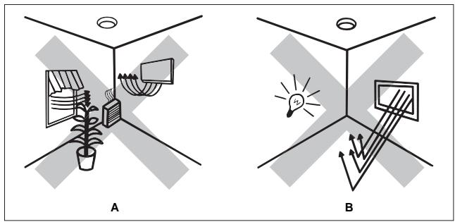
Since the sensor is in response to temperature change, please avoid the following conditions (See Fig. 2).
- Avoid directing the sensor toward areas or objects whose surfaces are highly reflective or are subject to rapid temperature change, such as pools.
- Avoid mounting the sensor near heat sources, such as heating vents, air conditioners, dryer as vents or lights.
- Do not aim the sensor toward light devices.
- Avoid aiming the sensor toward the objects which sways in the wind, such as curtain, miniature bushes, etc.
Fig. 2
text_image
A BB. Installation Procedure
Switch off power supply before installation.
- Please read the instruction manual carefully before installation
- Be sure all power supply is switched off.
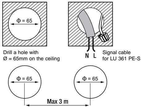
- To install the sensor, please drill a hole (diameter of 65 mm) on the ceiling and keep the power cable above ceiling board (SeeFig. 3).
Fig. 3
text_image
Drill a hole with Ø = 65mm on the ceiling Signal cable for LU 361 PE-S Ø = 65 Max 3 mNote:
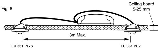
- When installing LU 361 PE2 and LU 361 PE-S on the same ceiling, assure the two holes is max. 3M away and the thickness of ceiling board is 5-25 mm (See Fig. 3 and 8).
-
Both LU 361 PE2 and LU 361 PE-S sensor can be connected to one power box at the same time. To install the second sensor (LU 361 PE-S), please keep the signal cable to pass through the hole (SeeFig. 3).
-
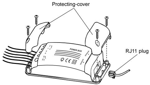
Unscrew protecting-cover on power box with a screwdriver. One terminal connects power supply and another connects RJ11 plug (See Fig. 4).
Fig. 4
text_image
Protecting-cover POWER BOX RJ11 plug-
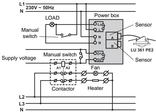
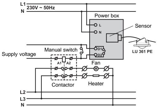
Wiring diagrams.
-
ONE SENSOR (See Fig. 5).
Fig. 5
text_image
L1 230V ~ 50Hz N LOAD Manual switch Power box Sensor A B LU 361 PE2 Sensor Supply voltage Manual switch A1 A2 Fan Contactor Heater L2 L3 NLU 361 PE2
Fig. 5
text_image
L1 230V ~ 50Hz N Power box Sensor L N D1 D2 LU 361 PE Supply voltage Manual switch A1 A2 Fan Contactor Heater L2 L3 NLU 361 PE
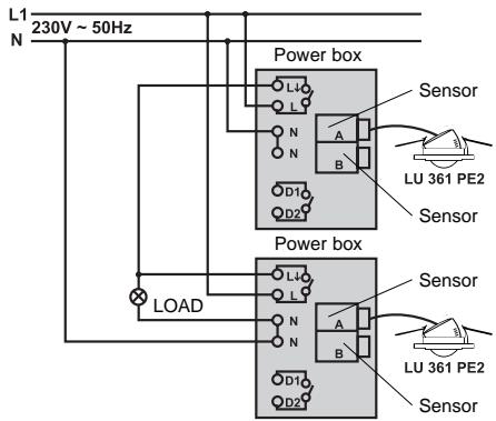
2. TWO LU 361 PE2 CONTROL ONE LOAD (Voir Fig. 6).
20
Fig. 6
text_image
L1 230V ~ 50Hz N Power box Sensor LU 361 PE2 Sensor LOAD Power box Sensor LU 361 PE2 SensorLU 361 PE2
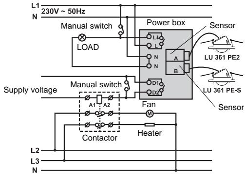
3. LU 361 PE2 and LU 361 PE-S TWO SENSORS CAN BE CONNECTED TO ONE POWER BOX AT THE SAME TIME (See Fig. 7).

Fig. 7
text_image
L1 230V ~ 50Hz N Manual switch LOAD Power box Sensor LU 361 PE2 A B LU 361 PE-S Sensor Supply voltage Manual switch A1 A2 Fan M Contactor Heater L2 L3 NLU 361 PE2
LU 361 PE-S
Note:
- Make sure wiring is connected correspondingly.
- Connect LU 361 PE-S at the same time (See Fig. 8). and refer to wiring diagram to connect it in parallel with the first sensor (LU 361 PE2) in power box (See Fig. 7).
text_image
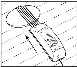
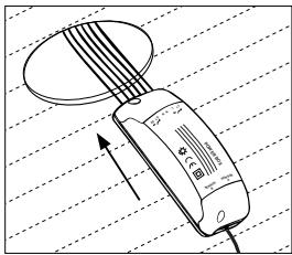
Fig. 8 Ceiling board 5-25 mm 3m Max. LU 361 PE-S LU 361 PE2- Refer to wiring diagram to connect wiring into power box terminal then replace protecting-cover and tighten it with screws (Voir Fig. 9).
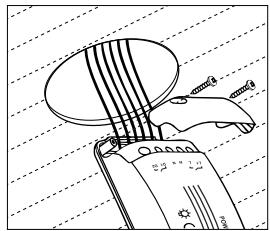
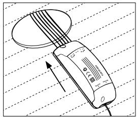
- Organize all wirings, then fix the power box with screws and mount it in the ceiling (Voir Fig. 10).
Fig. 9
natural_image
Illustration of a hand holding a pen with a magnifying glass over a circular object, against a grid background (no text or symbols)Fig. 10
natural_image
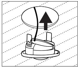
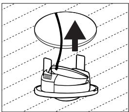
Diagram of a handheld device with a circular component and directional arrow, no text or symbols present- Insert sensor into the installation hole (See Fig. 11).
Fig. 11
natural_image
Diagram of a mechanical device with an upward arrow and internal components, set against a diagonal grid background (no text or symbols)22
Note:
- Insert two spring-clip pins into hole and press the sensor upward, then spring-clip pins will automatically stick on ceiling.
- Adjust sensor position and assure its bottom fixed tightly on ceiling (See Fig. 12).
Fig. 12
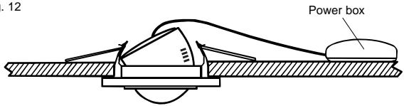
text_image
12 Power box- Wipe gently with a clean and dry cloth if the sensor surface is dirty.
- Restore power.
ADJUSTMENT AND WALK TEST
A. Adjust sensor head
Note:
- Slightly pull out sensor head with a screwdriver at OPEN mark before sensor head adjustment (See Fig. 13).

text_image
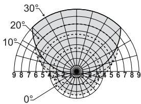
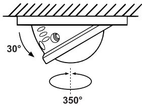
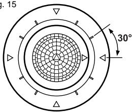
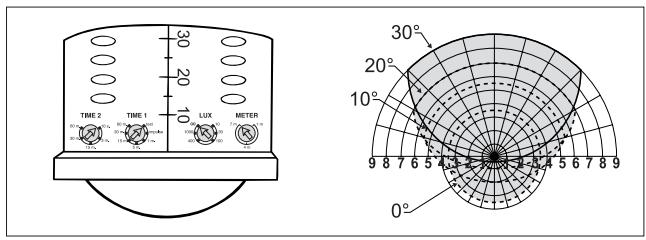
Fig. 13 OpenYou can adjust sensor head to meet your detection coverage. It can be adjusted horizontally 350^ (by 30^ step) vertically 30^ (by 5^ step) (See Fig. 14, 15 and 16).
Fig. 14
text_image
30° 350°Fig. 15
text_image
15 30°
natural_image
Symmetrical geometric pattern with concentric circles and radial lines, no text or symbols presentFig. 16
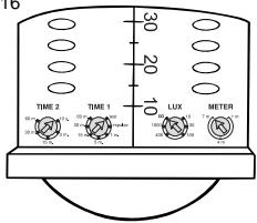
text_image
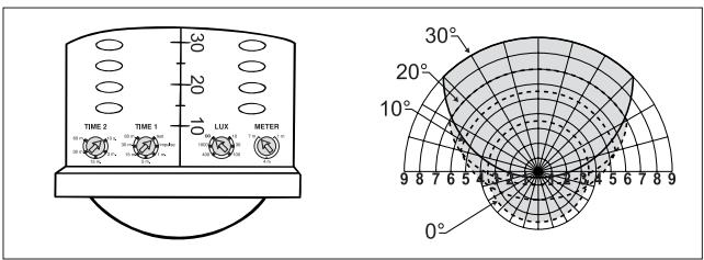
TIME 2 TIME 1 LUX METER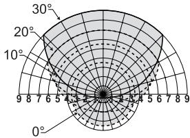
text_image
30° 20° 10° 0° 9 8 7 6 5 4 3 2 1 0 9B. LED Function
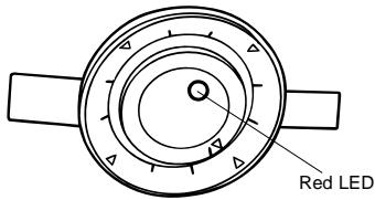
- LU 361 PE and LU 361 PE-S has one RED LED (See Fig. 17). It lights for 2 secs. Once the sensor is triggered and uncontrolled by LUX.
- LED can be regarded as indicator when performing a walk test without connecting any loads.
Fig. 17
text_image
Red LEDC. Walk Test
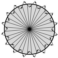
The purpose of the walk test is to check and adjust the motion sensor detection range. Turn “METER” knob to “7m”, “TIME 1” knob to “test”, then you can carry out a walk test and it is uncontrolled by LUX (See Fig. 18).
Note:
- When first time switches the power n or power is re-supplied again after the power is shut off, LED will turn on for 40 secs. then turn off. During the time of warming up, there is no output for LOAD I if it is in test & impulse mode, otherwise it has permanent output as LOAD II. Once any activities are detected after warming up period (40 secs.), LOAD I and LOAD II will operate according to prior settings. If there is no triggering in 20 secs. after warming up period, LOAD I and LOAD II will turn off automatically and won't be controlled by the settings of Time 1 & Time 2.
Fig. 18
natural_image
Symmetrical geometric pattern with radial lines and arrow-like elements (no text or symbols)Test Procedure
- Aim the sensor across to your desired detection zone.
- Switch the power on.
- Walk from outside across to the detection zone (See Fig. 18). Once the sensor is triggered, the light will turn on for 5 secs.
- Adjust sensor head to change coverage if necessary.
- Also can adjust METER knob to change coverage.
- Repeat step 3 to 5 until you are satisfied with the detection coverage.
KNOB SETTING
Note:
- Slightly pull out sensor head with a screwdriver before knobs adjustment (See Fig. 13).
LUX, METER, TIME knob
Adjust LUX, TIME, METER knobs according to the desired value marked beside each knob (See Fig. 19).
Fig. 19
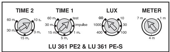
Time and LUX knobs must be set at value figure marked. DO NOT adjust knobs in between of two value figure marked to cause value functional failure or value confusion.
1. Precise LUX knob Setting
Fig. 20
text_image
LUX ∞ 1000 400 100 30* 6 adjustment Precise LUX: 10LUX/30LUX/100LUX/400LUX/1000LUX/\~∞

2. Precise TIME knob Setting
Fig. 21
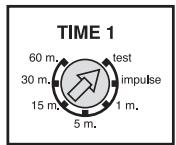
* Time 1/Time (for lighting):
7 adjustable Precise Time: Test (LUX disable)/impulse (1 sec. "ON"/9 sec. "OFF")/1min./5min./15min./30min./60min.
- Test mode: Time 1/Time knob setting to "test", the sensor automatically enters into test mode. In this mode light is uncontrolled by LUX. Light will turn on for 5 secs. then turn off once it is triggered. At the same time, LED will turn on for 2 secs. then turn off.
- Short impulse mode: Time 1/Time knob setting to "impulse", the sensor automatically enters into short impulse mode.
* Time2 (for HVAC): Uncontrolled by LUX (LU 361 PE2 only). 5 adjustable Precise Time: 10sec/3min./15min./30min./60min
3. METER knob Setting
Fig. 22
text_image
METER 7 m 1 m 4 m* Set METER knob to "1m", the sensor will operate within very limited small "field of view" with a diameter of approx. 1M.
* Set METER knob to "7m", the sensor will operate on the largest "field of view" with a diameter of approx. 7M.
* Set METER knob to middle position, the sensor will operate on the largest "field of view" with a diameter of approx. 4M.
TROUBLE SHOOTING
When sensor fails to work normally, check assumptive problems and suggested solutions in following table that will be hopeful to solve your
| Problem | Possible cause | Suggested solutions |
| LED does not turn on. | 1. Power does not switch on.2. Wiring is connected incorrectly. | 1. Check whether power is switched on.2. Refer to wiring diagrams and connect wiring correspondingly. |
| Lights does not turn on. | 1. Wiring is connected incorrectly.2. Defective load. | 1. Please check whether the power supply and load are connected correctly.2. Replace the defective load with a new one. |
| Lights does not turn off. | 1. Sensor is nuisance triggering.2. Wiring is connected incorrectly. | 1. Keep away from detection zone to avoid activating sensor while doing the test.2. Please check whether the power supply and load are connected correctly. |
| Nuisance triggering. | There are heat sources or any objects such as bushes which may sway in the wind within the detection coverage. | Avoid aiming the sensor toward any heat sources such as air conditioners, electric fans, heaters or any highly reflective surfaces. Make sure there is no swaying objects within the detection coverage. |
CE APPROVAL

LU 361 PE2 / LU 361 PE / LU 361 PE-S
RILEVATORE DI PRESENZA CON CREPUSCOLARE
natural_image
Top-down view of a circular ceiling-mounted air vent with mesh pattern and two side handles (no text or symbols)SPECIFICHE TECNICHE
natural_image
Simple line drawing of a lamp with a handle and base, enclosed in a square frame (no text or symbols)text_image
Φ = 65 Max 3 m Φ = 65Nota:
natural_image
Illustration of a hand holding a circular object with parallel lines, next to a device with a pointer (no text or symbols)Fig. 10
natural_image
Diagram of a handheld device with wires and a circular component, no text or symbols presentnatural_image
Diagram of a mechanical device with an upward arrow and circular component, no text or symbols presentNota:
natural_image
Symmetrical geometric pattern with concentric circles and radial lines, no text or symbols presentFig. 16
text_image
TIME 2 TIME 1 LUX METER 30° 20° 10° 30° 10° 0° 9 8 7 6 5 4 3 2 1 0B. Funzione del LED
text_image
LED rossonatural_image
Symmetrical geometric pattern with radial lines and arrowheads, no text or symbols presentnatural_image
Top-down view of a circular ceiling light fixture with concentric rings and a central mesh pattern (no text or symbols visible)
TECHNISCHE GEGEVENS
natural_image
Simple line drawing of a light bulb inside a square frame with diagonal hatching (no text or symbols)natural_image
Illustration of a hand holding a pen with a circular object above it, against a grid background (no text or symbols)Afb. 10

text_image
Diagram of a handheld device with labeled parts and directional arrows, showing measurement markings and grid lines.- De detector in de opening bevestigen (Zie Afb. 11).
Afb. 11
natural_image
Diagram of a device with a circular top and mechanical components, no text or symbols present50
Nota:
natural_image
Symmetrical geometric diagram with concentric circles and radial lines, no text or symbols presentAfb. 16

text_image
TIME 2 TIME 1 LUX METER