
TR 611 top2 24V - Digital timer THEBEN - Free user manual and instructions
Find the device manual for free TR 611 top2 24V THEBEN in PDF.


| Product Type | Digital Timer |
| Brand | Theben |
| Model | TR 611 top2 24V |
| Operating Voltage | 12 - 24 V AC/DC (+10%/-15%) |
| Frequency | 50 - 60 Hz |
| Power Consumption | max. 0.2 - 0.9 W |
| Max Switching Capacity | 16 A (250 V, cos φ = 1) |
| Min Switching Capacity | 10 mA/230 V AC, 100 mA/24 V AC/DC |
| Shortest Switching Time | 1 second |
| Protection Rating | IP20 (EN 60529) |
| Protection Class | II (subject to installation) or III for SELV |
| Operating Temperature | -30°C to +55°C |
| Power Reserve | 10 years at +20°C |
| Time Accuracy | ±0.25 s/day (25°C) |
| Rated Impulse Withstand Voltage | 4 kV |
| Pollution Degree | 2 |
| Channels | 2 (C1, C2) |
| Memory Cells | 84 |
| Functions | Switch, Pulse, Cycle, Holiday, PIN, External Input, Hour Counter |
| Memory Card Interface | OBELISK top2 |
| Mounting | DIN rail (EN 60715) |
| Connection Terminal | DuoFix® plug-in terminal (2 cables per position) |
| Safety | Installation only by qualified electrician; disconnect power before servicing |
| Maintenance | Clean with dry cloth; do not use solvents |
| Manufacturer | Theben AG, Hohenbergstr. 32, 72401 Haigerloch, Germany |
Frequently Asked Questions - TR 611 top2 24V THEBEN
User questions about TR 611 top2 24V THEBEN
0 question about this device. Answer the ones you know or ask your own.
Ask a new question about this device
Download the instructions for your Digital timer in PDF format for free! Find your manual TR 611 top2 24V - THEBEN and take your electronic device back in hand. On this page are published all the documents necessary for the use of your device. TR 611 top2 24V by THEBEN.
USER MANUAL TR 611 top2 24V THEBEN
307086
1. Basic safety information


WARNING
Danger of death through electric shock or fire!
➢ Installation should only be carried out by a qualified electrician!
- The device is designed for installation on DIN top hat rails (in accordance with EN 60715)
- The device corresponds to type 1 STU in accordance with IEC/EN 60730-2-7
- Power reserve (10 years) is reduced if memory card is inserted (using battery power)
OBELISK top2 memory card: Avoid mechanical overload and contamination during storage/transportation
2. Proper use
- The time switch is used for lighting, ventilation and flushing applications etc.
- Only for use in closed, dry rooms
Do not use on safety devices, e.g. escape route doors, fire safety equipment etc.
The external outputs are designed for operating voltage of 12-24 V AC and DC and not for 230 V.
Disposal
▶ Dispose of device in environmentally sound manner
3. Installation and connection
Mounting the time switch


WARNING
Danger of death through electric shock or fire!
➢ Installation should only be carried out by a qualified electrician!
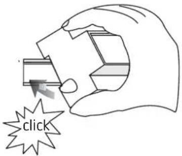

Mount on DIN top hat rails (as defined in EN 60715)
▶ Switched voltage-free
▶ Ensure device cannot be switched on
▶ Check absence of voltage
Earth and bypass
▶ Cover or shield any adjacent live components
Connecting the cable
Wiring diagrams 6114100 / 6224100
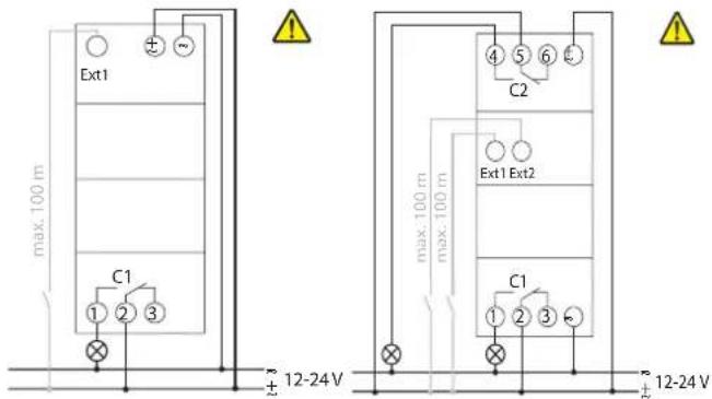
▶ Strip cable to 8 mm (max. 9)
Insert cable in the open DuoFix® plug-in terminal at 45°
① 2 cables per terminal position possible
To open the DuoFix® plug-in terminal, press screwdriver downwards
TR1522: With these devices the type of low voltage must correspond to low voltage type of the supply voltage (SELV = SELV, PELV = PELV, FELV = FELV).
If the switch output is 230 V, the time switch can be operated using low function voltage but not SELV as supply voltage.
▶ Lay the control cable separately from the load power.
Disconnecting the cable
- Use the screwdriver to push the load line connection opener downwards
4. Device description
Display & buttons

Operating instructions
- Read text line text/symbol represents query

flowchart
graph TD
    A["YES\nConfirmation"] --> B["NO\nModify/Change"]
    B --> C["Press"]
    C --> D["OK"]

flowchart
graph TD
    A["MENU"] --> B["PROGRAM"]
    B --> C["TIME/DATE MANUAL"]
    C --> D["CHANNEL C1"]
    C --> E["SET DATE"]
    C --> F["SU--WI"]
    C --> G["WEEK DAY"]
    C --> H["FORM DATE"]
    C --> I["FORM TIME"]
    C --> J["END"]
    D --> K["PERM ON"]
    D --> L["PERM OFF"]
    E --> M["OVERRI ON"]
    E --> N["TIMER"]
    E --> O["HOLIDAY"]
    E --> P["RANDOM"]
    E --> Q["END"]
    R["OPTIONS"] --> S["OPERATING HOUR"]
    S --> T["EXT INPUT"]
    T --> U["LCD ILLU-MINATION"]
    U --> V["LANGUAGE"]
    V --> W["PIN"]
    W --> X["FACTORY SETTING"]
    X --> Y["INFO"]
    Y --> Z["END"]
Initial operation

flowchart
graph TD
    A["MENU"] --> B["GERMAN"]
    B --> C["RETAIN PROGRAM"]
    C --> D["DELETE PROGRAM"]
    E["FRENCH"] --> F["ITALIAN"]
    F --> G["DUTCH"]
    H["FORM DATE"] --> I["YEAR"]
    I --> J["MONTH"]
    J --> K["DAY"]
    K --> L["FORM TIME"]
    L --> M["HOUR"]
    M --> N["MINUTE"]
    N --> O["SU-WI EUROPE"]
    O --> P["END"]
Set language, country, town/city, date, time as well as summer/winter time (SU-WI)
▶ Press any button and display follows on screen (see figure)
5. Settings and functions
Set switching time

flowchart
graph TD
    A["PROGRAM"] --> B["NEW"]
    B --> C["CHECK"]
    C --> D["MODIFY"]
    D --> E["DELETE"]
    E --> F["END"]
    G["SWITCH PULSE"] --> H["CHANNELC1"]
    H --> I["MEM FREE 84"]
    I --> J["ON"]
    J --> K["HOUR"]
    K --> L["MINUTE"]
    L --> M["MONDAY"]
    M --> N["COPY"]
    N --> O["ADD TUESDAY"]
    O --> P["SAVE"]
    Q["CYCLE"] --> R["Switching time for one day"]
    S["same switching time for several days = black"] --> N
① A switching time always consists of a start time and an end time
① There are 84 memory cells available
Example: Switch on sports hall lighting from Mon–Fri, 7:30 to 12:00 hrs
▶ Press MENU
▶ Select PROGRAM and press OK to confirm
▶ Select NEW and press OK to confirm
▶ Select SWITCH, confirm by pressing OK
▶ Select CHANNEL C1 or C2, confirm with OK
▶ Select ON (for turn-on times), confirm with OK
▶ Set required turn-on time (Mo–Fr, 7:30), confirm with OK
▶ Select COPY, confirm with OK
▶ ADD TUESDAY is displayed, confirm by pressing OK and also confirm the days We, Th, Fr by pressing OK.
▶ Continue with ▶ until SAVE is displayed.
▶ Confirm by pressing OK.
Repeat all steps for the turn-off time, however instead of selecting ON with ▶ select OFF and enter 12:00 for hour and minute.
Change switching times
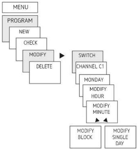
flowchart
graph TD
    A["MENU"] --> B["PROGRAM"]
    B --> C["NEW"]
    C --> D["CHECK"]
    D --> E["MODIFY DELETE"]
    E --> F["SWITCH CHANNEL C1"]
    F --> G["MONDAY"]
    G --> H["MODIFY HOUR"]
    H --> I["MODIFY MINUTE"]
    I --> J["MODIFY BLOCK"]
    I --> K["MODIFY SINGLE DAY"]
① You can either change or delete a block, i.e. a switching time copied for several days (e.g. Mon-Fri) or a single switching time
Change individual switching times
▶ Press MENU
▶ Select PROGRAM and press OK to confirm
▶ Select CHANGE, confirm by pressing OK
▶ Select SWITCH, confirm by pressing OK
▶ Select CHANNEL C1 or C2, confirm with OK
▶ Select day, confirm with OK
MODIFY HOUR, use the + or - buttons to change hour and minute and confirm with OK.
To change several switching times, select MODIFY BLOCK, confirm with OK
Delete switching program
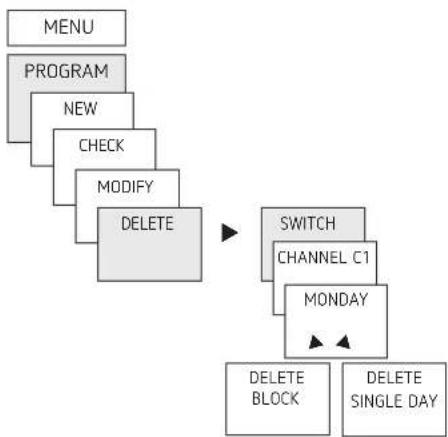
flowchart
graph TD
    A["MENU"] --> B["PROGRAM"]
    B --> C["NEW"]
    C --> D["CHECK"]
    D --> E["MODIFY"]
    E --> F["DELETE"]
    F --> G["SWITCH"]
    G --> H["CHANNEL C1"]
    H --> I["MONDAY"]
    I --> J["DELETE BLOCK"]
    I --> K["DELETE SINGLE DAY"]
① You can either delete a block, i.e. a switching time copied for several days (e.g. Mon-Fri) or a single switching time
▶ Press MENU.
▶ Select PROGRAM and confirm with OK
▶ Select DELETE, confirm with OK
▶ Select SWITCH, confirm with OK
▶ MONDAY is displayed, confirm with OK
▶ Select DELETE BLOCK, confirm with OK
▶ With ▶ DELETE MONDAY etc. individual days can also be cleared.
Pulse programming
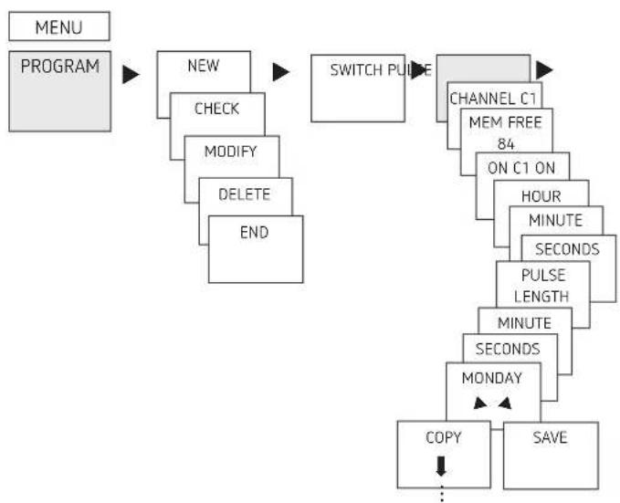
flowchart
graph TD
    A["MENU"] --> B["PROGRAM"]
    B --> C["NEW"]
    C --> D["CHECK"]
    D --> E["MODIFY"]
    E --> F["DELETE"]
    F --> G["END"]
    C --> H["SWITCH PULSE"]
    H --> I["CHANNEL C1"]
    I --> J["MEM FREE 84"]
    J --> K["ON C1 ON"]
    K --> L["HOUR"]
    L --> M["MINUTE"]
    M --> N["SECONDS"]
    N --> O["PULSE LENGTH"]
    O --> P["MINUTE"]
    P --> Q["SECONDS"]
    Q --> R["MONDAY"]
    R --> S["COPY"]
    S --> T["SAVE"]
    T --> U["..."]
Example: Switch on pause signal on Monday 8:05 hrs for 5 sec
▶ Press MENU
▶ Select PROGRAM, confirm with OK
▶ Select NEW, confirm with OK
▶ With ▶ select PULSE, confirm with OK
▶ Select CHANNEL C1 or C2, confirm with OK
▶ Select ON, confirm with OK
Use the + or - buttons to enter hour, minute, second (8:05)
and confirm with OK
▶ Use the + or - buttons to enter the duration of the pulse in minutes and seconds (5 sec) and confirm with OK. MONDAY is displayed.
▶ Select day, confirm with OK
▶ Select COPY or SAVE
▶ To save press ▶ and confirm with OK
To copy press OK
Cycle programming
In addition to turn-on and turn-off times (switching time) and short time pulses (pulse) cycle times (cycle) can also be programmed. The pulse duration (+ pulse pause) is limited to 17 hrs, 59 min, 59 sec
① Cycle times refers to cyclically repetitive time functions such as fan controls, urinal rinses etc.
Example: Switch on water rinsing Monday from 8:00 to 20:30 hrs every 15 min for 20 sec (8:00:00–8:00:20 On; 8:15:00–8:15:20 On; 8:30:00–8:30:20 On etc.)
Cycle programming:
• Start cycle: Monday 8:00 hrs
- Pulse duration: 20 s
- Pause duration (pause): 14 min and 40 s
• End cycle: Monday 20:30 hrs
① Observe the number of maximum electrical switching cycles when using the cycle function.

flowchart
graph TD
    A["MENU"] --> B["PROGRAM"]
    B --> C["NEW"]
    C --> D["CHECK"]
    D --> E["MODIFY"]
    E --> F["DELETE"]
    F --> G["END"]
    C --> H["CYCLE"]
    H --> I["CHANNEL C1"]
    I --> J["MEM FREE 84"]
    J --> K["START CYCLE"]
    K --> L["HOUR"]
    L --> M["MINUTE"]
    M --> N["MONDAY"]
    N --> O["PULSE LENGTH"]
    O --> P["PAUSE"]
    P --> Q["WITH END STOP CYCLE"]
    Q --> R["ENDLESS"]
    R --> S["..."]
▶ Press MENU
▶ Select PROGRAM, confirm with OK
▶ Select NEW, confirm with OK
▶ With ▶ select CYCLE, confirm with OK
Select CHANNEL C1 or C2, confirm with OK
START CYCLE is displayed, confirm with OK
Use the + or - buttons to enter hour, minute, day (8:00 hrs
Monday) and confirm with OK
Enter PULSE LENGTH (20 s), confirm with OK
Enter pause duration PAUSE (14 min and 40 s), confirm
with OK
▶ Select WITH END, confirm with OK
▶ STOP CYCLE is displayed, confirm with OK
➢ Enter end times of the cycle (20:30 hrs) and confirm with
OK
Setting holiday function

flowchart
graph TD
    A["MENU"] --> B["MANUAL"]
    B --> C["CHANNEL C1"]
    C --> D["PERM ON"]
    D --> E["PERM OFF"]
    E --> F["OVERRI ON"]
    F --> G["TIMER"]
    G --> H["HOLIDAY"]
    H --> I["RANDOM"]
    I --> J["END"]
    J --> K["ON"]
    K --> L["BEGINn HOLIDAY"]
    L --> M["..."]
    M --> N["END HOLIDAY"]
    N --> O["..."]
▶ Press MENU
▶ Select MANUAL and press OK to confirm
▶ Select CHANNEL C1 or C2, confirm with OK
▶ Select HOLIDAY and press OK to confirm
▶ Select ON and press OK to confirm
▶ Select START HOLIDAY and press OK to confirm
Enter YEAR, MONTH, DAY, HOUR and press OK to confirm
▶ Select END HOLIDAY and press OK to confirm
Enter YEAR, MONTH, DAY, HOUR and press OK to confirm
Activating PIN code
The PIN code is set in OPTIONS via the menu.
① If you have forgotten your PIN, call the Theben Hotline.
① Have the serial number ready

flowchart
graph TD
    A["MENU"] --> B["OPTIONS"]
    B --> C["OPERATING HOURS"]
    C --> D["EXT INPUT"]
    D --> E["LCD ILLU-MINATION"]
    E --> F["LANGUAGE"]
    F --> G["PIN"]
    G --> H["FACTORY SETTING"]
    H --> I["INFO"]
    I --> J["END"]
    G --> K["NO PIN WITH PIN CURRENT"]
    K --> L["PIN"]
    L --> M["NEW PIN 00 00"]
Setting manual or permanent switching
Manual or permanent switching can be set via the menu in MANUAL or (in the automatic screen) by button combination (see picture).
- Manual control:
Reversing the channel status to the next automatic or programmed switching.
- Permanent switching:
As long as a permanent switching (on or off) is activated, the programmed switching times are ineffective


Activating manual control
▶ Briefly press both buttons simultaneously
Activating permanent switching
▶ Press both buttons simultaneously for 2 seconds
Cancelling manual/permanent switching
▶ Press both buttons simultaneously
Set external input
For the channel, an EXTERNAL INPUT (see figure) can be set with different functions.
3 sub-menus can be selected: Inactive, push button (function), switch (function)
• INACTIVE: The external input has no function
- PUSH BUTTON: Manual (manual control), Timer (countdown timer) are selectable
- SWITCH: Permanent On, permanent Off are selectable
① If a function is activated via an external push button or switch, EXTERNAL is displayed.

flowchart
graph TD
    A["MENU"] --> B["OPTIONS"]
    B --> C["OPERATING HOURS"]
    C --> D["EXTERNAL OUTPUT"]
    D --> E["LCD ILLU-MINATION"]
    E --> F["LANGUAGE"]
    F --> G["PIN"]
    G --> H["FACTORY SETTING"]
    H --> I["INFO"]
    D --> J["CHANNEL C1"]
    J --> K["BUTTON"]
    K --> L["SWITCH"]
    L --> M["NOT ACTIVE"]
    M --> N["OVERRIDE TIMER"]
▶ Press MENU, with ▶ select EXT INPUT and follow the indications on the display.
Hour counter
The operating hours of the channel (relay) are displayed and deleted in the OPTIONS menu. If the number of operating hours exceeds the value set in the Service menu, SERVICE will appear in the display.
Example: Replace a lamp after after 5,000 h.
➢ Delete operating hours or set a higher value in Service (e.g. to 10,000 h)
Using the OBELISK top2 memory card
All functions can also be set on the PC using the OBELISK software and transferred to the device via the memory card.
▶ Insert memory card in the time switch
Read in/out saved switching times and device setups in the time switch or start Obelisk program
Remove memory card after copying etc.
Avid mechanical overload and contamination during storage/transport
i PC software OBELISK top2 available at www.theben.de

natural_image
Technical line drawing of a mechanical or electrical component with no visible text or symbolsCopying OBELISK → TIME
This copies the switching program and optionally all time switch settings (e.g. external input, time format etc.) from the memory card in the time switch.
Copying TIME → OBELISK
This copies all switch programmes and settings from the time switch to the memory card.
Starting OBELISK program
Takes on the switching times that are programmed on the memory card.
As soon as the memory card is removed, the switching times of the time switch are re-activated.

flowchart
graph TD
    A["OBELISK"] --> B["COPY OBELISK --> TSWI"]
    B --> C["OVERWRITE OK"]
    C --> D["TSWI → OBELISK"]
    D --> E["OVERWRITE OK"]
    E --> F["RUN OBELISK"]
    F --> G["CHECK OBELISK"]
Resetting the time switch
▶ Press the 4 buttons simultaneously
→ You can choose between KEEP PROGRAM and DELETE PROGRAM
6. Technical data
| Operating voltage: 12 - 24 V, +10 % / | -15 % |
| 12 - 24 V DC, +10 % / -15 % | |
| Frequency: | 50–60 Hz |
| Power consumption TR 611/622: | max. 0,2 W - 0,6 W / 0,2 W - 0,9 W |
| Max switching capacity: | 16 A (at 250 V, cos φ = 1) |
| switching capacity: | 2 A (at 250 V, cos φ = 0,6) |
| Min. switching capacity: | 10 mA/230 V AC |
| 100 mA/ 24 V AC/DC | |
| Shortest switching time: | 1 second |
| Protection rating: | IP 20 in accordance with EN 60529 |
| Protection class: | II in accordance withEN 60730-1 subject to designatedinstallation for supply with FELVand/or mains switching |
| Protection class: | III for supply with SELV and swit-ching of SELV |
| Operating temperature: | -30 °C ... +55 °C |
| Power reserve: | 10 years at +20 °C |
| Time accuracy: | ±0,25 s/day (25 °C) |
| Rated impulse withstand voltage: | 4 kV |
| Pollution degree: | 2 |
| Contact: | two way switch |
| Glow lamp load (4 A): | 1000 W |
| Halogen lamp load (4 A): | 1000 W |
| Fluorescent lamp load: uncorrectedSeries corrected (4 A):parallel-corrected: | 1000 VA80 W (max. 12 μF) |
| Compact fluorescent tubes (EVG) 230 V: | 30 W |
| LED lamps (<2 W) (230 V): | 6 W |
| LED lamps (>2 W < 8 W) (230 V): | 20 W |
| LED lamps (>8 W) (230 V): | 20 W |
7. Contact
Theben AG
Hohenbergstr. 32
72401 Haigerloch
GERMANY
Tel. +49 7474 692-0
Fax +49 7474 692-150
Hotline
Tel. +49 7474 692-369
hotline@theben.de
Addresses, telephone numbers etc.
www.theben.de


- Basic safety information
- Proper use
- Disposal
- Installation and connection
- Mounting the time switch
- Connecting the cable
- Disconnecting the cable
- Device description
- Operating instructions
- Settings and functions
- Change individual switching times
- Cycle programming
- Activating PIN code
- Setting manual or permanent switching
- Activating manual control
- Activating permanent switching
- Cancelling manual/permanent switching
- Set external input
- Hour counter
- Using the OBELISK top2 memory card
- Copying OBELISK → TIME
- Copying TIME → OBELISK
- Starting OBELISK program
- Resetting the time switch
- Technical data
- Contact
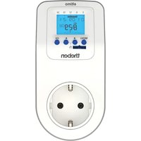
Brand : THEBEN
Model : TR 611 top2 24V
Category : Digital timer