
RAMSES 816 top2 OT - Thermostat THEBEN - Free user manual and instructions
Find the device manual for free RAMSES 816 top2 OT THEBEN in PDF.


| Product Type | Programmable Room Thermostat with OpenTherm |
| Brand | Theben |
| Model | RAMSES 816 top2 OT |
| Dimensions (H x W x D) | 82 x 82 x 25 mm |
| Weight | 150 g |
| Power Supply | 230 V AC, 50/60 Hz |
| Power Consumption | < 2 W stand-by |
| Display | LCD with backlight |
| Communication Interface | OpenTherm (OT) compatible |
| Control Type | PI (proportional integral) control |
| Temperature Range (heating) | 5°C to 30°C |
| Temperature Range (cooling) | 10°C to 35°C |
| Accuracy | ±0.5°C at 21°C |
| Programs | 7-day, 4 time periods per day |
| Special Modes | Party, Holiday, Frost protection |
| Mounting | Wall-mounted, flush or surface |
| Protection Class | IP30 |
| Operating Temperature | 0°C to 40°C |
| Cleaning and Maintenance | Wipe with dry cloth; no solvents. |
| Safety | CE marked, EN 60730 compliant |
| Spare Parts / Repairability | Service by qualified technician; no user-serviceable parts. |
Frequently Asked Questions - RAMSES 816 top2 OT THEBEN
User questions about RAMSES 816 top2 OT THEBEN
0 question about this device. Answer the ones you know or ask your own.
Ask a new question about this device
Download the instructions for your Thermostat in PDF format for free! Find your manual RAMSES 816 top2 OT - THEBEN and take your electronic device back in hand. On this page are published all the documents necessary for the use of your device. RAMSES 816 top2 OT by THEBEN.
USER MANUAL RAMSES 816 top2 OT THEBEN
OT Box RAMSES top2 OT - Standard box

309560 04
GB
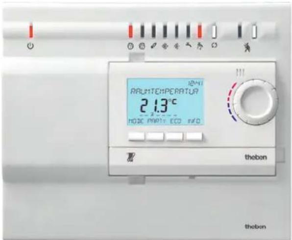
RAMSES 856 top2
Contents
Proper use 2
Disposal 2
Safety advice 3
Installation and dismantling 3
Connection 4
Terminal layout 5
Description 6
Start-up with RAMSES 850 top2 OT 7
Set TSP parameters (Transparent Slave Parameters) 8
Set heating curve of second heating circuit on controller 8
Systems/Applications 1–5 9
System 1 10
System 2 11
System 3 12
System 4 13
System 5 – comfort box 14
Switch chimney sweep function on/off 17
Operating hours counter 17
Connect USB/GSM modem 17
Error messages 18
Technical data 19
Service address/Hotline 20
Proper use
The heating controller RAMSES 856 top OT consists of the OT-Box RAMSES top2 OT as well as the room thermostat RAMSES 850 top2 OT, which transmits the values (target/actual values) via the Open-Therm bus. The 7-channel regulator regulates 2 heating circuits with the required circulation pumps and temperature sensors. In addition, the domestic hot water circulation is maximised via program control with optional legionella protection function. The range of functions can be extended via connection of 2 OT boxes.
- The device is intended for wall installation in the boiler room
- Corresponds to Type 1 B in accordance with IEC/EN 60730-1
- The entire system serves the purpose of digital heating regulation for time-dependent monitoring and control of room temperature (by means of circulation pumps, burner and/or motor mixing valve)
- It is used in dry rooms with normal levels of domestic cleanliness
- The controller is suitable only for the Heating-systems listed. For use in connection with other systems, contact the service department of Theben AG
- Accessories: optional: RAMSES 850 top2 OT (8509132), feed temperature sensor (9070371), plunge sensor (9070379), floor sensor (9070321), external temperature sensor (9070459), additional OT box for system 5 (standard box 9070712)
Disposal
Dispose of equipment in an environmentally sound manner
Safety advice

WARNING
Danger of death through electric shock or fire!
➢ Installation should only be carried out by a qualified electrician!
➢ Use correct type of fuse for external fuse! Overload leads to destruction of the relay. - Avoid excessive heat generation.
Installation
Remove baffle.
Unlock and remove upper part of OT box RAMSES top2 OT by turning the bayonet socket 90° anti-clockwise. ➢ Attach base of the OT Box RAMSES top2 to the wall with enclosed material. ➢ Click terminal into the terminal support and connect cable with the OT connection terminals. Power supply line of the OT bus, attach the outputs and sensors in accordance with the selected connection diagram to the connection terminals of the base (see connection diagram on page 9).
➢ Put on upper part of the OT-Box RAMSES top2 OT, click in and secure with bayonet socket. ➢ Afterwards optionally click in baffle or RAMSES 850 top2 OT in opening. ➢ Connect OT-Box RAMSES top2 to power supply.
Dismantling
Remove RAMSES 850 top2 OT or screen. ➢ Use a screwdriver to unlock upper part, remove and open device. If necessary take base from wall.

Connection

WARNING
Danger of death through electric shock!
➢ Must be installed by qualified electrician! ➢ Disconnect power source. ▶ Cover or shield any adjacent live components. ➢ Ensure device cannot be switched on! ➢ Check power supply is disconnected. Earth and bypass.
➢ Connect all consuming equipment (pumps, etc.) and sensors. Connect RAMSES 850 top2 OT via OT interface. Connect mains power between (L) (N) (terminal ①).

Inputs and outputs of the OT Box RAMSES top2 OT
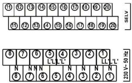
Terminal layout
Power connection ①
Outputs
- Heating circuit 1 pump as relay output ⑧
- Heating circuit 2 pump as relay output ⑦
- Burner as relay output ⑥
- Mixer closed (or 2nd burner stage) as relay output ⑤
- Mixer closed (or 2nd burner stage) as relay output ④
- Pump for domestic hot water feed as relay output ③
- Pump for domestic hot water circulation as relay output ②
Inputs
- Input fault ⑨ ⑩ (see page 4)
- OpenTherm-Slave (Connection RAMSES 850 top2 OT) ⑬
- OpenTherm-Master (Connection of second OT-Box) ⑭
- Domestic hot water temperature sensor ⑯
- Feed temperature sensor (mixer circuit) ⑰
- Boiler temperature sensor ⑱
- External temperature sensor ⑲ – Domestic hot water return temperature sensor (controls circulation pump) 20
The connected devices or sensors must be suitable for SELV or marked with protection class III.
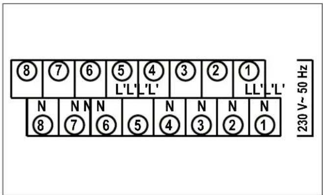

⑪ 12 15 ○ not used
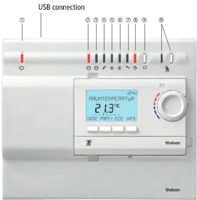
Description
① LED for operating state OpenTherm ② LED for pump 1 ③ LED for pump 2 ④ LED for burner (or error) ⑤ LED for mixer open ⑥ LED for mixer closed ⑦ LED for domestic hot water (DHW) feed ⑧ LED for domestic hot water (DHW) circulation ⑨ Button for switching outputs
(for test function without RAMSES 850 top2 OT)
⑩ Button and LED for chimney sweep function
Start-up with RAMSES 850 top2 OT
➢ After connection, the messages follow in the display (see image).
Language, room controls or OT controls, date, time and summer/winter time can be set in the MODE menu under TIME/DATE or SERVICE.
To set other functions, see operating manual for RAMSES 850 top2 OT.
![graph TD A["ROOM CONTROL"] --> B["GERMAN"] B --> C["YEAR"] C --> D["MONTH"] D --> E["DAY"] E --> F["HOUR"] F --> G["MINUTE"] G --> H["ROOM TEMPERATURE 21.6 °C"] I["EXTERNAL TEMPERATURE CONTROL"] --> A](/content/2026/06/1253659/images/249dafc812fbede2e2d6383fb516f7395b9218c813bfacd95cacdaa2b6965bbd.jpg)
- The OT box RAMSES top2 can be adapted for the particular heating system (5 systems) by setting different applications.
- The selection "Weather or room-dependent control" is made via the sensor connection. If an ambient temperature sensor is connected, it will be automatically detected and weather-dependent control will be carried out.
- All applications have a pump protection function.
- Almost all functions are controlled and displayed via RAMSES 850 top2 OT. The following messages are displayed:

HC Pump on

Burner on/off

Domestic hot water preparation on
Weather-dependent control
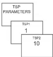
Set TSP parameters (Transparent Slave Parameters)
The TSP parameters are set in the SETTINGS menu.
Confirm TSP-PARAMETER with OK.
15 parameters can be set (see below).
Parameter 0 includes the 5 systems/applications.
Use + or – keys or rotary control to enter the value and confirm by pressing OK.
The value is transferred to the OT Box RAMSES top2 OT.
15 parameters are available from 0–14:
0 System selection (1, 2, 3, 4, 5 → default 1) 1 Boiler base temperature (10 ... 50 degrees, default 10 = off) 2 Max. feed temperature main circuit (30 ... 90 degrees, default 80) 3 Max. feed temperature auxiliary circuit (rear mixer) (30 ... 90 degrees, default 40) 4 Boiler hysteresis (1 ... 15 K, default 5) 5 Domestic hot water hysteresis (1 ... 10 K, default 5) 6 Domestic hot water priority / parallel operation (default ...) 7 Domestic hot water pump switch-off delay (0 ... 20 mins, default 10) 8 Domestic hot water for frost protection (default ...) 9 Time for domestic hot water circulation pump:
0: Domestic hot water circulation pump only runs when temperature-controlled
0–99: Domestic hot water circulation pump via ΔT on, Value is the maximum runtime in s
10 Pump protection time (0 .. 11 pm, default 12) 11 Pump protection duration in s (0...99, default 15, 0 = no pump protection) 12 ΔT for sequence control (5 ... 25, default 15) resolution 0.1 K 13 ΔT1 for pump switch heater 1 (5 .. 15 K, default 5 K) 14 ΔT1 for pump switch heater 2 (5 .. 15 K, default 5 K)
Further information available in product manual for OT box RAMSES top2 OT at www.theben.de.
Set heating curve of second heating circuit on controller
The heating circuit is adjusted in the SETTINGS menu.
On the room thermostat RAMSES 850 top2 OT, the heating curve for
2 heating circuits can be adjusted (see RAMSES 850 top2 OT operating guide, page 31). Base point2 and end point2, etc. must be set on the room thermostat.
Setting range: Base point 10–30 °C, default 20 °C
End point 25-60 °C, default 35 °C
Systems/Applications 1–5
- For the systems or applications 1-4, the OT-Box RAMSES top2 OT is required. The OpenTherm bus links RAMSES 850 top2 OT with the OT box RAMSES top2 OT.
- System 5 requires 2 OT boxes (centre box and end box),
which are linked via the OpenTherm bus. RAMSES 850 top2 OT as well as both boxes are linked with one another via the OpenTherm bus. The centre box must be linked to the 0–10 V (terminal 15 - 15) input with a wire bridge.
With the RAMSES 856 top2 OT, an additional OT box (standard box 9070712) will be required for this system.
RAMSES 850 top2 OT with 2-wire connection to 1 box![graph TD A["Device 1"] -->|OT| B["Device 2"] B --> C["Output"]](/content/2026/06/1253659/images/340d9b6c2b96baed7050ae1f094ace6287b3511fe38b73f5cfde299e2c3f6c63.jpg)
RAMSES 850 top2 OT with 2-wire connection to 2 boxes
![graph TD A["Power Supply"] --> B["Centre box"] B --> C["End box"] B --> D["OT"] B --> E["OT"] B --> F["* Wire bridge"] style B fill:#f9f,stroke:#333 style C fill:#ccf,stroke:#333 style D fill:#cfc,stroke:#333 style E fill:#fcc,stroke:#333 style F fill:#ffc,stroke:#333](/content/2026/06/1253659/images/9ff2492b9c11a257d48fe10cbc558683a961d205832af81a304d942e86b4edc6.jpg)
System 1
System 1 consists of a maximum of:
- Burner • Heating circuit without mixer • Heating circuit with mixer • Water storage tank • Domestic hot water circulation pump (Domestic hot water return pump)
The individual functions are activated by connecting the appropriate sensor, i.e. the domestic hot water program is only executed when the domestic hot water temperature sensor is connected.
Power connection ①-
Input configuration
• Domestic hot water temperature ⑯ - Feed temperature heating circuit 2 ⑰ - Boiler temperature ⑱ • Outdoor temperature ⑲ • Domestic hot water return temperature ⑳
Output configuration
• Heating circuit pump Heating circuit 1 ⑧ • Heating circuit pump Heating circuit 2 ⑦ - Burner ⑥ - Mixer + ⑤ - Mixer - ④ • Domestic hot water feed pump ③ • Domestic hot water circulation pump ②
![graph TD A["Boiler temperature sensor 18"] --> B["Heater"] B --> C["Boxer"] C --> D["Mixer 5"] C --> E["Mixer 4"] D --> F["Pump heating circuit 1 8"] E --> G["Pump heating circuit 2"] F --> H["Heating element"] G --> I["Feed temperature sensor 17"] H --> J["External temperature sensor 19"] I --> K["…](/content/2026/06/1253659/images/04f4add03f23d610fc3c625f9f3b24cd3e67c3403a96d18ff4222df37d75d31f.jpg)


System 2
System 2 (not for AT-dependent control) consists of a maximum of:
- Burner with 2 stages • Heating circuit without mixer • Water storage tank • Domestic hot water circulation pump (Domestic hot water return pump)
The individual functions are activated by connecting the appropriate sensor, i.e. the domestic hot water program is only executed when the domestic hot water temperature sensor is connected.
Power connection①-
Input configuration
• Domestic hot water temperature ⑯ - Boiler temperature ⑱ • Outdoor temperature ⑲ • Domestic hot water return temperature 20
Output configuration
• Heating circuit pump Heating circuit 1 ⑧ - Burner Stage 1 ⑤ - Burner Stage 2 ④ • Domestic hot water feed pump ③ • Domestic hot water circulation pump ②
![graph TD A["Boiler temperature sensor 18"] --> B["Pump heating circuit 1 8"] B --> C["Heating element"] C --> D["External temperature sensor 19"] E["Heater"] --> F["Domestic hot water temperature sensor 16"] F --> G["Pump domestic hot water feed 3"] G --> H["Service water tank"] H --> I["Domestic ho…](/content/2026/06/1253659/images/eb1e7adad06ba5b419e8f69447bef105290f3e4e78285440d41806fc0a5058c7.jpg)


System 3
System 3 consists of:
- Burner • Heating circuit without mixer • 2. Heater (e.g. solid fuel boiler)
- Buffer storage • Water storage tank • Domestic hot water circulation pump (Domestic hot water return pump)
The individual functions are activated by connecting the appropriate sensor, i.e. the domestic hot water program is only executed when the domestic hot water temperature sensor is connected.
Power connection ①-
Input configuration
• Domestic hot water temperature ⑯ - Feed temperature heating circuit 2 ⑰ - Boiler temperature ⑱ • Outdoor temperature 19 • Domestic hot water return temperature 20
Output configuration
• Heating circuit pump Heating circuit 1 ⑧ - Burner ⑥ - Pump 2. Heater ⑤ - Boiler pump (buffer storage feed pump) ④ • Domestic hot water feed pump ③ • Domestic hot water circulation pump ②
![graph TD A["Boiler temperature sensor 18"] --> B["Pump heating circuit 1"] C["Heizkörper"] --> D["Heating element"] E["Burner"] --> F["Relay burner 6"] F --> G["Boiler pump 4"] G --> H["Box"] H --> I["Pump second heater 5"] I --> J["Domestic hot water return temperature sensor 20"] J --> K["Service…](/content/2026/06/1253659/images/2b83c9a415c33c79f4f6db5dc5939eb1ef521e40ddb6fad007db63e923c9c80f.jpg)

System 4
System 4 consists of:
- Burner • Heating circuit without mixer • 2. Heater (e.g. solid fuel boiler)
- Buffer storage • Water storage tank • Domestic hot water circulation pump (Domestic hot water return pump)
The individual functions are activated by connecting the appropriate sensor, i.e. the domestic hot water program is only executed when the domestic hot water temperature sensor is connected.
Power connection①-
Input configuration
• Domestic hot water temperature ⑯ - Feed temperature ⑰ • Buffer storage temperature ⑱ • Outdoor temperature ⑲ • Temperature 2. Heater ⑳
Output configuration
• Heating circuit pump Heating circuit 1 ⑧ - Boiler pump ⑦ - Burner ⑥ - Mixer + ⑤ - Mixer - ④ • Domestic hot water feed pump ③ • Domestic hot water circulation pump ②
![graph TD A["Boiler temperature sensor 18"] --> B["Boiler pump 4"] B --> C["Boiler temperature sensor 17"] C --> D["Pump heating circuit 1 8"] D --> E["Pump domestic hot water circulation 2"] E --> F["Warpenerzeuger 20"] F --> G["Return temperature sensor 20"] G --> H["External temperature sensor 19"…](/content/2026/06/1253659/images/546e168516410c95a24d05c6f7da3f140e0106bb68b4a1a8c7e5fa971318cf91.jpg)


System 5 – comfort box
The Comfort box consists of RAMSES 850 top2 OT and 2 standard boxes (centre box and end box).
With it additional inputs/outputs are available for the connection of pumps, etc. Standard box (without RAMSES 850 top2 OT) can be obtained from Theben.
With the RAMSES 856 top2 OT an additional OT box (standard box 9070712) will be required for this system.
On the centre box attach wire bridge to input 0–10 V (terminal 15 – 15) (see figure).
System 5 consists of:
- Burner • Heating circuit 1 with mixer • Heating circuit 2 with mixer • 2. Heater (e.g. solid fuel boiler)
- Buffer storage
- Water storage tank
- Domestic hot water circulation pump (Domestic hot water return pump)
![graph TD RAMSE["RAMSES top2 OT with 2-wire connection to 2 boxes"] -->|OT| Box1["Centre box"] RAMSE -->|USB| EndBox["End box"] Box1 -->|OT| EndBox Box1 -->|* Wire bridge| EndBox Box1 -->|Input 0-10 V| Box1](/content/2026/06/1253659/images/682c5d3d8a242b0ec1a239d6a4c7fa4d5d8c93db43a722197caa72242c8477be.jpg)
Centre box
Power connection ①-
Input configuration
• RAMSES 850 top2 OT ⑬ - End box OT ⑭ - Wire bridge ⑮ • Buffer tank temperature top ⑯ - Feed temperature heating circuit 2 ⑰ • Temperature 2. Heater ⑱ - Lower buffer storage temperature 20
Output configuration
- Boiler pump (feed pump buffer storage) ⑥
- Mixer + Heating circuit 2 ⑤
- Mixer – Heating circuit 2 ④
- Pump 2. Heater ③
End box
Power connection ①-
Input configuration
• Domestic hot water temperature ⑯ - Feed temperature heating circuit 1 ⑰ - Boiler temperature ⑱ • Outdoor temperature ⑲ • Domestic hot water return temperature 20
Output configuration
• Heating circuit pump Heating circuit 1 ⑧ • Heating circuit pump Heating circuit 2 ⑦ - Burner ⑥ - Mixer + Heating circuit 1 ⑤ - Mixer – Heating circuit 1 ④ • Domestic hot water feed pump ③ • Domestic hot water circulation pump ②

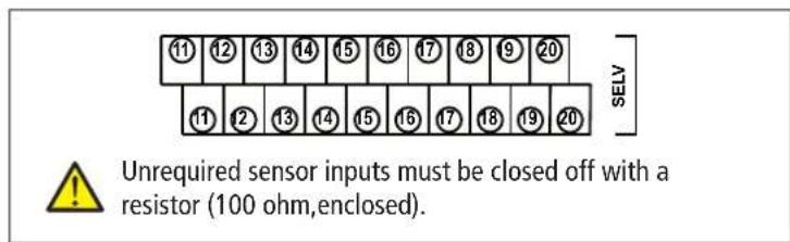
Unrequired sensor inputs must be closed off with a resistor (100 ohm, enclosed).
System 5
Comfort box with centre box and end box
![graph TD A["External temperature sensor End box 19"] --> B["Burner"] B --> C["Burner relay End box 6"] C --> D["Boiler temperature sensor End box 16"] D --> E["Boiler pump Centre box 6"] E --> F["Lower buffer temperature sensor Centre box 20"] F --> G["Domestic hot water temperature sensor End box 1…](/content/2026/06/1253659/images/4b09955f6c1a2b160a5467f8ef858fd6cc3c1ce963bbebf5b50fbe5395e454ba.jpg)
Switch chimney sweep function on/off
➢ Press button ✗ on the OT-Box RAMSES top2 OT x 1. The LED lights up. The chimney sweep function (burner + pump, for measurement of emissions by the chimney sweep) is on (full load). ➢ Press button again; the function is switched off. If not switched off manually the chimney sweeping function ends automatically after 30 mins.
In the RAMSES 850 top2 OT, the chimney sweeping function can also be switched on and off in the SETTINGS – CHIMNEY SWEEPING.
Operating hours counter
The values burner start and burner hours are determined in the OT box and displayed on the RAMSES 850 top2 OT.
➢ Press INFO button. The display shows

Connect USB/GSM modem
In the SETTINGS menu the additional sub-menu PIN CODE appears.
To protect the system, enter the four-digit code of the SIM card.
Operation via SMS
When you connect a USB/GSM modem to the OT-Box RAMSES top2 OT, the desired temperature/operating mode can be set via mobile phone.
1. Room-dependent control
To change the set point value, PIN number and temperature via SMS send to the USB/GSM modem: e.g. PIN:1234 Set:21.0 (note format!!) The USB/GSM modem sends an SMS with: PIN:Ok Set:21.0 Temp:19.0
To query the current temperature and settings, send the PIN number to the USB/GSM modem: e.g. PIN:1234
The USB/GSM modem sends an SMS with:
PIN: OK Set:21.0 Temp:19.0
When you receive PIN:xxxx Set:xx,x via SMS,
Replace the x with the correct PIN code/desired temperature.
2. Weather-dependent control
With the weather-dependent control, you can select the operating mode by SMS.
Send the PIN number and operating mode via SMS to the USB/GSM modem: e.g. PIN:1234 Set:2
1 = Frost protection mode
2 = Reduced mode
3 = Comfort mode
The USB/GSM modem sends an SMS with the set operating mode and current room temperature:
PIN: OK Set:2 Temp:19.0
To query the current temperature and settings, send the PIN number to the USB/GSM modem: e.g. PIN:1234
The USB/GSM modem sends an SMS with:
PIN: OK Set:2 Temp:19.0
When you receive PIN:xxxx Set:x via SMS,
Replace the x with the correct PIN code/desired operating mode.
Error messages
If an error occurs during the adjustment, error codes appear in the RAMSES 850 top2 OT display. Error codes 20-28 originate with a sensor error.
Error- Error code
11 11 NO COMMUNICATION
20 20 EXTERNAL TEMPERATURE ERROR
21 21 FEED ERROR 1
22 22 DOMESTIC HOT WATER ERROR
23 21 FEED ERROR 2
24 24 DOMESTIC HOT WATER RETURN ERROR
25 25 BOILER ERROR 1
26 25 BOILER ERROR 2
27 27 STORAGE ERROR 1
28 27 STORAGE ERROR 2
29 29 EXTERNAL FAULT ERROR
30 ---
31 31 MODEM ERROR

Technical data
- Operating voltage: 230 V~, +10/-15 % • Frequency: 50 Hz • Power consumption: typically 2.7 VA
- Standby: typically 1.1 W
- Switch load: Relay: 5 x max. 2 (1) A 230 V~ (burner, mixer open, mixer closed, domestic hot water pump, domestic hot water return pump)
Relay: 2 x 1 A (1 A)
230 V ~
(Heat pump 1, Heat pump 2)
- SELV power circuits: – Sensor inputs – OT (communication interface) – USB (data communications interface)
- Contact material: AgNi
- Contact: 7 x simple working contact (normally open)
- Permissible ambient temperature: 0°C to +50°C
- Contact position for power reserve: permanently to Off
- Protection class: II in accordance with EN 60730-1 subject to designated installation
- Protection rating: IP 20 in accordance with EN 60529; IP 65 for remote sensor
- Mode of operation: Type 1 B in accordance with EN 60730-1
- Pollution degree: 2
- Rated impulse withstand voltage: 4 kV
A detailed manual can be found at www.theben.de
Service address/Hotline
Service address
Theben AG
Hohenbergstr. 32
72401 Haigerloch
GERMANY
Telephone +49 7474 692 0
Fax +49 7474 692-150
Hotline
Telephone +49 7474 692 -369
Fax +49 7474 692-207
hotline@theben.de
Addresses, telephone numbers etc.
www.theben.de


- CONTENTS
- PROPER USE
- DISPOSAL
- SAFETY ADVICE
- WARNING
- DANGER OF DEATH THROUGH ELECTRIC SHOCK OR FIRE
- INSTALLATION
- DISMANTLING
- CONNECTION
- DANGER OF DEATH THROUGH ELECTRIC SHOCK
- TERMINAL LAYOUT
- POWER CONNECTION ①
- OUTPUTS
- INPUTS
- DESCRIPTION
- START-UP WITH RAMSES 850 TOP2 OT
- SET TSP PARAMETERS (TRANSPARENT SLAVE PARAMETERS)
- 15 PARAMETERS ARE AVAILABLE FROM 0–14
- SET HEATING CURVE OF SECOND HEATING CIRCUIT ON CONTROLLER
- SYSTEMS/APPLICATIONS 1–5
- SYSTEM 1
- INPUT CONFIGURATION
- OUTPUT CONFIGURATION
- SYSTEM 2
- POWER CONNECTION①
- SYSTEM 3
- SYSTEM 4
- SYSTEM 5 – COMFORT BOX
- CENTRE BOX
- END BOX
- SYSTEM 5
- SWITCH CHIMNEY SWEEP FUNCTION ON/OFF
- OPERATING HOURS COUNTER
- CONNECT USB/GSM MODEM
- OPERATION VIA SMS
- ROOM-DEPENDENT CONTROL
- WEATHER-DEPENDENT CONTROL
- ERROR MESSAGES
- TECHNICAL DATA
- SERVICE ADDRESS/HOTLINE
- SERVICE ADDRESS
- HOTLINE
Brand : THEBEN
Model : RAMSES 816 top2 OT
Category : Thermostat