USER MANUAL HD 600 CH KARCHER
natural_image
Exterior view of a Karcher industrial machine on a stand (no signage or text beyond brand name)
5.959-490
A 12578
(12/99)

natural_image
Icon of an open book with a lowercase 'i' and a number 1, symbolizing information (no text or symbols present)
Betriebsanleitung
natural_image
Close-up of a white electronic device's internal component with a labeled key (no readable text or symbols)
natural_image
Close-up of industrial piping and valve assembly with a labeled component 'CHEM' (no readable text beyond label)
natural_image
Silhouette of four different types of weapons or tools, including a pistol and three elongated sticks (no text or symbols visible)
Düsen
Operating Instructions English
natural_image
Exterior view of a KARCHER industrial machine on a stand (no signage or text beyond branding)
5.959-490
A 12578
(12/99)

natural_image
Icon showing an open book with a lowercase 'i' and a number 1, enclosed in a rounded square frame (no text or symbols on the book or background)
Operating Instructions
to be handed to the operator
Please read before operating the unit,
and keep in a safe place for future reference.
Proper disposal – for the sake of our environment
Packaging materials
The packaging components used to ship the unit are composed of wood and cardboard, i.e., environment-friendly materials, both of which can be easily sorted out and collected for recycling.
Engine oil
The equipment contains engine oil. Any waste oil collected during an oil change, as well as any oil-water mixture exiting from the machine in conjunction with a leak, must be collected and delivered to a waste-oil collection point.

Important!
Waste oil may be disposed of only at designated collection points. Please take used oil to these special installations. Remember: It is an offence to contaminate the environment with waste oil!
Cleaning detergents
All Kärcher cleaning detergents, as indicated by the ‘ASF’ designation, are designed to be separator-friendly. This means that they do not impede the function of oil separators. A listing of the recommended cleaning detergents is featured in the “Accessories” section.
A. For Your Safety
- System Operating Hazards
- Safety Instructions and Information
- Danger Sources
- Hazards posed by Accessories
- Noise Protection
- Workplaces
- Authorised Operators
- Personal Protective Equipment
- Safety Measures on the Installation Site
- Protective Devices
- Emergency drill
- Guidelines and Regulations
- Proper Use of the Equipment
F. Troubleshooting
G. Accessories
H. System Installation
- Placement
- Connections
- High-pressure Installation
- Mounting detergent reservoirs
- Hard-water Treatment
- Preparations for Commissioning
- Space Assignment Plan
I. Customer Service
B. System Operation
- Operator controls
- Switching off in case of emergency
- Operation
- Adjustment settings
- Stopping the System
- Frost Protection
- System Shut-Down
C. System Function
- Flow diagram
- Description of functions
D. Specifications
- HD 600 C(H)
- HD 1000 C(H)
- HD 1400 C(H)
- Dimension diagram
E. Maintenance
- System overview
- Notes on maintenance
- Maintenance Schedule
- Oil change
- Decalcification
1. System Operating Hazards
This system is equipped with an overpressure protection feature which was subjected to a safety inspection. Improper operation or abuse of this feature constitutes an hazard to health and life of the operator and/or third persons.
Any persons charged with the installation, commissioning, operation, maintenance or service of the machine are obligated:
■ to be appropriately qualified
■ to diligently observe these Operating Instructions.
Throughout the present Operating Instructions the following symbols are used:

Danger!
Denotes an immediate and present danger. Failure to observe this notice could lead to severe injury or death.

Caution!
Denotes a potentially hazardous situation. Failure to observe this notice could lead to minor injuries or property damage.

Important!
Denotes operating hints and important information.
3. Danger Sources
Sections of the water volume contained in the system are under high pressure. High-pressure water jets may exit from damaged system components, posing injury and/or scalding hazards.
General Hazard Overview

Danger!
■ Injury hazard through exiting water jet of high-pressure or high-temperature water. Even after the Emergency-STOP master switch has been activated, the system contains high pressure. After a system stop, release remaining system pressure by opening a high-pressure gun.
■ Burn injury hazard through hot system components.
During hot-water operation, do not touch non-insulated pipe installations and hose couplings. Grasp the jet lance by the grip surfaces only.
■ Injury hazard through flying debris. Flying debris or objects can cause injury to persons or animals. Never aim the water jet at fragile or loose objects.
■ Explosion hazard.
The use of this system in enclosed indoor areas is prohibited.
■ Explosion hazard.
Injury hazard arising from system damage.
Beside water, no other liquid media may be used. This also precludes the introduction of flammable or corrosive liquids to the system.
■ Health hazard through cleaning detergents.
Due to the possible adding of detergents to the system water, the water exiting from the system must not be used as drinking water.
Hazards posed by defective equipment

Danger!
Injury hazard through exiting water jet of high-pressure or high-temperature water.
Only operate the system with the unit cover closed.
Before each system start, check high-pressure hose, tubing, valves and high-pressure lance for damages.
Replace leaking components immediately, and correct any leaks in connections or couplings without delay.
Hazards during work on the system
Repair or service work may be carried out only by:
■ manufacturer-approved customer service depots
■ trained professional personnel.

Danger!
■ Injury hazard through exiting water jet of high-pressure or high-temperature water. Release system pressure before performing work on system components. In the case of hot-water operation, allow unit to cool before commencing work.
■ Electric shock hazard.
Switch OFF and secure master switch before commencing work on the system.
4. Hazards posed by Accessories
A sharp and powerful waterjet exits from the orifice of the spray lance nozzle. When operating the spray lance, keep in mind the following:

Danger!
■ Deadly electrical shock hazard.
Do not aim the waterjet at
- electrical devices and systems
- at any parts of the system proper All live components within the working area must be spray-water protected.

Danger!
■ Injury hazard.
Hazard of chemical burns caused by cleaning detergents.
Scalding hazard through hot water.
Do not aim waterjet at persons or animals.
Strictly observe safety instructions on detergent labels.
■ Accident hazard due to hidden damage. Clean tires and valve stems from a minimum distance of 30 cm.
■ Injury hazard through exiting water jet of high-pressure or high-temperature water.
Only original Kärcher high-pressure hoses are optimised for the demanding use in the system.
No warranty claims are accepted in the event that other types of hoses are used.
The waterjet exiting from the spray lance causes a recoil force which is deflected upward by the downward angle of the spray lance nozzle.
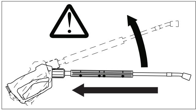
■ Injury hazard through recoil action.
The force of the recoil action may throw you off balance, and you may fall down. The spray lance may whip around and injure persons standing nearby.
Select a secure foothold position and firmly grasp the handgun.
Never wedge the handgun trigger in the open position.
■ Injury hazard through defective hose coupling.
Check hose coupling daily for tightness and absence of leakage.

Danger!
■ Health hazard posed by toxic substances.
Do not spray clean the following materials, because substances known to pose a risk to human health may be swirled up:
- Materials containing asbestos
- Materials that could possibly contain toxic substances hazardous to human health.
■ Poisoning Hazard.
Chemical burn hazard.
Fire hazard.
Protect cleaning detergent storage against access by unauthorised persons. Observe all safety instructions for cleaning detergents.
5. Noise Protection
The sound level of the plant is approximately 80 dB (A). Because of this, the wearing of a hearing protection aid at the place where it is installed is not stipulated.
However, at the workplace proper, (i.e., handgun) a noise hazard must be assumed to be present under normal circumstances (pursuant to Regulation VBG 87). Accordingly, suitable hearing protection must be worn while working in noise-polluted areas.
6. Workplaces
The pump unit, where the system is only switched on and off. Other workplaces are, depending on the system installation, at the accessory devices (spraying devices) which are connected to the taps.
7. Authorised Operators
The operation of the system is restricted to persons over the age of 18 who have been properly instructed. An exception is made with youths over age 16 who need to operate the system as part of their training, and if such use of the system is duly supervised (Regulation VBG 87).
Additional local ordinances must be observed.
The system operator is responsible for third persons within the working area.
The areas of responsibility covering the various operator functions on the machine must be precisely delineated and stringently observed.
Overlapping areas of competence present a safety risk.
The system owner is responsible for:
■ making the Operating Instructions available to the system operator
■ ensuring that the operator has read and understood the Operating Instructions.
8. Personal Protective Equipment

When cleaning resonating components, hearing protection must be worn to prevent hearing loss.
■ For protection against spray-water, water repellent protective clothing must be worn.
9. Safety Measures on the Installation Site

Danger!
Risk of injury from the system falling down. The wall attachment must be carried out professionally. When doing so consideration must be given to the load-bearing capability of the wall.
10. Protective Devices
■ The system is shut down by the emergency-OFF master switch.
■ Protection against contact with all unit parts which are hot, with the exception of the water inlet and high-pressure outlet, is provided by the housing.
11. Emergency drill
■ Turn unit switch to position "0"
■ Close water inlet.
■ Release water pressure by opening a high-pressure spray gun.
12. Guidelines and Regulations
In the Federal Republic of Germany the operation of this system is subject to the Regulations for Liquid Spraying Devices (VBG ZH 1/406), published by the Principal Organisation of the Commercial Employers' Liability Insurance Association. The guidelines may be ordered from Carl Heymann Verlag KG, Luxemburger Strasse 449, D-50939 Cologne, Germany.
- Among other requirements, the Regulations foresee a system inspection by a certified professional in intervals of no more than 12 months. The results of the inspection must be documented in writing.
- A testing log for entering the inspection results is located at the end of this manual.
- Kärcher customer service engineers qualify as certified professionals, and are authorised to carry out the aforementioned inspection.
■ Also applicable are the (German) Regulations governing liquid spraying devices, VBG 87, and the Ordinance on Hazardous Substances VBG ZH 1/220 (Gef-StoffV).
■ Please further observe any local regulations governing electrical connection, and water and waste-water drainage connections. Inquiries about these regulations can be made at the relevant supply company.
■ Connection work may be undertaken only by Kärcher Customer Service or by authorised professional personnel under observance of these regulations.
13. Proper Use of the Equipment
This system feeds water under high pressure to downstream high-pressure cleaning devices. As required, cleaning agent is drawn in and mixed with the water.
Fixed installation of the system is in a dry room protected from sub-zero temperatures. An on-site installation may be no warmer than 40 °C. Distribution of the water under high pressure takes place via a fixed-installation pipes.

Important!
Only clean water may be used as a high-pressure medium. Water contamination of any kind would cause premature component wear or lead to deposits within the system.
Requirements in water quality:
| pH value | 6.5...9.5 |
| electrical conductivity | under 2000 μS/cm |
| settling solids | under 0.5 mg/l * |
| filtering solids (particle size under 0.025 mm) | under 20 mg/l |
| hydrocarbons | under 20 mg/l |
| chloride | under 300 mg/l |
| calcium | under 85 mg/l ** |
| total hardness | under 15°dH ** |
| iron | under 0.5 mg/l |
| manganese | under 0.05 mg/l |
| copper | under 0.02 mg/l |
| free of bad smells | |
| * test volume 1l / settling time 30 minutes |
| ** at higher values, decalcifying measures are necessary |
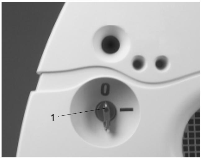
1. Operator controls
natural_image
Close-up of a white electronic device's internal component with a key inserted into a circular opening, labeled '1' (no text or symbols beyond the number)


| Push button | Function |
| 1 | Emergency-OFF master switch | switches the system on and off,starts the system-available time,serves simultaneously as Emergency-STOP switch |
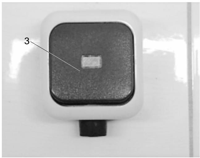
| 2 | Metering valve for detergent | for adjusting the concentration of detergent in the water jet |
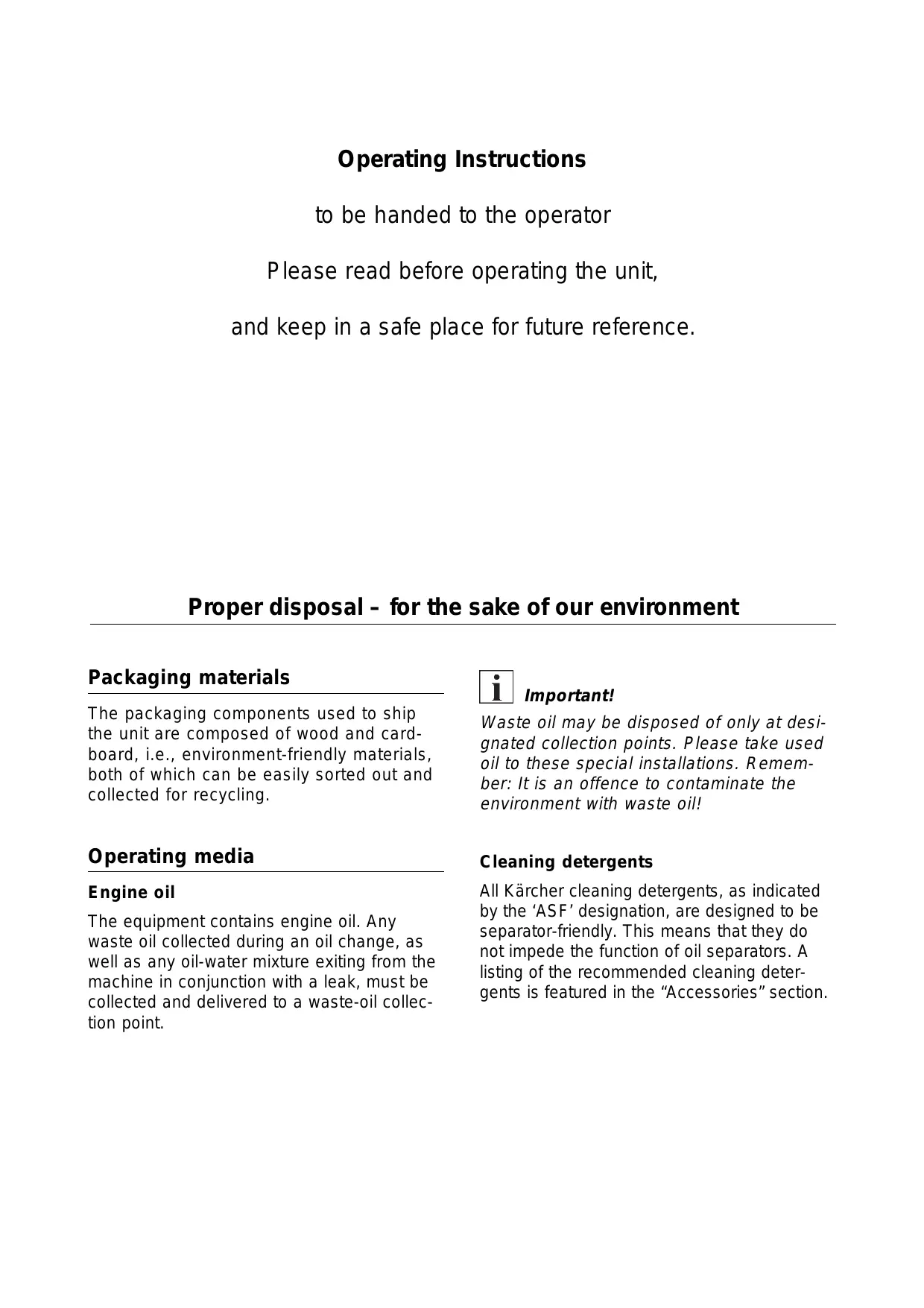
| 3 | Remote unlock (option) | starts the system after system-available time has expired |
2. Switching off in case of emergency
■ Turn Emergency-Off master switch to position "0"
■ Close water inlet
■ Reduce water pressure by operating the handgun
3. Operation at the pump unit
Initial operation
■ Open water inlet
■ Set Emergency-Off master switch to position "I"
■ Press start button
■ Carry out cleaning process.
After running time
The pump stops if there is a pause during cleaning of more than 1 second. The adjustable “available” time is started simultaneously.

Caution!
Risk of damage. With emptied detergent reservoir the pump draws air. After closing of the hand gun the automatic switch-off of the pump is disturbed. Longer pump running time without water consumption causes pump damage. Therefore level of detergent reservoir should be checked regularly and refilled.
"Available" time
The system starts automatically within the “available” time as a result of the fall in pressure when the handgun is opened. The system-available time is adjustable between 2 and 8 minutes.
Restoring the availability time
■ Switch off master switch and switch it on again, or press the remote-unlock button
4. Adjustment settings
The adjustment settings described below are made at the initial start-up of the unit by the service engineer. Changes to them are undertaken as follows.

Danger!
Danger of electric shock. Before opening the control cabinet, turn off the master switch and secure it against being turned on.
Open unit cover
■ Lift up cover at the front edge.
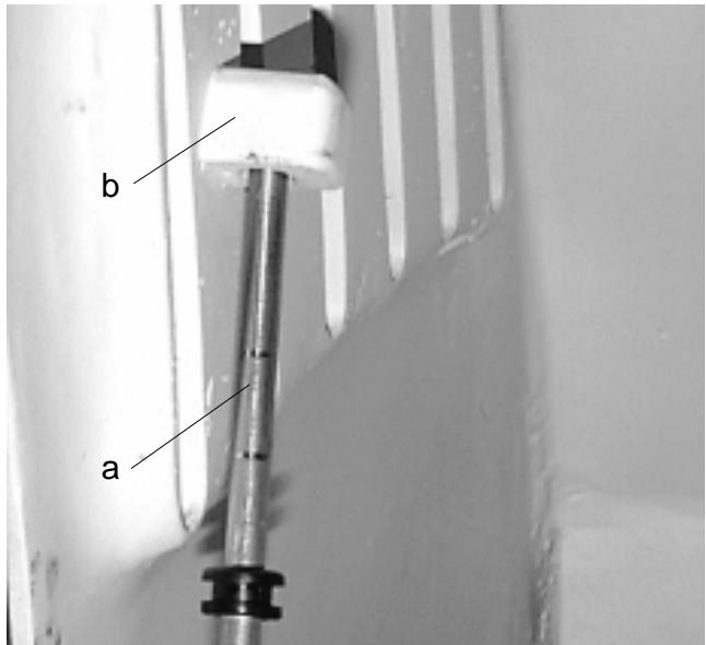
■ Swing up support (a) and secure end of support from slipping by inserting it in the holding device (b).
Close unit cover

Caution!
Danger of getting hands trapped. When closing the unit cover arrange the hands in such a way that they cannot get trapped between the unit cover and the lower part of the housing.
■ Hold on to support (a).
■ Raise unit cover slightly.
■ Fold support down and lay it down.
■ Swing unit cover down.
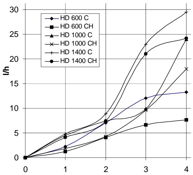
Detergent dosage
Detergent is drawn in directly on the suction side by the high-pressure pump out of an external detergent reservoir.
The metering amount is set at the detergent metering valve (2) in the unit. The set value corresponds to the proportional amount of detergent in the jet spray.
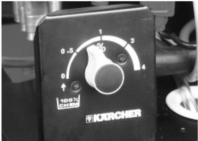

Important!
To vent the detergent suction line, turn the metering valve to position 4 %.
For faster venting compress the suction hose at the float tank while pump is running.
The following graphs show the amount of detergent drawn in for the positions of the metering valve.
line
| x | HD 600 C | HD 600 CH | HD 1000 C | HD 1000 CH | HD 1400 C | HD 1400 CH |
|---|---|---|---|---|---|---|
| 0 | 0 | 0 | 0 | 0 | 0 | 0 |
| 1 | 2 | 1 | 4 | 5 | 4 | 4 |
| 2 | 7 | 4 | 8 | 9 | 8 | 7 |
| 3 | 12 | 6 | 10 | 12 | 23 | 21 |
| 4 | 13 | 7 | 18 | 24 | 30 | 24 |
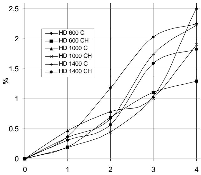
line
| Time | HD 600 C | HD 600 CH | HD 1000 C | HD 1000 CH | HD 1400 C | HD 1400 CH |
|------|----------|-----------|-----------|------------|-----------|------------|
| 0 | 0.0 | 0.0 | 0.0 | 0.0 | 0.0 | 0.0 |
| 1 | 0.3 | 0.2 | 0.4 | 0.3 | 0.3 | 0.3 |
| 2 | 1.2 | 0.7 | 0.8 | 0.5 | 0.6 | 0.6 |
| 3 | 2.0 | 1.1 | 1.7 | 1.0 | 1.6 | 1.6 |
| 4 | 2.5 | 1.3 | 2.5 | 1.9 | 2.2 | 1.8 |
"Available" time
The system-available time is adjusted by means of the potentiometer (a) on the electronic control circuit.
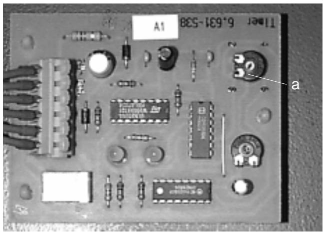
The time can be adjusted between 2 and 8 minutes. A simple scale is printed on the printed circuit board with reference values.
Softener accessory kit (optional)
■ Enquire about the local hardness of water from the supply company responsible or determine it using a hardness tester (Order no. 6.768-004).
■ The adjustment is made at the rotary potentiometer (b) on the softener PCB.
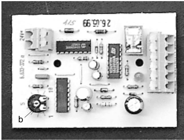
The correct setting can be taken from the table.
| Water hardness(°dH) | 5 | 10 | 15 | 20 | 25 |
| Scale | 8 | 7 | 6 | 5 | 4.5 |
| Pause time(Sec.) | 50 | 40 | 31 | 22 | 16 |
Example
For a water hardness of 15^ dH, set scale value 6. This gives a pause time of 31 seconds, i.e. the solenoid valve opens every 31 seconds (short, audible click).
5. Stopping the System
■ Turn the system's Emergency-STOP master switch to the 0 (OFF) position.
■ Shut OFF the water supply.
■ Open the handgun until the water pressure has dissipated.
■ Using the locking feature, secure the handgun against being opened accidentally.
6. Frost Protection
The water-bearing parts of the system must be protected from freezing, since they could otherwise be destroyed. If the system is to be operated also in freezing temperatures, it must be installed in a frost-free location. Outdoor water lines must be frost-protected (i.e., through insulation or line heaters, or by draining during freezing temperatures).
7. System Shut-Down
If a system is to be shut down during cold periods, it must first be flushed with an antifreeze solution. As a rule, antifreeze products also contain corrosion inhibitors.
1. Flow diagram
flowchart
graph TD
    A["6"] --> B["12"]
    B --> C["5"]
    C --> D["9"]
    D --> E["7"]
    E --> F["1"]
    F --> G["3"]
    G --> H["4"]
    H --> I["11"]
    I --> J["2"]
    J --> K["10"]
    style A fill:#f9f,stroke:#333
    style B fill:#ccf,stroke:#333
    style C fill:#cfc,stroke:#333
    style D fill:#fcc,stroke:#333
    style E fill:#cff,stroke:#333
    style F fill:#ffc,stroke:#333
    style G fill:#cfc,stroke:#333
    style H fill:#fcc,stroke:#333
    style I fill:#ffc,stroke:#333
    style J fill:#cfc,stroke:#333
    style K fill:#fcc,stroke:#333
1 High-pressure pump
2 Pressure switch high pressure
3 Pressure switch low pressure
4 Flow control
5 Float tank
6 Water inlet
7 Detergent metering, manual
9 Precompression pump hot water (only in HD xxxx CH)
10 High-pressure outlet
11 Pressure gauge (operating pressure)
12 Accessory kit, softener (option)
2. Description of functions
Full pumping capacity
On take-off of the entire flow rate, the water flows via
■ water inlet (6),
■ float tank (5),
■ precompression pump hot water (9) (only in HD xxxx CH),
■ high-pressure pump (1),
■ to high-pressure outlet (10).
Part take-off
If only part of the water capacity fed by the pump is required, the remaining volume flows via the
■ flow control (4) back
■ to the suction side of the high-pressure pump (1).
Detergent
Detergent is drawn in by the high-pressure pump (1) via the manual detergent metering device (7)
Automatic pump start
If the system pressure drops during the available time owing to the opening of a consuming device, then the high-pressure pressure switch (2) starts the pump.
Automatic switch-off
If the water flow in the flow control device (4) rises as a result of little or no water take-off, the pressure also rises at the low-pressure pressure switch (3). If the pressure exceeds a threshold value, the switch-off procedure begins:
■ After one second the pumps stops and the “available” time begins.
If a take-off of water happens inside the "available" time, the pump starts up again.
■ When the system-available time has expired, the system is set in operation by switching off the Emergency-Stop master switch and switching it on again, or by pressing the remote unlock button (option).
| | HD 600 C1.211-101 | HD 600 CH1.211-201 | HD 600 C1.211-102 | HD 600 CH1.211-202 | HD 600 C1.211-103 | HD 600 CH1.211-203 | HD 600 C1.211-104 | HD 600 CH1.211-204 |
| Type of current | | 3~. 50 Hz | 3~. 50 Hz | 3~. 60 Hz | 3~. 60 Hz |
| Voltage | V | 400 | 230 | 230 | 460 |
| Rated power consumption max.(at 20° water temperature) | kW | 3.8 |
| Electrical supply line | mm2 | 4 x 2.5 |
| External pre-fusing | A delayed-action | 16 |
| Flow rate | l/h | 580 |
| Operating pressure | bar | 160 |
| Max. allowable operating pressure | bar | 165 |
| Water inlet | l/h | 600 |
| Max. supply temperature | °C | 60 | 80 | 60 | 80 | 60 | 80 | 60 | 80 |
| Flow pressure min. | bar | 2 |
| Flow pressure max. | bar | 6 |
| Inside diameter feed line | mm | DN 13 |
| Engine oil, Order no. | | 6.288-061 |
| Engine oil, filling capacity | l | 0.75 |
| Length | mm | 680 |
| Width | mm | 600 |
| Height | mm | 470 |
| Weight (empty) | kg | 76 | 80 | 76 | 80 | 76 | 80 | 76 | 80 |
| Sound level | dB (A) | 72 |
| | HD 1000 C 1.042-101 | HD 1000 CH 1.042-201 | HD 1000 C 1.042-102 | HD 1000 CH 1.042-202 | HD 1000 C 1.042-103 | HD 1000 CH 1.042-203 | HD 1000 C 1.042-104 | HD 1000 CH 1.042-204 |
| Type of current | | 3~.50 Hz | 3~.50 Hz | 3~.60 Hz | 3~.60 Hz |
| Voltage | V | 400 | 230 | 230 | 460 |
| Rated power consumption max.(at 20° water temperature) | kW | 5.7 |
| Electrical supply line | mm2 | 4 x 2.5 |
| External pre-fusing | A delayed-action | 16 | 20 | 20 | 16 |
| Flow rate | l/h | 950 |
| Operating pressure | bar | 150 |
| Max. allowable operating pressure | bar | 155 |
| Water inlet | l/h | 1000 |
| Max. supply temperature | °C | 60 | 80 | 60 | 80 | 60 | 80 | 60 | 80 |
| Flow pressure min. | bar | 2 |
| Flow pressure max. | bar | 6 |
| Inside diameter feed line | mm | DN 13 |
| Engine oil, Order no. | | 6.288-061 |
| Engine oil, filling capacity | l | 0.75 |
| Length | mm | 680 |
| Width | mm | 600 |
| Height | mm | 470 |
| Weight (empty) | kg | 81 | 85 | 81 | 85 | 81 | 85 | 81 | 85 |
| Sound level | dB (A) | 72 |
| External pre-fusing | A delayed-action | 16 | 20 | 20 | 16 |
| Flow rate | l/h | 1400 |
| Operating pressure | bar | 120 |
| Max. allowable operating pressure | bar | 125 |
| Water inlet | l/h | min. 1400 |
| Max. supply temperature | °C | 60 | 80 | 60 | 80 | 60 | 80 | 60 | 80 |
| Flow pressure min. | bar | 2 |
| Flow pressure max. | bar | 6 |
| Inside diameter feed line | mm | DN 13 |
| Engine oil, Order no. | | 6.288-061 |
| Engine oil, filling capacity | l | 0.75 |
| Length | mm | 680 |
| Width | mm | 600 |
| Height | mm | 470 |
| Weight (empty) | kg | 81 | 85 | 81 | 85 | 81 | 85 | 81 | 85 |
| Sound level | dB (A) | 72 |
- HD 1400 C(H)
4. Dimension diagram
1. System overview
natural_image
Close-up of industrial mechanical components with pipes and a labeled component (CHEM) on a base, no readable text or symbols beyond the label.
1 Pressure gauge
2 Oil reservoir
3 Vibration damper
4 Strainer water inlet
5 Threaded oil-drain plug
6 High-pressure pump
7 Precompression pump (only HDxxxxCH)
8 Pressure switch, high pressure
9 Pressure switch, low pressure
10 Metering valve for detergent, manual
12 Float tank
2. Notes on maintenance
The basis of a reliably operating system is regular maintenance in accordance with the following maintenance schedule.
Use only manufacturer's original spare parts or parts recommended by him, such as
■ Spare parts and wearing (consumable) parts
■ Accessory parts
■ Operating media
■ Cleaning media.

Danger!
Danger of accident when carrying out maintenance work on the system. For all maintenance tasks:
■ Turn off water supply by closing the water tap.
■ Injury hazard through exiting water jet of high-pressure or high-temperature water. Release system pressure before performing work on system components. In the case of hot-water operation, allow unit to cool before commencing work.
■ Electric shock hazard.
Switch OFF and secure master switch before commencing work on the system.
Who is allowed to carry out maintenance tasks?
Operator
Tasks which are given the designation "Operator" may be carried out only by instructed personnel, who are able to operate the high-pressure systems safely and maintain them.
■ Customer Service
Tasks which are given the designation "Customer Service" may be carried out only by Kärcher Customer Service engineers.
Maintenance contract
To ensure that your system operates reliably, we recommend that you take out a maintenance contract. Please take the matter up with your responsible Kärcher Customer Service.
- Maintenance Schedule
| Interval | Procedure | Subject Assembly | Activity | By whom |
| Daily | Check handgun | All handguns | Check whether handgun closes properly. Check function of safeguard against inadvertent operation. Replace defective handguns. | Operator |
| Check fill level | Detergent reservoir, accessory kit softener (optional) | Check fill level, if necessary fill up | Operator |
| Check high-pressure hoses | Outlet lines & hoses leading to workstations | Check hoses for damage. Replace defective hoses immediately. Accident Hazard! | Operator |
| Weekly, or after 40 operating hours | Check system for leaks | Entire system | Check pump and line system for leaks. If oil is present in the drip pan under pump, of if a leak exceeds 10 drops of water per minute, call customer service immediately. Keep weep holes unblocked. | Operator/ Customer Service |
| Check oil quality | Pump | If the oil appears milky, it must be changed. In this case it is recommended to change the pump oil seal also. (Customer service.) | Operator/ Customer Service |
| Check oil level | Pump | If required, top up with oil (part no. 6.288-061). | Operator |
| Check working pressure | Manometer | Check system water pressure (pressure gauge). If pressure is too high or too low, investigate and remedy the cause (see also the section on Trouble Shooting). | Operator |
| Check hose quick-couplings | Hose quick-couplings between system tap and high-pressure hose to handgun. | Pump must be running. Check for leakage in tandem and individual operation. Connect clutch and check clutch locking function. Replace defective clutches. | Operator Customer Service |
| Check dashpot | Vibration damper | A defective dashpot is readily identifiable through increased pump vibration. Replace defective dashpot. | Operator Customer Service |
| monthly, or after 200 operating hrs. | Clean strainer | Strainer, water inlet | Switch off unit, turn off water, bleed pressure. Dismantle strainer and clean it. | Operator |
| Check float valve | Float reservoir | When the float valve is closed, it is not possible for water to escape at the overflow. | Operator |
| Check automatic switching on | Pressure switch | Pump is stands still as there is no take-off of water. Open handgun. If pressure in the high-pressure network sinks below 30 bar, the pump must switch on. | Operator |
| Tighten hose clamps | All hose clamps in/on the unit | Tighten hose clamps with torque wrench. Torque: 28 mm nominal diameter: 2 Nm 29 mm nominal diameter: 6 Nm | Operator |
| Semi-annually, or after 1000 operating hours | Oil change | HD-Pumpe | CAUTION! Hot Oil Scalding Hazard. Prior to oil change, allow pump to cool for 15 minutes. Drain oil and fill with 0.75 litres of oil, Part No. 6.288-061. Do NOT use alternate oil products! | Operator |
| Check unit for lime deposits | Entire water system | Functional faults on valves or pumps may indicate calcification. Use procedures outlined on the following pages. | Operator trained in decalcificat procedures |
| Tighten terminal strips | Control cabinet | Tighten all terminal strips of components master mains power circuit. | Electrician |
| Annually | Safety check | Entire system | Safety inspection pursuant to guidelines covering liquid spraying devices. Refer to section A.12. | Expert/Customer service |
| Tighten hose clamps | All hose clamps in/on the unit | Tighten hose clamps with torque wrench. Torque: 28 mm nominal diameter: 2 Nm 29 mm nominal diameter: 6 Nm | Operator |
4. Oil change

Danger!
Risk of getting burnt from hot oil and hot system components. Let pump cool down for 15 minutes before making oil change.

Important!
Used oil may be disposed of only at the collecting points designated for this purpose. Please hand in used oil resulting from the oil change at such a place. Pollution of the environment with waste oil is a punishable offence.
Oil types and oil quantities: see Technical Data.
Carry out the oil change as follows:
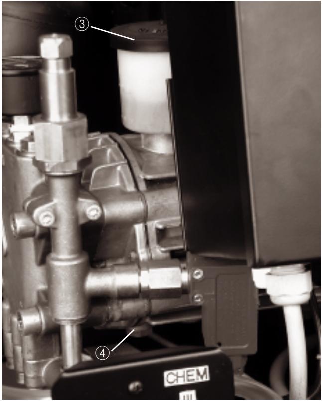
■ Hold container for used oil ready.
■ Remove cover of oil reservoir ③.
■ Screw out threaded oil-drain plug ④ and catch used oil.
■ Screw in threaded oil-drain plug ④.
■ Pour in new oil slowly up to position "Max" on oil reservoir.
■ Put on cover of oil reservoir ③.
■ Convey used oil to the designated collection point.
5. Decalcification

Danger!
Explosion hazard through flammable gases! Smoking is prohibited when carrying out decalcification procedures. Ensure adequate ventilation.

Caution!
Acid hazard!
Protective goggles and gloves must be worn.
Lime deposits throughout the water lines of the high-pressure system create increased pipe-run resistance and may result in the failure of calcified components.
According to official regulations, only approved boiler scale dissolvants (de-scaling acid) with test mark may be used.
For scale removal in the high-pressure system, the use of KÄRCHER scale dissolvants should be given preference (RM 100 ASF, hydrochloric acid-free, part no. 6.287-008, or RM 101 ASF, containing hydrochloric acid, part no. 6.287-013).
These products are balanced for use in conjunction with the materials present throughout the system. After decalcification we recommend neutralising the remaining acid residues by flushing the system with an alkaline solution (pH value 7–8).
The instructions for use and accident prevention regulations (dilution according to label specifications), and in particular VBG1, §4, 14, and 44–47 must be observed.
Proceed as follows:
Begin by decalcifying the float reservoir:
Close water supply.
Remove the float reservoir lid. Remove the hose connecting the pump suction side with the float reservoir, pump side. Block the free end of the hose. Pour in 7-percent de-scaling solution. After the conclusion of decalcification, remove all scale residues from the reservoir!
Decalcifying high-pressure system:
Disconnect high-pressure hose from water supply inlet and hang into float reservoir. Next, use the decalcifying acid solution pre-mixed in the float reservoir for short-term system operation in circulation (idle pressure) mode. Allow chemicals to activate, and conclude by flushing the system.

Danger!
Risk of accident when carrying out tasks on the system
For all tasks:
■ Turn off water supply by closing the water tap.
■ Risk of injury from water jet which may also be hot.
Before carrying out work on the system, bleed pressure and wait until the system has cooled down.
■ Danger of electrical shock. Before carrying out work on the system, switch off master switch and secure it.
Who is allowed to remedy faults?
Operator
Tasks which are given the designation "Operator" may be carried out only by instructed, skilled personnel. Instructed, skilled personnel are those who are able to operate the high-pressure systems safely and maintain them.
Electricians
Tasks which are given the designation "Skilled electrician" may be carried out only by persons who have a professional training in electrical engineering
■ Customer Service
Tasks which are given the designation "Customer Service" may be carried out only by Kärcher Customer Service engineers.
| Problem | Possible Cause | Remedy | by whom |
| High-pressure pump fails to come up to pressure | Leaking suction-side tubing system | Check fastener and hose connections | Operator |
| Water starvation | Correct the cause | Operator |
| Leaking high-pressure hose | Replace hose | Customer Service |
| Leaking pipeline system | Overhaul | Customer Service |
| Defective flow control | Check flow control, overhaul unit | Customer Service |
| Defective valve in pump | Replace valves | Customer Service |
| Pronounced pump knock, pressure gauge pointer oscillates | Defective dashpot | replace | Operator |
| Pump is drawing air | Check suction line | Operator |
| Detergent reservoir empty | Refill detergent reservoir | Operator |
| Water inlet temperature too high | Reduce water temperature | Operator |
| Water inlet blocked | Clean strainer at water inlet, check water inlet | Operator |
| Defective valve seat or valve spring | Replace as required | Customer Service |
| Defective or calcified precompression pump (only in HD xxxx CH) | Check precompression pump | Operator |
| Water jet is uneven | Nozzle of handgun blocked | Clean nozzle | Operator |
| Water supply not sufficient | Check water supply | Operator |
| No drawing-in of detergent | Dosage set at too little | Set dosage higher | Operator |
| Suction filter in detergent reservoir dirty | Clean suction filter | Operator |
| Detergent suction hose leaking | Replace suction hose | Customer Service |
| Metering valve cleaning agent, manual, defective | Check metering valve, replace if necessary. | Customer Service |
| Problem | Possible cause | Remedy | by whom |
| System does not start up when switching on or when pressing the remote unlock button (option) | Pressure switch defective | Replace pressure switch | Customer Service |
| Motor protection switch has triggered owing to excess current or failure of one phase of the power supply system | Check voltage of the three phases | Customer Service / Electrician |
| Motor protection switch falsely set | Set in accordance with circuit diagram | Customer Service / Electrician |
| Site power supply interrupted | switch on | Operator |
| Emergency-STOP master switch off | switch on | Operator |
| Motor protection switch for control system and precompression pump has been triggered | check | Customer Service / Electrician |
| Control-circuit fuse on transformer defective | replace, check cause | Customer Service / Electrician |
| PCB defective | replace, check | Customer Service |
| Pump starts during available time but not by opening the handgun | Pressure switch or cable to pressure switch defective | replace | Customer Service |
| System does not switch off. | Pump draws air from empty detergent reservoir | Refill detergent reservoir, remove air from suction hose | Operator |
| Pressure switch for low pressure defective | Replace pressure switch | Customer Service / Electrician |
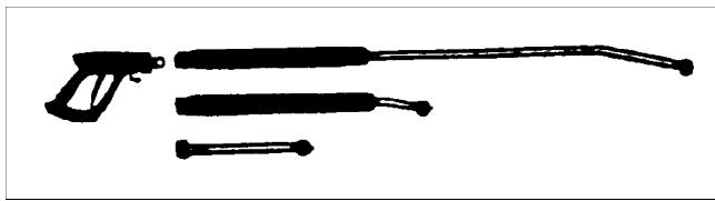
Handguns with different spray lances
Dependent on the cleaning application, different spray lance extensions are required, ranging from 250 mm for one-hand operation to 2040 mm for cleaning high objects.
natural_image
Silhouette of four different types of weapons or tools, including a pistol and three elongated sticks (no text or symbols visible)
Nozzles
Several nozzles with different spray angles are available for the system. The nozzles are mounted on the spray lance by means of a union nut, and are easily changed.
| Design-ation | Spray angle | Order No. 2.883- |
| HD 600 C (H) | 25036 | 25° | -821 |
| HD 1000 C(H) | 15060 | 15° | -391 |
| 25060 | 25° | -402 |
| HD 1400 C(H) | 25100 2 x 25050 | 25° | -408 2 x -399 |
Force of recoil from the handgun when using these nozzles:
| HD 600 C | 160 bar | 28 N |
| HD 1000 C | 150 bar | 30 N |
| HD 1400 C | 120 bar2 x 120 bar | 35 N2 x 28 N |
The spraying device (i.e., handgun) is connected by means of an in-line quick-coupling.
Accessory kit, Stand
Used for setting up the pump unit when wall-mounting is not possible for technical or architectural reasons.
Accessory kit, Softener
As a protection against calcification when operating in hot-water mode with hard water. Meters softener into the water. The metered amount can be adapted to the degree of hardness of the water.
Cleaning detergents
Cleaning detergents facilitate any cleaning task. A selection of cleaning agents is listed in the table on the following page. When using detergents it is essential to observe the instructions supplied on the product labels.
The following types of cleaning detergents must not be used with this system:
● Detergents containing nitric acid
● Detergents containing active chlorine
Using these types of detergents will result in damage to unit components.
| Area of application | Contamination type Application method | Cleaning agent | Approx. pH value 1 %-solution |
| Automotive, petrol stations, motor carriers, vehicle fleets | Dust, road grime, mineral oils (on painted surfaces) | RM 55/1000-liquid ASF **RM 22/80-powder ASFRM 81-liquid ASFRM 803-liquid ASF | slightly alkalinealkalinealkalinealkaline |
| Vehicle protection | RM 820-hot wax ASFRM 821-spray wax ASFRM 824-Super-Perlwachs ASF | neutralneutralneutral |
| Metal-working industry | Oils, greases, dust and similar contamination | RM 22-powder ASFRM 55-liquid ASFRM 81-liquid ASFRM 31-liquid ASF (heavy contamination)RM 39-liquid (with corrosion protection) | alkalineslightly alkalinealkalinestrongly alkalineslightly alkaline |
| Food processing industry | Light to medium contamination, greases/oils large surfaces | RM 55-liquid ASFRM 81-liquid ASFRM 58-liquid ASF (foaming cleanser)RM 31-liquid ASF * | slightly alkalinealkalinealkalinestrongly alkaline |
| Smoky resin | RM 33-liquid * | strongly alkaline |
| Cleaning and disinfecting | RM 32-D-liquid | alkaline |
| Disinfecting | RM 735-D-liquid | alkaline |
| Lime, mineral deposits | RM 25-liquid ASF *RM 59-liquid ASF (foaming cleanser) | strongly acidicacidic |
| Sanitary installations | Lime, urinal deposits, soaps, etc. | RM 25-liquid ASF (basic cleaning)RM 59-liquid ASF (foaming cleanser)RM 68-liquid ASF | strongly acidicacidicacidic |
* = for short-term use only. Two-step method. Flush with clean water.
** = ASF = abscheidefreundlich
AUTHORISED PROFESSIONAL PERSONNEL ONLY
1. Placement
The system must be installed in dry indoor surroundings free from explosion hazard. The components shall be placed on firm and level ground, and the system must be easily accessible for the purpose of maintenance procedures. The room temperature must not exceed 40 °C.
Possible ways in which the unit can be set up are as follows:
■ Mounted on the wall
■ Set up on the ground using the Stand accessory kit (optional)
If wall mounting is used, the wall should be tested for its load-bearing capability. The supplied mounting materials are suitable for walls made of concrete or solid brick with a wall thickness from 11.5 cm. Information on mounting on other types of wall construction can be gained from “Planning manual HD-ST”.
(For drill-hole layout see specifications table).
If the unit is set up using the Stand accessory kit, the procedure is described in the supplied assembly instructions.

Danger!
Risk of injury from the water jet or parts flying off.
The screw unions of all connecting hoses and pipelines must be tight. Use only undamaged and manufacturer-recommended screw unions and high-pressure hoses.
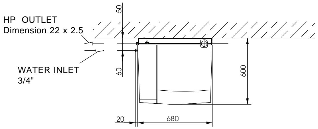
2. Connections
The water connection, the high-pressure network and the electrical connections may be carried out only by authorised skilled personnel in compliance with local regulations. The water supply and the power connection must be made available for continuous operation. The prescribed connected values can be seen in the technical data. The water quality must meet the requirements as specified in section “A.13 Proper use of the equipment”.
In Germany the following regulations apply:
■ VDMA Einheitsblatt 24416 directive "Festinstallierte Hochdruck Reinigungssysteme" (Fixed-installation high-pressure cleaning systems)
■ VDE regulations
■ Local power-supply company regulations
The water supply must be equipped with a shutoff valve, and must be connected with the high-pressure by means of a flexible high-pressure hose. Insufficient supply line cross section or insufficient admission pressure will result in water starvation.
In the event of excessive admission pressure or the occurrence of pressure peaks in the mains network, the installation of a pressure regulator upstream of the system is mandatory.
A water drain must be present at the installation site.
3. High-pressure Installation
The link between the fixed-installation pipe network and the system must be executed in the form of a flexible high-pressure hose connection.
The permanent pipe network installation must consist of as many straight runs as possible. All high-pressure tubing must be installed pursuant to regulations, using vibration-dampened strain relief and fixed pipe or tubing clamps, while allowing for longitudinal expansion/contraction due to the effects of temperature and pressure.
AUTHORISED PROFESSIONAL PERSONNEL ONLY
AUTHORISED PROFESSIONAL PERSONNEL ONLY
To keep pressure losses in the high-pressure lines as low as possible, the following recommendations should be used as mandatory guidelines:
| Flow rate | Pipeline | Hose line |
| 600 l/h | DN 15 ( 12 ") | DN 8 |
| 1000 l/h | DN 15 ( 12 ") | DN 8 |
| 1400 l/h | DN 15 ( 12 ") | DN 8 |
It should be understood that the above guidelines still require additional allowances for the overall tubing length, the number of directional changes and armatures.
4. Mounting detergent reservoirs

Danger!
Danger of being poisoned, suffering acid burns and fire hazard as a result of improper handling of detergents.
Store detergents in a place which is inaccessible to children. Be certain to observe the instructions on the packaging.
The cleaning agent reservoir should be set up in such a way that the base of the reservoir is not more than 2 m below the unit.
5. Hard-water Treatment
An over-high hardness of water ( >15^ dH) can lead to deposits and functional faults. Where hardness of water is relatively high, use the Softener accessory kit.
6. Preparations for Commissioning
■ Thoroughly rinse entire HD system Check entire HD system for correct assembly and lack of leaks.
■ Only for HD xxxx CH units: Push and secure enclosed overflow hose incl. hose clip on hose liner at float tank. Conduct hose end through the opening located in the base of the plant.
■ Complete electrical connections in accordance with the Specifications contained in the Operating Instructions.
■ Check the function of decalcifying component (if required).
- Check water supply for required delivery volume and maximum allowable temperature.
■ Check pump oil level. Remove threaded plug from oil reservoir.
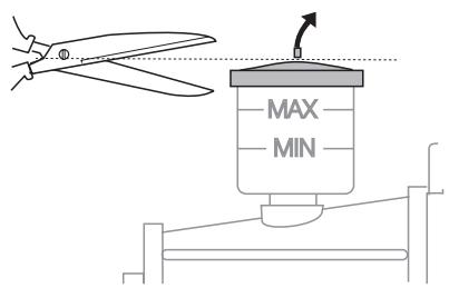
■ Before using for the first time, cut off the tip of the cover of the oil reservoir on the water pump.
■ Only for HD xxxx CH: Check direction of rotation of the precompression pump. Direction of rotation has to be in unison with the arrow on the housing.
■ Make adjustment settings as described in section B.4.
AUTHORISED PROFESSIONAL PERSONNEL ONLY
AUTHORISED PROFESSIONAL PERSONNEL ONLY
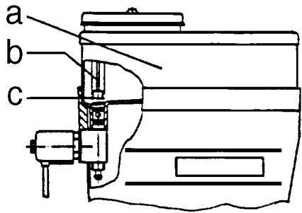
Only for accessory kit, Softener:
■ Remove the spring (c) from the cover support (b) in the liquid-softener reservoir (a).
■ Fill reservoir with Kärcher liquid softener RM 110 (Order No. 2.780-001)
AUTHORISED PROFESSIONAL PERSONNEL ONLY
AUTHORISED PROFESSIONAL PERSONNEL ONLY
7. Space Assignment Plan
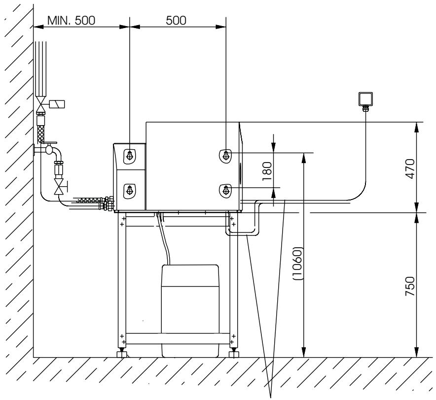
Electrical connection at side or from underneath
AUTHORISED PROFESSIONAL PERSONNEL ONLY
AUTHORISED PROFESSIONAL PERSONNEL ONLY
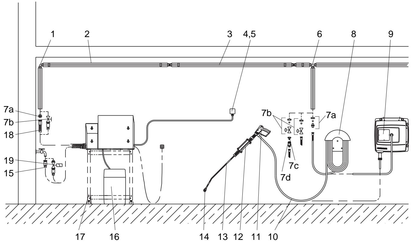
| Item | Installation material | Order no. |
| 1 | Threaded elbow joint | 6.386-356 |
| 2 | Thermal insulation | 6.286-114 |
| 3 | Piping set | 2.420-004 |
| Piping set, stainless steel | 2.420-006 |
| 4 | Remote unlock | 2.637-491 |
| 5 | Emergency-STOP switch for wall mounting | 2.744-002 |
| 6 | T threaded-joint | 6.386-269 |
| 7a | Pipe connection, brass | 2.638-180 |
| Pipe connection, stainless steel | 2.638-181 |
| 7b | Stop-cock NW 8, galvanised steel | 4.580-144 |
| Pipe connection, stainless steel | 4.580-163 |
| 7c | Quick-fitting coupling fixed piece | 6.463-025 |
| 7d | Quick-fitting coupling loose piece | 6.463-023 |
| 8 | Hose support | 2.042-001 |
| 9 | Hose reel | 2.637-238 |
| Item | Installation material | Order no |
| 10 | HP hose 10 m | 6.388-083 |
| 11 | Handgun | 4.775-012 |
| Handgun System 2000 | 4.775-282 |
| Handgun Servopress | 4.775-152 |
| 12 | Spray lance holder | 2.042-002 |
| 13 | Spray lance 1040 mm | 4.760-220 |
| Spray lance 1050 mm System 2000 | 4.760-355 |
| 14 | Nozzle mouth piece HP 601 C (H) | 2.883-821 |
| Nozzle mouth piece HP 1001 C (H) | 2.883-402 |
| Nozzle mouth piece HP 1401 C (H) | 2.883-785 |
| 15 | Water hose | 6.389-145 |
| 16 | Cleaning agent reservoir, 60 litre | 5.070-078 |
| 17 | Parts kit, floor stand, plastic coated Parts kit, floor stand, stainless steel | 2.210-042 2.210-043 |
| 18 | HP hose | 6.389-126 |
| 19 | Water inlet solenoid valve | 4.743-011 |
AUTHORISED PROFESSIONAL PERSONNEL ONLY
System Type:
Works No.
Commissioned: (date)
Inspected:
(date)....
Results/Comments:
Signature
Inspected:
(date)....
Results/Comments:
Signature
Inspected:
(date)....
Results/Comments:
Signature
Inspected:
(date)....
Results/Comments:
Signature
HD 600 C
1.211-101
1.211-102
1.211-103
1.211-104
HD 1000 C
1.042-101
1.042-102
1.042-103
1.042-104
HD 1400 C
1.212-101
1.212-102
1.212-103
1.212-104
HD 600 CH
1.211-201
1.211-202
1.211-203
1.211-204
HD 1000 CH
1.042-201
1.042-202
1.042-203
1.042-204
HD 1400 CH
1.212-201
1.212-202
1.212-203
1.212-204
natural_image
Exterior view of a Karcher industrial machine on a stand (no signage or text beyond brand name)
5.959-490
A 12578
(12/99)

natural_image
Icon of an open book with a lowercase 'i' and a number 1, symbolizing information (no text or symbols present)
natural_image
Close-up of a white electronic device's internal component with a key inserted into a circular opening, labeled '1' (no text or symbols beyond the number)


natural_image
Close-up of industrial piping and valves with a labeled component 'CHEM' (no readable text beyond label)
5
natural_image
Silhouette of four different types of firearms: a handgun, two sticks, and a pen (no text or symbols)
Buses
natural_image
Exterior view of a Karcher industrial machine on a stand (no signage or text beyond brand name)
5.959-490
A 12578
(12/99)

natural_image
Icon showing an open book with a lowercase 'i' and a number 1, enclosed in a rounded square frame (no text or symbols on the book or background)
natural_image
Close-up of a white electronic device's internal component with labeled pin (0) and number 1, no readable text or symbols beyond basic markings.


natural_image
Close-up of industrial piping and valves with a labeled component 'CHEM' (no readable text beyond label)
5
natural_image
Silhouette of four different types of weapons or tools, including a pistol and three elongated sticks (no text or symbols visible)
Ugelli
natural_image
Exterior view of a KARCHER industrial machine on a stand (no signage or text beyond branding)
5.959-490
A 12578
(12/99)

natural_image
Icon of an open book with a lowercase 'i' and a number 1, symbolizing information (no text or symbols present)
Gebruikshandleiding
natural_image
Close-up of a white electronic device's internal component with labeled pin (0) and number 1, no readable text or symbols beyond basic markings.

natural_image
Close-up of industrial mechanical components with pipes and a labeled component (CHEM) on a base, no readable text or symbols beyond the label.
natural_image
Silhouette of four different types of firearms: a handgun, two sticks, and a pen (no text or symbols)
Sproeiers
natural_image
Exterior view of a Karcher industrial machine on a stand (no signage or text beyond brand name)
5.959-490
A 12578
(12/99)

natural_image
Icon of an open book with a lowercase 'i' and a number 1, symbolizing information (no text or symbols present)
natural_image
Close-up of a white electronic device's internal component with a key inserted, labeled '1' (no text or symbols beyond basic markings)


natural_image
Close-up of industrial machinery components with visible pipes and a labeled 'CHEM' tag (no readable text beyond label)
5
natural_image
Silhouette of four different types of weapons or instruments (no text or symbols visible)
Boquillas
natural_image
Exterior view of a KARCHER industrial machine on a stand (no signage or text beyond branding)
5.959-490
A 12578
(12/99)

natural_image
Icon showing an open book with a lowercase 'i' and a number 1, enclosed in a rounded square frame (no text or symbols on the book or background)
Bruksanvisning
som overleveres den som skal betjene maskinen
natural_image
Close-up of a white electronic device's internal component with labeled pin (0) and number 1, showing no readable text or symbols beyond the label.


natural_image
Close-up of industrial mechanical components with pipes and gears, labeled 'CHEM' (no readable text beyond label)
5
natural_image
Silhouette of four different types of weapons or tools, including a pistol and three elongated sticks (no text or symbols visible)
Dyser
natural_image
Exterior view of a KARCHER industrial machine on a stand (no signage or text beyond branding)
5.959-490
A 12578
(12/99)

natural_image
Icon of an open book with a lowercase 'i' and a number 1, symbolizing information (no text or symbols present)
Bruksanvisning
natural_image
Close-up of a white electronic device's internal component with labeled pins (0 and 1), no readable text or symbols beyond the number and symbol.

natural_image
Close-up of industrial piping and valves with a CHEM label (no readable text beyond label)
5
natural_image
Silhouette of four different types of weapons or tools, including a pistol and three elongated sticks (no text or symbols visible)
Munstycken
natural_image
Exterior view of a KARCHER industrial machine on a stand (no signage or text beyond branding)
5.959-490
A 12578
(12/99)

natural_image
Icon of an open book with a lowercase 'i' and a number 1, symbolizing information (no text or symbols present)
Käyttöohje
natural_image
Close-up of a white electronic device's internal component with a key inserted into a circular opening, labeled '1' (no text or symbols beyond the number)


natural_image
Close-up of industrial piping and valve assembly with a labeled component (CHEM) on a base, no readable text or symbols beyond the label.
5
natural_image
Close-up of industrial mechanical components with labeled parts (4) and CHEM logo, no readable text or symbols beyond labels
natural_image
Silhouette of four different types of weapons or instruments (no text or symbols visible)
Suuttimet
natural_image
Exterior view of a KARCHER industrial machine on a stand (no signage or text beyond branding)
5.959-490
A 12578
(12/99)

natural_image
Icon showing an open book with a lowercase 'i' and a number 1, enclosed in a rounded square frame (no text or symbols on the book or background)
natural_image
Close-up of a white electronic device's internal component with labeled pins (0 and 1), no readable text or symbols beyond basic markings.

natural_image
Close-up of industrial mechanical components with pipes and a labeled component 'CHEM' (no readable text beyond label)
natural_image
Silhouette of four different types of firearms: a pistol, two sticks, and a nail (no text or symbols)
Форсунки
natural_image
Exterior view of a Karcher industrial machine on a stand (no signage or text beyond brand name)
5.959-490
A 12578
(12/99)

natural_image
Icon of an open book with a lowercase 'i' and a number 1, symbolizing information (no text or symbols present)
Instrukcja obsługi
wręczyć obsłudze
natural_image
Close-up of a white electronic device's internal component with a key inserted into a circular opening, labeled '1' (no text or symbols beyond the number)


natural_image
Close-up of industrial piping and mechanical components, no visible text or symbols
natural_image
Silhouette of four different types of firearms: a pistol, two sticks, and a nail (no text or symbols)
Dysze