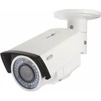
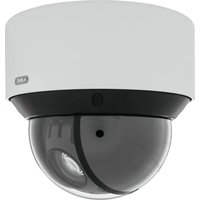
HDCC61510 - Surveillance Camera ABUS - Free user manual and instructions
Find the device manual for free HDCC61510 ABUS in PDF.


| Product type | Indoor/outdoor surveillance camera |
| Resolution | 1080p Full HD (1920x1080 pixels) |
| Viewing angle | 120° (diagonal) |
| Night vision | Yes, up to 30 meters (built-in IR LEDs) |
| Protection rating | IP67 (waterproof, weather resistant) |
| Power supply | 12 V DC / PoE (Power over Ethernet) |
| Power consumption | 6 W (max) |
| Dimensions (L x W x H) | 150 x 120 x 100 mm |
| Weight | 500 g |
| Operating temperature | -20°C to +50°C |
| Connectivity | BNC (HD-TVI), Ethernet RJ45, audio output |
| Motion detection | Yes, built-in with programmable zones |
| Recording | Requires a DVR or NVR recorder (not included) |
| Maintenance and cleaning | Clean the lens with a soft dry cloth; check cables periodically |
| Security | Password protection, video stream encryption |
| Spare parts | Available: cables, brackets, power supply (contact ABUS customer service) |
| Repairability | Repair possible by a certified technician; spare parts available |
| Warranty | 2 years (standard ABUS) |
Frequently Asked Questions - HDCC61510 ABUS
User questions about HDCC61510 ABUS
0 question about this device. Answer the ones you know or ask your own.
Ask a new question about this device
Download the instructions for your Surveillance Camera in PDF format for free! Find your manual HDCC61510 - ABUS and take your electronic device back in hand. On this page are published all the documents necessary for the use of your device. HDCC61510 by ABUS.
USER MANUAL HDCC61510 ABUS
natural_image
Technical line drawing of a mechanical assembly or enclosure (no text or symbols)D Bedienungsanleitung
GB User manual
F Manuel utilisateur
NL Gebruikershandleiding
DK Brugerhåndbog
PL Instrukcja obsługi
RU Инструкция по эксплуатации
| D | Diese Bedienungsanleitung enthält wichtige Hinweise zur Inbetriebnahme und Handhabung.Achten Sie hierauf, auch wenn Sie dieses Produkt an Dritte weitergeben.Heben Sie deshalb diese Bedienungsanleitung zum Nachlesen auf!Eine Auflistung der Inhalte finden Sie im Inhaltsverzeichnis mit Angabe der entsprechenden Seitenzahlen auf Seite 7. | DK | Denne manual hører sammen med dette produkt. Den indeholder vigtig information som skal bruges under opsætning og efterfølgende ved service. Dette skal huskes også når produkter gives videre til anden part. Læs derfor denne manual grundigt igennem også for fremtiden.Indholdet kan ses med sideanvisninger kan findes i indekset på side 86. |
| GB | These user manual contains important information for installation and operation. This should be also noted when this product is passed on to a third party.Therefore look after these operating instructions for future reference!A list of contents with the corresponding page number can be found in the index on page 24. | PL | Niniejsza instrukcja obsługi zawiera ważne wskazówki dotyczące uruchamiania i obsługi. Pamiętaj o tym, także przekazując produkt osobie trzeciej. Zachowaj instrukcję do wykorzystania w przyszłości!Wykaz treści znajdziesz w spisie treści z podaniem odpowiednich liczb stron na stronie 91. |
| F | Ce mode d'emploi appartient à de produit. Il contient des recommandations en ce qui concerne sa mise en service et sa manutention. Veuillez en tenir compte et ceci également lorsque vous remettez le produit à des tiers. Conservez ce mode d'emploi afin de pouvoir vous documenter en temps utile!Vous trouverez le récapitulatif des indications du contenu á la table des matières avec mention de la page correspondante á la page 40. | RU | Данная инструкция по эксплуатации содержит важные указания по вводу в эксплуатацию и обращению с продуктом. Примите это во внимание, также при передаче продукта в пользование третьим лицам.По этой причине сохраните данную инструкцию для повторного прочтения!Вся информация отражена в Содержании с указанием соответствующих номеров страниц на Странице 110. |
| NL | Deze gebruiksaanwijzing hoort bij dit product. Er staan belagrijke aanwijzingen in betreffende de ingebruikname en gebruik, ook als u dit product doorgeeft aan derden. Bewaar deze hendeiding zorgvuldig, zodat u deze later nog eens kunt nalezen!U vindt een opsomming van de inhoud in de inhoudsopgave met aanduiding van de paginanummers op pagina 57. | ||
HDCC61510

natural_image
Technical line drawing of a mechanical assembly or enclosure (no text or symbols)Bedienungsanleitung
Version ☐☐/2015
CE
natural_image
Technical line drawing of a mechanical device with a vertical support structure and mounting bracket (no text or symbols)6. Bildschirmmenü
natural_image
Technical line drawing of a mechanical assembly or enclosure (no text or symbols)User manual
Version ☐☐/2015
CE
English translation of the original German user manual. Retain for future reference.
Introduction
Dear customer,
Thank you for purchasing this product.
This device complies with the requirements of the applicable EU directives. The declaration of conformity can be obtained from:
To ensure this condition is maintained and that safe operation is guaranteed, it is your obligation to observe this user manual.
Read the entire user manual carefully before putting the product into operation, and pay attention to all operating instructions and safety information.
All company names and product descriptions are trademarks of the corresponding owner. All rights reserved.
If you have any questions, please contact your specialist installation contractor or specialist dealer.

Disclaimer
This user manual has been produced with the greatest of care. Should you discover any omissions or inaccuracies, please contact us in writing at the address provided on the back of the manual.
ABUS Security-Center GmbH & Co. KG assumes no liability for technical and typographical errors, and reserves the right to make changes to the product and user manuals at any time and without prior notice.
ABUS Security-Center GmbH is not liable or responsible for direct or indirect damage resulting from the equipment, performance and use of this product.
No forms of guarantee are assumed for the contents of this document.
Explanation of symbols
 | The triangular high voltage symbol is used to warn of the risk of injury or health hazards (e.g. caused by electric shock). |
 | The triangular warning symbol indicates important notes in this user manual which must be observed. |
 | This symbol indicates special tips and notes on the operation of the device. |
Important safety information
 | All guarantee claims are invalid in the event of damage caused by non-compliance with this user manual. We cannot be held liable for resulting damage. |
 | We cannot be held liable for material or personal damage caused by improper operation or non-compliance with the safety information. All guarantee claims are void in such cases. |
The following safety information and hazard notes are not only intended to protect your health, but also to protect the device from damage. Please read the following points carefully:
- There are no components inside the product that require servicing. Dismantling the product invalidates the CE certification and the guarantee/warranty.
- The product may be damaged if it is dropped, even from a low height.
- Install the device so that the image sensor is not exposed to direct sunlight. Pay attention to the installation instructions in the corresponding section of this user manual.
- The device is designed for indoor and outdoor use (IP66).
Avoid the following adverse conditions during operation:
- Moisture or excess humidity
• Extreme heat or cold - Direct sunlight
- Dust or flammable gases, vapours or solvents
• Strong vibrations
• Strong magnetic fields (e.g. next to machines or loudspeakers) - The camera must not be installed on unstable surfaces.
General safety information:
- Do not leave packaging material lying around. Plastic bags, sheeting, polystyrene packaging, etc. can pose a danger to children if played with.
- The video surveillance camera contains small parts which could be swallowed and must be kept out of the reach of children for safety reasons.
- Do not insert any objects into the device through the openings.
- Only use replacement devices and accessories that are approved by the manufacturer. Do not connect any non-compatible products.
- Please pay attention to the safety information and user manuals for the other connected devices.
- Check the device for damage before putting it into operation. Do not put the device into operation if you identify any damage.
- Adhere to the normal voltage limits specified in the technical data. Higher voltages could destroy the device and pose a health risk (electric shock).
Safety information
- Power supply: Note the information provided on the type plate for supply voltage and power consumption.
- Overloading
Avoid overloading electrical sockets, extension cables and adapters, as this can result in fire or electric shock.
- Cleaning
Only use a damp cloth to clean the device. Do not use corrosive cleaning materials. Disconnect the device from the power supply before cleaning.
Warnings
Observe all safety and operating instructions before putting the device into operation for the first time.
-
Observe the following information to avoid damage to the power cable and plug:
-
Do not pull the cable when disconnecting the device from the power – always take hold of the plug.
-
Ensure that the power cable is positioned as far away as possible from any heating equipment, as this could otherwise melt the plastic coating.
-
Follow these instructions. Non-compliance with these instructions could lead to electric shock:
-
Never open the housing or power supply unit.
- Do not insert any metallic or flammable objects into the device.
-
Use surge protection to prevent damage caused by overvoltage (e.g. in electrical storms).
-
Disconnect defective devices from the power immediately and contact your specialist dealer.
 | When installing the device in an existing video surveillance system, ensure that all devices have been disconnected from the mains power circuit and low-voltage circuit. |
 | If in doubt, have a specialist technician carry out assembly, installation and connection of the device. Improper or unprofessional work on the power supply system or domestic installations puts both you and others at risk.Connect the installations so that the mains power circuit and low-voltage circuit always run separately from each other. They should not be connected at any point or become connected as a result of a malfunction. |
Unpacking the device
Handle the device with extreme care when unpacking it.
| If the original packaging has been damaged, you must start by inspecting the device. If the device shows signs of damage, return it in the original packaging and inform the delivery service. |
Contents
- Intended use....25
- Scope of delivery 25
- Features and functions ......25
- Camera description 26
- Mounting/installation....27
5.1. Mounting the camera 27
5.2. Orientation of the camera....28
5.3. Power supply....28
5.4. Connecting the video cable....28
5.5. Switching between HD-TVI and analogue video output 29 - On-screen display....30
6.1. Opening the on-screen display ....30
6.2. Description of the on-screen display 30 - Maintenance and cleaning 34
7.1. Maintenance....34
7.2. Cleaning....34 - Disposal....34
- Technical data....35
1. Intended use
This camera is designed for both daytime and night-time use. It provides video images in HD resolution. The output signal is provided in HD-TVI format. This allows the use of a conventional coaxial cable for signal transmission. It is used for video surveillance in conjunction with a recording device. The device is designed for indoor and outdoor use.
2. Scope of delivery
 |  |
| Outdoor HD-TVI vario tube | Safety information |
 |  |
| Installation tool | Drilling template |
3. Features and functions
• Transmission via conventional CCTV infrastructure (coaxial cable up to 500 m)
- Vario lens 2.8–12 mm
• 1/3 inch CMOS image sensor
• IR LEDs for night vision
• DNR for noise-free images
- DWDR function to compensate for image contrasts
- Weatherproof camera housing and mount with internal cabling (IP66)
4. Camera description

| 1 | Camera mount |
| 2 | Sun shield |
| 3 | Camera centre section, with zoom and focus setting on the underside |
| 4 | Lens |
| 5 | Infrared LEDs |
| 6 | Analogue video output (BNC, for service purposes, labelled 'CVBS') |
| 7 | HD-TVI video output (BNC, labelled 'TVI') |
| 8 | Power supply connection (2-pin connection, 12 V DC, 24 V AC) |
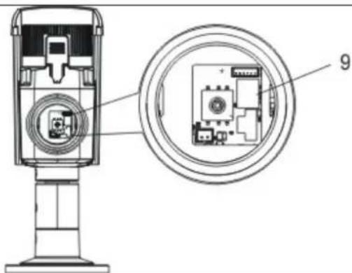
| 9 | HDCC61510: Switch between HD-TVI and analogue video output |
| 10 | Joystick for controlling the on-screen display |
| 11 | Additional connection for analogue video output (2-pin adapter provided in scope of delivery) |
| Focus | Focus setting |
| Zoom | Zoom setting |
5. Mounting/installation
5.1. Mounting the camera

IMPORTANT!
The camera must be disconnected from the power supply during installation.
Use the accompanying drilling template for drilling the mounting holes. An opening is provided on the base plate of the mount for cabling at the side. Use screw anchors and screws that are appropriate to the surface to fix the camera in place.
Cabling can be at the side or hidden in the ceiling or wall.

natural_image
Technical line drawing of a mechanical device with a vertical support structure and mounting bracket (no text or symbols)Orientation of the camera, as described below, can now be performed. At this point, an analogue test monitor may be connected to the camera (for test purposes only, can be activated in place of the HD-TVI signal on 720p models). The monitor is connected either to the connecting cable on the camera or to the underside of the camera using the supplied adapter.

Tighten the fixing screws again after orienting the camera.
5.2. Orientation of the camera
The camera module can be oriented in three axes.

1: Fixing screw (rotation)
2: Fixing screw (tilt)
3: Fixing screw (turn)
Zoom and focus setting is performed after orienting the camera. The corresponding setting options can be found on the underside of the camera.

The IR range is strongly dependent on the environmental conditions. If the area in the camera's field of view reflects poorly or if there are no objects within the max. illumination range, the brightness of the video image at night may be too low. This will result in poor usability of the video image.
In addition, when installing the camera it must be ensured that no objects are located in close proximity to the camera's field of view (e.g. roof gutter or wall). These objects can reflect back the IR light, resulting in circular fading on the video image in the opposite direction to the object.
5.3. Power supply

IMPORTANT!
Before starting installation, ensure that the power supply voltage and the rated voltage of the camera are identical.
The cameras require a 12 V DC or 24 V AC power supply. The polarity of the DC voltage supply does not need to be observed!
5.4. Connecting the video cable
In order to transmit the HD-TVI video signal from the camera to a recorder, an RG59 or RG6 type coaxial cable with BNC connector (male) must be connected to the connection labelled 'TVI'. The cable length to the next device must not exceed 500 m (RG6) or 300 m (RG59).
An RG59 or RG6 type coaxial cable can be connected to the analogue video output (labelled 'CVBS'). The cable length to the next device must not exceed 100 m.

To ensure optimum quality of the HD-TVI signal transmission, it is important that the cable is neither kinked nor crushed at any point, and that its radius is adequate (min. bending radius 6 cm).
Damage to the cable or porosity as a result of ageing can have a negative impact on the quality of the signal or image (e.g. shadowing around the edges).
5.5. Switching between HD-TVI and analogue video output
A switch on the PCB of the camera module allows you to activate either the HD-TVI output or the analogue video output.
This model does not allow both outputs to be activated at the same time.

After installation and orientation of the camera module, move the switch to the 'TVI' position to activate the HD-TVI output.
6. On-screen display
6.1. Opening the on-screen display
This camera's on-screen display can be opened either using the joystick on the underside or via the ABUS HD-TVI DVR. Please consult the user manual for the ABUS HD-TVI DVR.
6.2. Description of the on-screen display
Pressing the on-screen display control button opens the on-screen display. This on-screen display allows you to adjust a number of detailed settings.
| SETUP | |
| VIDEO STANDARD PALLANGUAGE ENGLISHMAIN MENU ↓ |
| Function Description | |
| VIDEO STANDARD Video standard setting | PAL: Video output and service monitor output are set to the 50 Hz standard (e.g. 720p50, 1080p50 or PAL)NTSC: Video output and service monitor output are set to the 60 Hz standard (e.g. 720p60, 1080p60 or NTSC) |
| LANGUAGE Setting for the language of the on-screen display | For this camera model, English is currently the only available language. |
| MAIN MENU Advanced camera settings | Press the ENTER button to open the advanced camera settings menu. |
MAIN MENU
| SETUP | |
| AE | ↓ |
| WB | AUTO |
| DAY&NIGHT | SMART↓ |
| VIDEO SETTING ↓ | |
| FUNCTION | ↓ |
| RESET | |
| SAVE&EXIT | SAVE |
AE
This menu item allows you to adjust general exposure settings, e.g. whether the camera should process high contrasts or whether the camera requires special settings for night vision.
| Function Description | |
| BRIGHTNESS (1~10): Picture brightness setting | |
| AE MODE GLOBAL AE: General automatic exposure setting without DWDR functionDWDR: Automatic exposure setting with DWDR function.The DWDR function enables improved display of high image contrasts. The function brightens dark areas of the video image, whilst maintaining the brightness of light areas. | |
| AGC Automatic gain control. As the setting is increased, the video image appears lighter in poor lighting conditions, although the higher the setting the higher the image noise.OFF: DeactivatedLOW: LowMIDDLE: MediumHIGH: High | |
| SENSE UP (0~16): Continuous exposure setting. Longer exposure times for each image make the resulting image lighter. However, the longer the exposure time, the lower the frame rate.0: deactivated2~16: Exposure time increased by a factor of x | |
| RETURN | Return to previous menu screen |
WB
This menu item allows you to adjust the white balance settings.
| Function Description | |||
| AUTO Automatic white balance | |||
| MANUAL | Manual | white | balance |
| RGAIN: Gain factor for proportion of red in image | |||
| BGAIN: Gain factor for proportion of blue in image | |||
| RETURN: Return to previous menu screen | |||
DAY&NIGHT
This menu item allows you to set the mode for day/night switching.
| Function Description | |
| SMART Automatic activation/deactivation of day mode or night mode. The integrated photo sensor controls the switchover according to the lighting level.INFRARED-LAMP: ON: IR LEDs activated in night modeOFF: IR LEDs deactivated in night modeSMART-IR (0~5): The higher the value, the darker the IR LEDs for very close objects (reduction of IR light intensity).RETURN: Return to previous menu screen | |
| COLOUR The camera stays in colour mode permanently. The infrared cut filter is constantly in front of the lens, and the IR LEDs are constantly off. | |
| B/W The camera stays in black/white mode permanently. The infrared cut filter is constantly separated from the lens. The IR LEDs are switched on and off automatically by the photo sensor. | |
VIDEO SETTING
This menu item allows you to adjust general image settings, such as contrast or video image mirroring.
| Function Description | |
| CONTRAST (1~10): | Image contrast setting |
| SHARPNESS | This function allows image sharpness perception to be adjusted electronically.EDGE (1~10): Change how the edge is displayed in light areasDETAIL (1~10): Change the sharpness setting of the imageRETURN: Return to previous menu screen |
| COLOUR GAIN | (1~10): Saturation of the video image |
| 3DNR | Noise reduction function setting. The higher the value set, the more noise will be removed from the video image by the software.OFF: DeactivatedLOW: LowMIDDLE: MediumHIGH: High |
| MIRROR Mirroring of the video image | OFF: DeactivatedHV: Horizontal and vertical image mirroringV: Vertical image mirroringH: Horizontal image mirroring |
| RETURN Return to previous menu screen | |
FUNCTION
| Function Description | |
| DETECTION | Not usedThe camera's internal motion detection is integrated into the processor platform by default. This camera type does not have an interface (e.g. alarm output) to allow this function to be used. |
| MASKING Privacy masking settings. A maximum of eight private zones may be freely defined in terms of size and position.COLOUR: Setting for the colour of all masksAREA NO. 0~7: Setting for the individual maskSTATUS: ON: Mask activeOFF: Mask deactivatedHORIZON. SIZE: Horizontal size of the maskVERTICAL SIZE: Vertical size of the maskHORIZON. MOVE: Horizontal starting position of the maskVERTICAL MOVE: Vertical | |
| ZOOM IN (50/60/70/80/90/100)Digital zoom function. A value of 100 means than no digital zoom is set. A value of 50 means that 50% of the image, as seen from the centre of the screen, is displayed as the camera image. | |
| RETURN Return to previous menu screen | |
RESET
| Function Description | |
| RESET | Reset all camera settings in the main menu to the factory settings |
SAVE&EXIT
| Function | Description |
| SAVE | Save all settings and exit the on-screen display |
| EXIT | Exit the on-screen display |
7. Maintenance and cleaning
7.1. Maintenance
Regularly check the technical safety of the product, e.g. check the housing for damage.
If it appears to no longer be possible to operate the device safely, stop using the product and secure it to prevent unintentional use.
It is likely that safe operation is no longer possible in the event that:
- the device shows signs of visible damage
- the device no longer works correctly.

Please note:
You do not need to perform any maintenance on the product. There are no components to service and nothing inside the product to check. Never open it.
7.2. Cleaning
Clean the product with a clean, dry cloth. The cloth can be dampened with lukewarm water to remove stubborn dirt.

Do not allow any liquids to enter the device.
Do not use any chemical cleaning products as they could damage the surface of the housing and screen (discolouration).
8. Disposal

Important: EU Directive 2002/96/EC regulates the proper return, treatment and recycling of used electronic devices. This symbol means that in the interest of environmental protection, the device must be disposed of separately from household or industrial waste at the end of its service life in accordance with applicable local legal guidelines. Used devices can be disposed of at official recycling centres in your country. Obey local regulations when disposing of material. Further details on returns (also for non-European countries) can be obtained from your local authority. Separate collection and recycling conserves natural resources and ensures that all the provisions for protecting health and the environment are observed when recycling the product.
9. Technical data
| Model number HDCC61510 | |
| Image sensor 1/3 inch progressive scan CMOS | |
| Camera type Vario tube | |
| Resolution | 720p25, |
| Pixels (effective) 1920 (H) x 1080 (V) | |
| Lens 2.8–12 mm, varifocal lens | |
| Horizontal angle of view 32°–78° | |
| Day/night switching Electromechanical IR cut filter | |
| Minimum illumination (colour) 0.1 Lux | |
| Minimum illumination (B/W) 0.001 Lux (image integration on) | |
| Minimum illumination (IR) 0 Lux | |
| Image integration 2x–16x | |
| Noise reduction 3D DNR | |
| Electronic shutter control | 1/50 s to 1/50,000 s |
| Camera control On-screen display (OSD) | |
| Backlight compensation | DWDR |
| Privacy masking | Eight freely configurable areas |
| Digital zoom | Yes |
| Video system | HD-TVI |
| IR LEDs | 42 |
| IR range | 40 m |
| Smart IR | Yes |
| Connections | Video signal (HD-TVI, BNC), video signal (FBAS, BNC), power supply |
| Power supply | 12 V DC ± 10%, 24 V AC ± 10% |
| Power consumption | Max. mA (max. W) |
| Operating temperature | -20°C–+60°C |
| Humidity | Max. 90% |
| Dimensions (L x W x H) | 267 x 92 x 115 mm |
| Weight | 900 g |

The IR range is strongly dependent on the environmental conditions. If the area in the camera's field of view reflects poorly or if there are no objects within the max. illumination range, the brightness of the video image at night may be too low. This will result in poor usability of the video image.
In addition, when installing the camera it must be ensured that no objects are located in close proximity to the camera's field of view (e.g. roof gutter or wall). These objects can reflect back the IR light, resulting in circular fading on the video image in the opposite direction to the object.
HDCC61510
natural_image
Technical line drawing of a mechanical assembly or enclosure (no text or symbols)natural_image
Technical line drawing of a mechanical device with a vertical support and mounting bracket (no text or symbols)natural_image
Technical line drawing of a mechanical assembly or enclosure (no text or symbols)natural_image
Technical line drawing of a mechanical device with a vertical support structure and mounting bracket (no text or symbols)6. Schermmenu
6.1. Schermmenu (OSD) openen
natural_image
Technical line drawing of a mechanical assembly or enclosure (no text or symbols)natural_image
Technical line drawing of a mechanical device with a vertical support and mounting bracket (no text or symbols)6. Skæmmenu
natural_image
Technical line drawing of a mechanical assembly or enclosure (no text or symbols)Instrukcja obsługi
Wersja 10/2015
CE
natural_image
Technical line drawing of a mechanical device with a vertical support structure (no text or symbols)6. Menu ekranowe
natural_image
Technical line drawing of a mechanical assembly or enclosure (no text or symbols)natural_image
Technical line drawing of a mechanical device with a vertical support structure (no text or symbols)6. Меню экрана
These operating instructions are published by ABUS Security-Center GmbH & Co.KG, Linker Kreuthweg 5, 86444 Affing, Germany. No reproduction (including translation) is permitted in whole or part e.g. photocopy, microfilming or storage in electronic data processing equipment, without the express written consent of the publisher.
The operating instructions reflect the current technical specifications at the time of print.
We reserve the right to change the technical or physical specifications.
© Copyright Ⅲ/2015 by ABUS Security-Center
- HDCC61510
- Bedienungsanleitung
- Bildschirmmenü
- User manual
- Introduction
- Disclaimer
- Explanation of symbols
- Important safety information
- The following safety information and hazard notes are not only intended to protect your health, but also to protect the device from damage. Please read the following points carefully:
- Safety information
- Warnings
- Unpacking the device
- Contents
- Intended use
- Scope of delivery
- Features and functions
- Camera description
- Mounting/installation
- Mounting the camera
- IMPORTANT!
- Orientation of the camera
- Power supply
- Connecting the video cable
- Switching between HD-TVI and analogue video output
- On-screen display
- Opening the on-screen display
- Description of the on-screen display
- MAIN MENU
- AE
- WB
- DAY&NIGHT
- VIDEO SETTING
- Maintenance and cleaning
- Maintenance
- Please note:
- Cleaning
- Disposal
- Technical data
- Schermmenu
- Schermmenu (OSD) openen
- Skæmmenu
- Instrukcja obsługi
- Menu ekranowe
- Меню экрана
Brand : ABUS
Model : HDCC61510
Category : Surveillance Camera