
P7214 - Server AXIS - Free user manual and instructions
Find the device manual for free P7214 AXIS in PDF.


| Product type | Video server / network encoder |
| Brand | AXIS |
| Model | P7214 |
| Dimensions (L x W x H) | Approx. 430 x 250 x 44 mm (1U rack mount) |
| Weight | Approx. 3.5 kg |
| Power supply | 100-240 V AC, 50-60 Hz, max consumption 30 W |
| Max video resolution | H.264, H.265, up to 1920x1080 at 30 fps |
| Video inputs | 4 BNC inputs (analog) or 4 IP inputs via network |
| Video output | 1 HDMI output (local monitor) |
| Network connectivity | 1 Ethernet port 10/100/1000 Base-T |
| Internal storage | Slot for 2.5-inch SATA hard drive (not included) |
| Main functions | Video encoder, streaming server, NAS recording, motion detection, remote management via web interface |
| Maintenance and cleaning | Regularly dust ventilation grilles with a soft, dry cloth. Do not use chemicals. |
| Security | Password protection, HTTPS encryption, IP filtering, digital certificates |
| Spare parts and repairability | Replaceable hard drive, standard fan. Other parts require an Axis certified technician. |
| General information | Operating temperature: 0 to 45 °C. Humidity: 10-85% non-condensing. 2-year warranty. |
Frequently Asked Questions - P7214 AXIS
User questions about P7214 AXIS
0 question about this device. Answer the ones you know or ask your own.
Ask a new question about this device
Download the instructions for your Server in PDF format for free! Find your manual P7214 - AXIS and take your electronic device back in hand. On this page are published all the documents necessary for the use of your device. P7214 by AXIS.
USER MANUAL P7214 AXIS
This document includes instructions for installing the AXIS P7214/P7210 on your network. Previous experience of networking will be beneficial when installing the product.
Legal Considerations
Video and audio surveillance can be prohibited by laws that vary from country to country. Check the laws in your local region before using this product for surveillance purposes.
This product includes one (1) H.264 decoder license and one (1) AAC license. To purchase further licenses, contact your reseller.
Electromagnetic Compatibility (EMC)
This equipment generates, uses and can radiate radio frequency energy and, if not installed and used in accordance with the instructions, may cause harmful interference to radio communications. However, there is no guarantee that interference will not occur in a particular installation.
If this equipment does cause harmful interference to radio or television reception, which can be determined by turning the equipment off and on, the user is encouraged to try to correct the interference by one or more of the following measures: Re-orient or relocate the receiving antenna. Increase the separation between the equipment and receiver. Connect the equipment to an outlet on a different circuit to the receiver. Consult your dealer or an experienced radio/TV technician for help. Shielded (STP) network cables must be used with this unit to ensure compliance with EMC standards.
USA – This equipment has been tested and found to comply with the limits for a Class B computing device pursuant to Subpart B of Part 15 of FCC rules, which are designed to provide reasonable protection against such interference when operated in a commercial environment. Operation of this equipment in a residential area is likely to cause interference, in which case the user at his/her own expense will be required to take whatever measures may be required to correct the interference.
Canada - This Class B digital apparatus complies with Canadian ICES-003.
Europe - C€ This digital equipment fulfills the requirements for radiated emission according to limit B of EN55022, and the requirements for immunity according to EN55024 residential and commercial industry.
Japan - This is a class B product based on the standard of the Voluntary Control Council for Interference from Information Technology Equipment (VCCI). If this is used near a radio or television receiver in a domestic environment, it may cause radio interference. Install and use the equipment according to the instruction manual.
Australia – This electronic device meets the requirements of the Radio communications (Electromagnetic Compatibility) Standard AS/NZS CISPR22.
This product is intended to receive power from an external power supply. This supply shall meet the requirements for Safety Extra Low Voltage and Limited Power Source according to EN 60 950-1.
Equipment Modifications
This equipment must be installed and used in strict accordance with the instructions given in the user documentation. This equipment contains no user-serviceable components. Unauthorized equipment changes or modifications will invalidate all applicable regulatory certifications and approvals.
Liability
Every care has been taken in the preparation of this document. Please inform your local Axis office of any inaccuracies or omissions. Axis Communications AB cannot be held responsible for any technical or typographical errors and reserves the right to make changes to the product and documentation without prior notice. Axis Communications AB makes no warranty of any kind with regard to the material contained within this document, including, but not limited to, the implied warranties of merchantability and fitness for a particular purpose. Axis Communications AB shall not be liable nor responsible for incidental or consequential damages in connection with the furnishing, performance or use of this material.
RoHS
This product complies with both the European RoHS directive, 2002/95/EC, and the Chinese RoHS regulations, ACPEIP.

WEEE Directive
The European Union has enacted a Directive 2002/96/EC on Waste Electrical and Electronic Equipment (WEEE Directive). This directive is applicable in the European Union member states.

The WEEE marking on this product (see right) or its documentation indicates that the product must not be disposed of together with household waste. To prevent possible harm to human health and/or the environment, the product must be disposed of in an approved and environmentally safe recycling process. For further information on how to dispose of this product correctly, contact the product supplier, or the local authority responsible for waste disposal in your area. Business users should contact the product supplier for information on how to dispose of this product correctly. This product should not be mixed with other commercial waste. For more information, visit www.axis.com/techsup/commercial waste.
Support
Should you require any technical assistance, please contact your Axis reseller. If your questions cannot be answered immediately, your reseller will forward your queries through the appropriate channels to ensure a rapid response. If you are connected to the Internet, you can:
- download user documentation and firmware updates
- find answers to resolved problems in the FAQ database. Search by product, category, or phrases
- report problems to Axis support by logging in to your private support area.
The AXIS P7214/P7210 uses a 3.0V CR2032 Lithium battery, for more information please see page 3.
Safeguards
Please read through this Installation Guide carefully before installing the product. Keep the Installation Guide for further reference.

CAUTION!
- When transporting the Axis product, use the original packaging or equivalent to prevent damage to the product.
- Store the Axis product in a dry and ventilated environment.
- Avoid exposing the Axis product to vibration, shocks or heavy pressure and do not install the camera on unstable brackets, unstable or vibrating surfaces or walls, since this could cause damage to the product.
- Only use handtools when installing the Axis product, the use of electrical tools or excessive force could cause damage to the product.
- Do not use chemicals, caustic agents, or aerosol cleaners. Use a damp cloth for cleaning.
- Use only accessories that comply with technical specification of the product. These can be provided by Axis or a third party.
- Use only spare parts provided by or recommended by Axis.
- Do not attempt to repair the product by yourself, contact Axis or your Axis reseller for service matters.

IMPORTANT!
- This Axis product must be used in compliance with local laws and regulations.
Battery replacement
This Axis product uses a 3.0V CR2032 Lithium battery as the power supply for its internal real-time clock (RTC). Under normal conditions this battery will last for a minimum of 5 years. Low battery power affects the operation of the RTC, causing it to reset at every power-up. A log message will appear when the battery needs replacing. The battery should not be replaced unless required!
If the battery does need replacing, please contact www.axis.com/techsup for assistance.
- Danger of Explosion if battery is incorrectly replaced.
- Replace only with the same or equivalent battery, as recommended by the manufacturer.
- Dispose of used batteries according to the manufacturer's instructions.
AXIS P7214/P7210 Video Encoder Installation Guide
This installation guide provides instructions for installing a AXIS P7214/P7210 video encoder on your network. For all other aspects of using the product, please see the product's User's Manual, available on the CD included in this package, or from www.axis.com
Installation steps
Follow these steps to install the AXIS P7214/P7210 on your local network (LAN):
- Check the package contents against the list below.
- Hardware overview. See page 6.
- Install the hardware. See page 7.
- Assign an IP address. See page 9.
- Set the password. See page 12.
Important!
This product must be used in compliance with local laws and regulations.
1 Package contents
| Item Models/variants/notes | |
| Axis video encoder models AXIS P7214AXIS P7210 | |
| Power adapter models AXIS P7214: Type PS-KAXIS P7210: Type PS-P | |
| Mounting kit AXIS P7214 | 4 screws and 4 plugs to mount the encoder to a concrete wallAXIS P72108 screws (for mounting with brackets)4 M6x20 screws for mounting in rack2 mounting bracketsAXIS P7214/P72104 Surface protection padsTerminal block connectors (I/O: 6-pin connector, RS-485/RS-422: 2 x 2-pin connector for AXIS P7214; 8 x 2 pin connector for AXIS P7210, Power: 2-pin connector) |
| CD AXIS Network Video Product | CD, including product documentation,installation tools and other software |
| Printed Materials AXIS P7214/P7210 Installation Guide (this document)Axis Warranty Document | |

Hardware overview
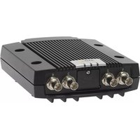
AXIS P7214
Front view Rear view

Front view

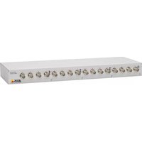
AXIS P7210 - rear view

Audio output 1

Dimensions
| AXIS P7214 | HxWxD = 37x109x172Weight = 570g (1.26 lbs) |
| AXIS P7210 | HxWxD = 45x440x165Weight = 2540g (5.6 lbs) |
3 Install the hardware
Important!
The casing of the AXIS P7214/P7210 is not approved for outdoor use – the product may only be installed in indoor environments.
Notes:
- The AXIS P7214/P7210 can simply be placed on a flat surface or mounted. See below for mounting instructions.
- Punch out the protective pads and stick them to the underside of the video encoder to prevent scratches on the surface where the video encoder is placed.
Mount the video encoder (AXIS P7214)
The video encoder is supplied with a mounting kit containing screws and plugs for mounting the video encoder on a concrete wall:
- Place the video encoder against the wall, and mark the four mounting holes (see image on page 6).
- Drill the four mounting holes.
- Insert the provided wall plugs into the wall, and attach it to the wall using the screws provided.
Mount the video encoder (AXIS P7210)
The video encoder is supplied with a mounting kit containing brackets and screws. The unit can be mounted in a rack or on a wall:
After removing the existing 4 screws, attach the mounting bracket to the video encoder at an angle suitable for installation in a standard 1U 19" rack, or on the wall.
AXIS P7210 on wall AXIS P7210 on


natural_image
Pure electrical circuit lines without any symbolsMounting bracket
Bracket position for rack mount

Bracket position for wall mount
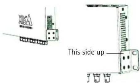
Note: Each bracket must be attached to the appropriate side of the video encoder, and at an appropriate angle depending on whether it is mounted on the wall or in the rack.
Mounting on wall
- Position the video encoder against the wall with the brackets attached, and mark the four mounting holes for each bracket (see image above).
- Drill the four mounting holes.
- Attach the video encoder to the wall using appropriate screws.
Connect the cables
- Connect the encoder to the network using shielded network cables. If using PoE see note below.
- Optionally connect external input/output devices, e.g. alarm devices. See page 15 for information on the terminal connector pins.
- Optionally connect active speakers and/or external microphones.
- Connect the cameras to the video inputs.
- If powering the unit with DC input, connect the supplied indoor power adapter or an external power supply. See note below.
- Check that the indicator LEDs indicate the correct conditions. See the table on page 17 for further details.
Note: The unit can be powered using either the DC power input or PoE.
If powering the unit using DC power, connect the power supply to the power connector at the rear of the unit.
If powering the unit using PoE, connect a PoE network cable. For AXIS P7210, connect 4 PoE network cables (one for each group).

Assign an IP address
Most networks today have a DHCP server that automatically assigns IP addresses to connected devices. If your network does not have a DHCP server the AXIS P7214 will use 192.168.0.90 as the default IP address.
AXIS P7210 will use 4 different IP addresses for each group of 4 video input connectors. Numbers on the video encoder indicate each set of 4. 192.168.0.90 is the default IP address for group 1, 192.168.0.91 for group 2, 192.168.0.92 for group 3, and 192.168.0.93 for group 4.
AXIS IP Utility and AXIS Camera Management are recommended methods for setting an IP address in Windows. These free applications are available on the Axis Network Video Product CD supplied with this product, or they can be downloaded from www.axis.com/techsup. Depending on the number of cameras you wish to install, use the method that suits you best.
| Method Recommended for Operating system | |||
 | AXIS IP UtilitySee page 10 | Single video encoderSmall installations | Windows |
 | AXIS Camera ManagementSee page 11 | Multiple video encodersLarge installationsInstallation on a different subnet | Windows 2000Windows XP ProWindows 2003 ServerWindows Vista |
Notes:
- If assigning the IP address fails, check that there is no firewall blocking the operation.
- For other methods of assigning or discovering the IP address of the AXIS P7214/P7210, e.g. in other operating systems, see page 14.
AXIS IP Utility - single camera/small installation
AXIS IP Utility automatically discovers and displays Axis devices on your network. The application can also be used to manually assign a static IP address.

Note that the computer running AXIS IP Utility must be on the same network segment (physical subnet) as the AXIS P7214/P7210.
Automatic discovery
- Check that the AXIS P7214/P7210 is connected to the network and that power has been applied.
- Start AXIS IP Utility.
- When the AXIS P7214/P7210 appears in the window, double-click it to open its home page. AXIS P7210 appears in the window with one entry for each of its 4 groups of video inputs.
- See page 12 for instructions on how to assign the password.
Set the IP address manually (optional)
- Acquire an unused IP address on the same network segment as your computer.
- Select AXIS P7214 or one of the AXIS P7210 in the list.
- Click the button IP Assign new IP address to selected device and enter the IP address.
- Click the Assign button and follow the instructions.
- Click the Home Page button to access the video encoder's web pages.
- See page 12 for instructions on how to set the password.
AXIS Camera Management - multiple cameras/large installations
AXIS Camera Management can automatically find and set IP addresses, show connection status, and manage firmware upgrades for multiple Axis video products.
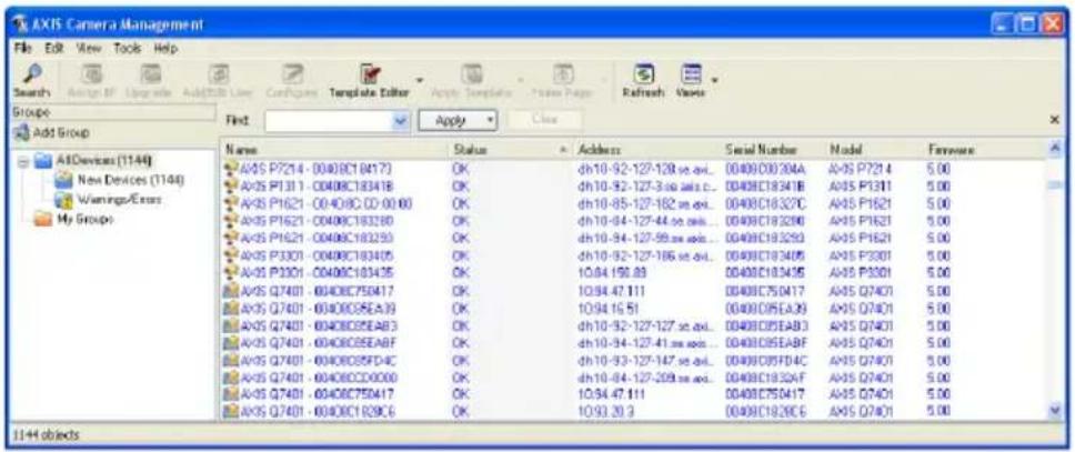
Automatic discovery
- Check that the encoder is connected to the network and that power has been applied.
- Start AXIS Camera Management. When the video encoder appears in the window, double-click it to open the encoder's home page.
AXIS P7210 appears in the window with one entry for each of its four groups of video input connectors.
- See page 12 for instructions on how to set the password.
Assign an IP address in a single device
- Select the video encoder in AXIS Camera Management and click the Assign IP button.
- Select Assign the following IP address and enter the IP address, the subnet mask and default router the device will use.
- Click the OK button.
Assign IP addresses in multiple devices
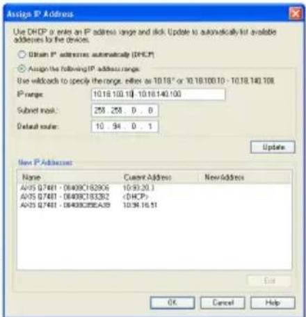
AXIS Camera Management speeds up the process of assigning IP addresses to multiple devices, by suggesting IP addresses from a specified range.
- Select the devices you wish to configure (different models can be selected) and click the Assign IP button.
- Select Assign the following IP address range and enter the range of IP addresses, the subnet mask and default router the devices will use.
- Click the OK button.


5 Set the password
To gain access to the product, the password for the default administrator user root must be set. This is done in the 'Configure Root Password' dialog, which is displayed when the AXIS P7214/P7210 is accessed for the first time.
To prevent network eavesdropping when setting the root password, this can be done via an encrypted HTTPS connection, which requires an HTTPS certificate (see note below).
To set the password via a standard HTTP connection, enter it directly in the first dialog shown below.
To set the password via an encrypted HTTPS connection, follow these steps:
- Click the Create self-signed certificate button.
- Provide the requested information and click OK. The certificate is created and the password can now be set securely. All traffic to and from the AXIS P7214/P7210 is encrypted from this point on.
- Enter a password and then re-enter it to confirm the spelling. Click OK. The password has now been configured.
![To create an HTTPS connection, start by clicking this button. Create Certificate Secure configuration of the root password via HTTPS requires a self-signed certificate. Create self-signed certificate... Configure Root Password User name: root Password: Confirm password: The password for the pre-configured administrator before the product can be used. If the password for root is lost, the product must be reset to the factory default settings, by pressing the button located in the product's casing. Please see the user documentation for more information. Create Self-Signed Certificate Common name: 10.92.127.20 Validity: 365 days [1..9999] *The name of the entity to be certified, i.e. the IP address or host name of this product. OK Cancel Once the certificate is created, this p configure the root password via HTTP Configure Root Password using HTTP User name: root Password: Confirm password: OK The password for the pre-configured administrator root must be changed before the product can be used. If the password for root is lost, the product must be reset to the factory default settings, by pressing the button located in the product's casing. Please see the user documentation for more information.](/content/2026/06/1263700/images/204a909fe12c7541b3f99b144a8c4a654cf19c1a39571a2f9f4c090de6ffc528.jpg)
- To log in, enter the user name "root" in the dialog as requested.
Note: The default administrator user name root cannot be deleted.
- Enter the password as set above, and click OK. If the password is lost, the AXIS P7214/P7210 must be reset to the factory default settings. See page 18.
-
If required, click Yes to install AMC (AXIS Media Control), which allows viewing of the video stream in Internet Explorer. You will need administrator rights on the computer to do this.
-
The Live View page of the AXIS P7214/P7210 is displayed. The Setup link leads to menus which allow you to customize the encoder.
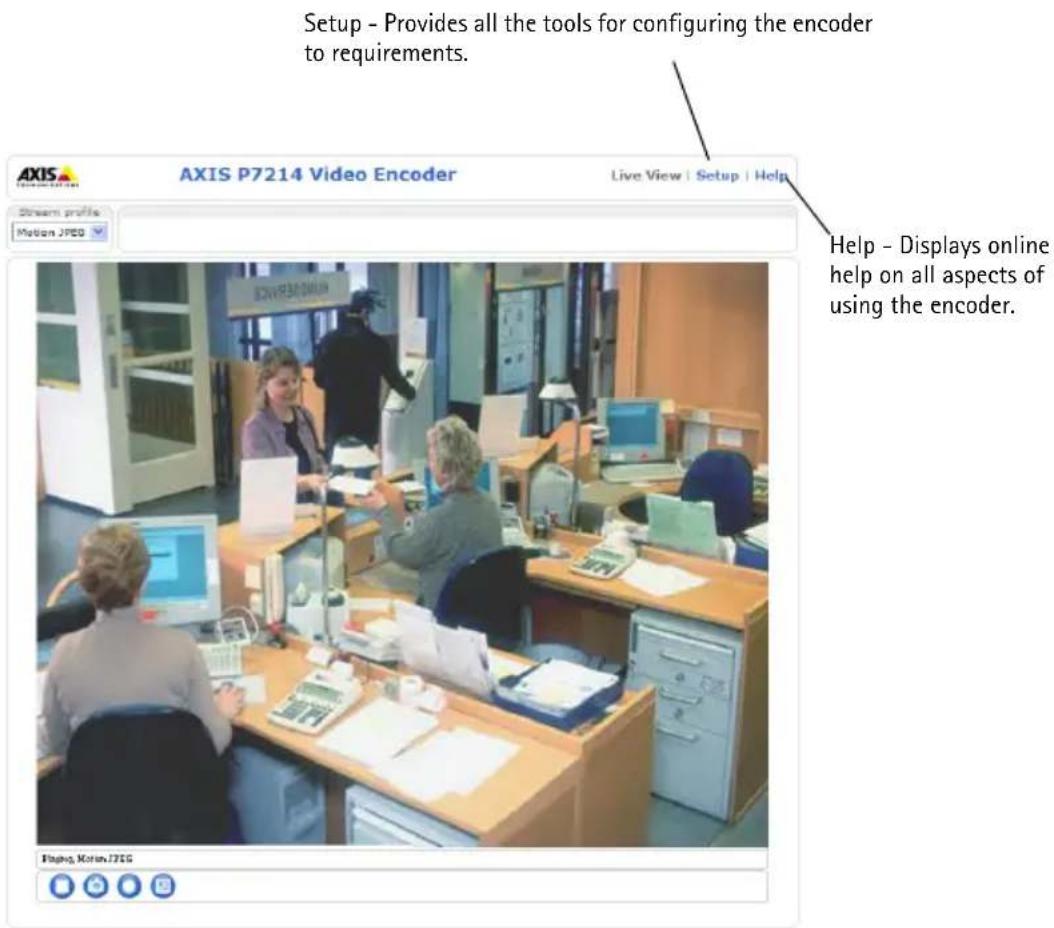
Notes:
- HTTPS (Hypertext Transfer Protocol over SSL) is a protocol used to encrypt the traffic between web browsers and servers. The HTTPS certificate controls the encrypted exchange of information.
- The default administrator user root cannot be deleted.
- If the password for root is lost or forgotten, the AXIS P7214/P7210 must be reset to the factory default settings. See page 18.
Other methods of setting the IP address
The table below shows other methods available for setting or discovering the IP address. All methods are enabled by default, and all can be disabled.
| Use in operating system | Notes | |
| UPnPTM | Windows When enabled on your computer, the video encoder is automatically detected and added to "My Network Places." | |
| Bonjour | MAC OSX (10.4 or later) | Applicable to browsers with support for Bonjour. Navigate to the Bonjour bookmark in your browser (e.g. Safari) and click on the link to access the video encoder's web pages. |
| AXIS Dynamic DNS Service | All A free service from Axis that allows you to quickly and simply install your video encoder. Requires an Internet connection with no HTTP proxy. See www.axiscam.net for more information. | |
| ARP/Ping | All See below. The command must be issued within 2 minutes of connecting power to the video encoder. | |
| View DHCP server admin pages | All To view the admin pages for the network DHCP server, see the server's own documentation. | |
Set the IP address with ARP/Ping
- Acquire a free static IP address on the same network segment your computer is connected to.
- Locate the serial number (S/N) or numbers on the AXIS P7214/P7210 label.
- Open a command prompt on your computer and enter the following commands:
| Windows syntax Windows example | |
| arp -s <IP Address> <Serial Number> ping -l 408 -t <IP Address> | arp -s 192.168.0.125 00-40-8c-18-10-00 ping -l 408 -t 192.168.0.125 |
| UNIX/Linux/Mac syntax UNIX/Linux/Mac example | |
| arp -s <IP Address> <Serial Number> temp ping -s 408 <IP Address> | arp -s 192.168.0.125 00:40:8c:18:10:00 temp ping -s 408 192.168.0.125 |
- Check that the network cable is connected to the AXIS P7214/P7210 and then start/restart the AXIS P7214/P7210, by disconnecting and reconnecting power. If PoE is used, start/restart the AXIS P7214/P7210 by disconnecting and then reconnecting the network cable.
- Close the command prompt when you see 'Reply from 192.168.0.125:...' or similar.
- In your browser, type in http://
in the Location/Address field and press Enter on your keyboard.
Notes:
- To open a command prompt in Windows: from the Start menu, select Run... and type cmd. Click OK.
- To use the ARP command on a Mac OS X, use the Terminal utility in Application > Utilities.
Unit connectors
Network connector - RJ-45 Ethernet connector. Supports Power over Ethernet (PoE) Class 3 - max 12.95W. Using shielded cables is recommended.
Power input connector - 2-pin terminal block used for power input from the supplied power adapter or an external power supply.
The external power supply alternatives are:

- The Axis delivered PS-K P/N 34987 (AXIS P7214).
- The Axis delivered PS-P P/N 42118 (AXIS P7210).
- An external 8-20 V DC limited power source with a maximum output current of 5A.
| Function | Pin number | Description |
| GND 1 Ground | ||
| DC Power 2 Power input 8-20V DCmax 8W (AXIS P7214)max 32W (AXIS P7210) | ||
Audio in/out - Two 3.5 mm jacks for audio input, and one 3.5 mm jack for audio output. Stereo plugs must be used.
- Audio Input 1, 2: Microphone or line level inputs (mono). A selectable 2.0V, 2.5V or 3.0V microphone bias is available.
- Audio Output 1: Line level audio output (mono), that can be connected to a public address (PA) system or an active speaker with a built-in amplifier.

| Audio Input 1, Audio Input 2 Audio Output 1 | ||
| 1 Tip Microphone/Line in Line out (mono) | ||
| 2 Ring | ||
| 3 Sleeve GND GND | ||
I/O terminal connector - Used in applications for e.g. motion detection, event triggering, time lapse recording and alarm notifications. In addition to an auxiliary power and a GND pin, the AXIS P7214/P7210 has 4 pins that can be configured as either input or output. These pins provide the interface to:

- Transistor output – For connecting external devices such as relays and LEDs. Connected devices can be activated by AXIS VAPIX API, output buttons on the Live View page or by an Event Type. The output will show as active (shown under Event Configuration > Port Status) if the alarm device is activated.
- Digital input – An alarm input for connecting devices that can toggle between an open and closed circuit, for example: PIRs, door/window contacts, and glass break detectors. When a signal is received the state changes and the input becomes active (shown under Event Configuration > Port Status.).
| Function | Pin | Notes Specifications | |
| GND 1 Ground | |||
| 3.3 VDC Power output | 2 Can be | used to power auxiliary equipment. Max load = 250 mA | |
| Configurable (Input or Output) | 3 - 6 Digital input - Connect to GND to activate, or leave floating (or unconnected) to deactivate. | 0 to +40V DC | |
| Digital output - Internal connection to ground when activated, floating (unconnected) when deactivated. If used with an external relay, a diode must be connected in parallel with the load, for protection against voltage transients. | |||
RS-485/RS-422 connector - Two 2-pin terminal blocks for RS-485/RS-422 serial interface used to control auxiliary equipment, e.g. PTZ devices.
The RS-485/RS-422 serial port can be configured to support:
- Two-wire RS-485 half duplex
- Four-wire RS-485 full duplex
- Two-wire RS-422 simplex
- Four-wire RS-422 full duplex point to point communication

| Function Pin Notes | ||
| RS-485/RS-422 RX/TX A 1 (RX) For full duplex RS-485/RS-422(RX/TX) For half duplex RS-485 | ||
| RS-485/RS-422 RX/TX B 2 | ||
| RS-485/RS-422 TX A 3 (TX) For full duplex RS-485/RS-422 | ||
| RS-485/RS-422 TX B 4 | ||
microSD memory card slot - The microSD memory card can be used for local recording with removable storage.
BNC connector - Connect a 75 ohm coaxial video cable (max. length 800 feet (250 meters)).
Note: For each video input 75 Ohm video termination can be enabled/disabled via the product's web page at Video & Audio > Video Input > Video termination. These terminations are enabled on factory default. In cases where the product is to be connected in parallel with other equipment, for optimum video quality, it is recommended that termination be enabled for only the last device in the video signal chain.
LED indicators
| LED Color | Indication | |
| Network | Green | Steady for connection to a 100 Mbit/s network. Flashes for network activity. |
| Amber | Steady for connection to 10 Mbit/s network. Flashes for network activity. | |
| Unlit No network connection. | ||
| Status Green | Steady green for normal operation. | |
| Amber Steady during startup, during reset to factory default or when restoring settings. | ||
| Red | Slow flash for failed upgrade. | |
| Power | Green Normal operation. | |
| Amber Flashes green/amber during firmware upgrade. | ||
Resetting to the factory default settings
This will reset all parameters, including the IP address, to the Factory Default settings:
- Disconnect the power from the AXIS P7214/P7210, or if PoE is used disconnect the network cable.
- Press and hold the Control button and reconnect power or the network cable if PoE is used.
- Keep the Control button pressed until the Status indicator displays amber (this may take up to 15 seconds).
- Release the Control button. When the Status indicator displays green (which can take up to 1 minute) the process is complete and the video encoder has been reset.
- Re-assign the IP address, using one of the methods described in this document.
It is also possible to reset parameters to the original factory default settings via the web interface. For more information, please see the online help or the user's manual.
Accessing the AXIS P7214/P7210 from the Internet
Once installed, your AXIS P7214/P7210 is accessible on your local network (LAN). To access the video encoder from the Internet, network routers must be configured to allow incoming traffic, which is usually done on a specific port.
- HTTP port (default port 80) for viewing and configuration
• RTSP port (default port 554) for viewing H.264 video streams
Please refer to the documentation for your router for further instructions. For more information on this and other topics, visit the Axis Support Web at www.axis.com/techsup
Further information
The user's manual is available from the Axis Web site at www.axis.com or from the Axis Network Video Product CD supplied with this product.
Tip! Visit www.axis.com/techsup to check if there is updated firmware available for your AXIS P7214/P7210. To see the currently installed firmware version, see the About web page.
Mesures de sécurité
| AXIS P7214 | H x L x P = 37 x 109 x 172Poids = 570g |
| AXIS P7210 | H x L x P = 45 x 440 x 165Poids = 2540 g |
natural_image
Front view of a rectangular electronic device with multiple ports and connectors (no visible text or symbols)Montagehalterung
| AXIS P7214 | Alt. x Anch. x Prof. = 37 x 109 x 172Peso = 570 g |
| AXIS P7210 | Alt. x Anch. x Prof. = 45 x 440 x 165Peso = 2540 g |
③ Instale el hardware
Importante:
©2011 Axis Communications AB
Ver. 2.0
Printed: October 2011
Part No. 44132


- Legal Considerations
- Electromagnetic Compatibility (EMC)
- Equipment Modifications
- Liability
- RoHS
- WEEE Directive
- Support
- Safeguards
- CAUTION!
- IMPORTANT!
- Battery replacement
- AXIS P7214/P7210 Video Encoder Installation Guide
- Installation steps
- Hardware overview
- Install the hardware
- Notes:
- Mount the video encoder (AXIS P7214)
- Mount the video encoder (AXIS P7210)
- Mounting on wall
- Connect the cables
- Assign an IP address
- AXIS IP Utility - single camera/small installation
- Automatic discovery
- Set the IP address manually (optional)
- AXIS Camera Management - multiple cameras/large installations
- Assign an IP address in a single device
- Assign IP addresses in multiple devices
- Set the password
- Other methods of setting the IP address
- Set the IP address with ARP/Ping
- Unit connectors
- Resetting to the factory default settings
- Accessing the AXIS P7214/P7210 from the Internet
- Further information
- Mesures de sécurité
- ③ Instale el hardware
- Importante:
Brand : AXIS
Model : P7214
Category : Server