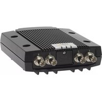
Q7424-R - Server AXIS - Free user manual and instructions
Find the device manual for free Q7424-R AXIS in PDF.


| Product Type | Network Video Server |
| Model | Q7424-R |
| Brand | Axis Communications |
| Video Input | Up to 4 analog cameras via BNC connectors |
| Video Compression | H.264, MPEG-4, MJPEG |
| Resolution Support | Up to D1 (720x480) at 30 fps per channel |
| Audio Support | Two-way audio via terminal blocks |
| Network Interface | 1x 10/100/1000 Mbps Ethernet (RJ-45) |
| Storage | Support for microSD/microSDHC card (not included) |
| Dimensions (W x D x H) | 200 x 140 x 45 mm (7.9 x 5.5 x 1.8 in) |
| Weight | 0.5 kg (1.1 lb) |
| Power Requirements | 12V DC or PoE (Power over Ethernet, IEEE 802.3af/802.3at Type 1) |
| Power Consumption | 12W typical |
| Operating Temperature | 0°C to 45°C (32°F to 113°F) |
| Humidity | Up to 85% RH non-condensing |
| Mounting | Desktop or wall mountable (bracket included) |
| Included Accessories | Quick start guide, installation guide, power adapter |
| Maintenance | Keep vents clean; use dry cloth for cleaning |
| Security | HTTPS encryption, IP address filtering, password protection |
| Firmware | Upgradable via web interface |
| Warranty | 3 years limited |
Frequently Asked Questions - Q7424-R AXIS
User questions about Q7424-R AXIS
0 question about this device. Answer the ones you know or ask your own.
Ask a new question about this device
Download the instructions for your Server in PDF format for free! Find your manual Q7424-R - AXIS and take your electronic device back in hand. On this page are published all the documents necessary for the use of your device. Q7424-R by AXIS.
USER MANUAL Q7424-R AXIS
ThismanualisintendedforadministratorsandusersoftheAXIS Q7424-R Video Encoder, and is applicable to firmware 5.40 and later. Itincludesinstructionsforusingandmanagingtheproductonyour network.Previousexperienceofnetworkingwillbeofusewhenusing thisproduct.SomeknowledgeofUNIXorLinux-basedsystemsmayalso be beneficial, for developing shell scripts and applications. Later version ofthisdocumentwillbepostedtotheAxiswebsite,asrequired.See alsotheproduct'sonlinehelp,availableviatheweb-basedinterface.
Liability
Everycarehasbeentakeninthepreparationofthismanual.Please inform your local Axis office of any inaccuracies or omissions. Axis CommunicationsABcannotbeheldresponsibleforanytechnicalor typographicalerrorsandreservestherighttomakechangestothe productandmanualswithoutpriornoticeAxisCommunicationsAB makesnowarrantyofanykindwithregardtothematerialcontained withinthisdocument,including,butnotlimitedto,theimplied warranties of merchantability and fitness for a particular purpose. Axis CommunicationsABshallnotbeliablenorresponsibleforincidentalor consequentialdamagesinconnectionwiththefurnishing,performance or use of this material. This product is only to be used for its intended purpose.
IntellectualPropertyRights
Axis AB has intellectual property rights relating to technology embodied in the product described in this document. In particular, and without limitation, these intellectual property rights may include one or more of the patents listed at http://www.axis.com/patent.htmandoneor more additional patents or pending patent applications in the US and other countries.
Thisproductcontainslicensedthird-partysoftware.Seethemenuitem "About"intheproduct'suserinterfaceformoreinformation.
ThisproductcontainssourcecodecopyrightAppleComputer, Inc., under the terms of Apple Public Source Lice http://www.opensource.apple.com/apsl).Thesourcecodeisavailable from http://developer.apple.com/darwin/projects/bonjour/
EquipmentModifications
This equipment must be installed and used in strict accordance with the instructions given in the user documentation. This equipment contains no user-serviceable components. Unauthorized equipment changes or modifications will invalidate all applicable regulatory certifications and approvals.
TrademarkAcknowledgments
Apple,Boa,Bonjour,Ethernet,InternetExplorer,Linux,Microsoft,Mozilla,Real,SMPTE,QuickTime,UNIX,Windows,WindowsVistaandWWWareregisteredtrademarksoftherespectiveholders.JavaandallJava-basedtrademarksandlogosaretrademarksorregisteredtrademarksofOracleand/oritsaffiliates.UPnP ^TM isacertificationmarkoftheUPnP ^TM ImplementersCorporation.
Support
Shouldyourequireanytechnicalassistance ,pleasecontactyourAxis reseller.Ifyourquestionscannotbeansweredimmediately,your resellerwillforwardyourquieriesthroughtheappropriatechannelsto ensurearapidresponse.Ifyouareconnec tedtothelnternet,youcan:
- downloaduserdocumentationandsoftwareupdates
- find answers to resolved problems in the FAQ database. Search byproduct, category, orphrase
•reportproblemstoAxissupportstaffbyloggingintoyourprivate supportarea - chatwithAxissupportstaff(selectedcountriesonly)
- visit Axis Support at www.axis.com/techsup/
Electromagnetic Compatibility(EMC)
This equipment has been designed and tested to fulfill applicable standardsfor:
- Radio frequency emission when installed according to the instructions and used in its intended environment.
- Immunitytoelectricalandelectromagneticphenomenawhen installedaccordingtotheinstructionsandusedinitsintended environment.
USA
This equipment has been tested using a shielded network cable (STP) and foundtocomplywiththelimitsforaClassBdigitaldevice, pursuanttopart15oftheFCCRules.Theselimitsaredesigned to provide reasonable protection against harmful interference in a residential installation. This equipment generates, uses and can radiate radiofrequencyenergyand,ifnotinstalledandusedinaccordance withtheinstructions,maycauseharmfulinterferencetoradio communications.However,thereisnoguaranteethatinterference willnotoccurinaparticularinstallation.Ifthisequipmentdoes causeharmfulinterferencetoradioortelevisionreception,which canbedeterminedbyturningtheequipmentoffandon,theuseris encouragedtotrytocorrecttheinterferencebyoneormoreofthe followingmeasures:
• Reorientorrelocatethereceivingantenna.
- Increase these separation between the equipment and receiver.
- Connecttheequipmentintoanoutletonacircuitdifferentfrom thattowhichthereceiverisconnected.
- Consultthedealeroranexperiencedradio/TVtechnicianforhelp Canada
This Class B digital apparatus complies with Canadian ICES-003.
Europe
CE This digital equipment fulfills the requirements for RF emission according to the ClassBlimitofEN55022.
This product fulfills the requirements for emissions and immunity according to EN50121-4 railway applications.
Thisproductfulfillstherequirementsforimmunityaccordingto EN61000-6-1residential,commercialandlight-industryenvironments.
Thisproductfulfillstherequirementsforimmunityaccordingto EN61000-6-2industrialenvironments.
This product fulfillstherequirementsforimmunityaccording to EN 55024 office and commercial environments.
Australia/NewZealand
This digital equipment fulfills the requirements for RF emission according to the Class B limit of AS/NZS CISPR 22.
Korea
AccessingtheProduct 7
AccessfromaBrowser 7
AccessfromtheInternet 8
SettheRootPassword 8
TheLiveViewPage 9
Media Streams 12
HowtoStreamH.264 12
MJPEG 12
AXISMediaControl(AMC) 12
Alternative Methods of Accessing the Video Stream 13
AccessingAudioStreams 14
Setting Up the Product 15
Basic Setup 15
Video and Audio 16
VideoStream 16
Quadstream 17
Stream Profiles 17
Camera Settings 17
PrivacyMask 18
Overlay 18
Audio Settings 19
Audio Clips 21
Live View Config 22
PTZ (Pan Tilt Zoom) 25
InstallingaPTZdriver 25
Preset Positions 25
Guard Tour 26
Advanced 26
Applications 28
Detectors 29
CameraTampering 29
Motion Detection 29
Audio Detection 30
Events 31
Setting Upan Action Rule 32
Recipients 33
Schedules 33
Recurrences 33
Recordings 35
Recording List 35
Continuous recording 35
System Options 37
Security 37
Date & Time 38
Network 39
Storage 43
Ports & Devices 44
Maintenance 45
Support 46
Advanced 47
Reset to Factory Default Settings 47
Troubleshooting 48
CheckingtheFirmware 48
UpgradingtheFirmware 48
Emergency Recovery Procedure 48
Symptoms, Possible Causes and Remedial Actions 49
Technical Specifications 53
Connectors 55
TableofContents
Performance Considerations 56
HardwareOverview


- LEDindicatorpower
- LEDindicatorstatus
- LEDindicatornetwork
- Mountingholes
- Videoinputconnectors
- SDmemorycardslot
- I/Oconnector
- Audioconnectors
- SFPconnector
- RS-485/RS-422connector
- Controlbutton
- Powerconnector
- Networkconnector(PoE)
Connectors
Fortechnicalspecifications,see page53.
Networkconnector-RJ-45Ethernetconnector.SupportsPoweroverEthernet(PoE).
SFP connector - The unit can only use one Network interface, either an SFP module or RJ-45 connector. SFP module has higher priority than the RJ-45 connector.
NOTICE
Due to local regulations or the environmental and electrical conditions in which the product is to be used, a shielded network cable (STP) may be appropriate or required. Any network cables that are routed in outdoor environments or similar shall be shielded (STP) and intended for their specific use. Make sure that the network switch is properly grounded. See ElectromagneticCompatibility(EMC) forregulatoryrequirements.
Audioterminalconnector-4-pinterminalblockforaudioinputandoutput.
SD card slot - A standard or high-capacity SD card (not included) can be used for local recording with removable storage.
NOTICE
To prevent corruption of recordings, the SD card should be unmounted before removal. To unmount, go to Setup > System Options > Storage > SD Card and click Unmount.
Controlbutton-Thecontrolbuttonisusedfor:
- Connecting to an AXIS Video Hosting System page 40. To connect Press and hold the button for about 1 second until the Status LED flashes green.
- Connecting to AXIS Internet Dynamic Page 45. To connect, press and hold the button for about 3 seconds.
- Resetting the product to factory default settings. See page47.
Powerconnector-3-pinterminalblockforpowerinput.
I/O terminal connector - Use in applications for e.g. motion detection, event triggering, time lapse recording and alarm notifications. In addition to an auxiliary power and a GND pin, the I/O terminal connector provides the interface to:
- Digital output – For connecting external devices such as relays and LEDs. Connected devices can be activated by the VAPIX® Application Programming Interface, output buttons on the Live View page or by an Action Rule. The output will show as active (shown under System Options > Ports & Devices) if the alarm device is activated.
- Digital input – An alarm input for connecting devices that can toggle between an open and closed circuit, for example: PIRs, door/window contacts, glass break detectors, etc. When a signal is received the state changes and the input becomes active (shown under System Options > Ports & Devices).
RS-485/RS-422 connector - Two 2-pin terminal blocks for RS-485/RS-422 serial interface used to control auxiliary equipment, e.g. PTZdevices.
LED Indicators
| LED | Color | Indication |
| Network | Green | Steadyforconnectiontoa1GBit/snetwork.Flashesfornetworkactivity. |
| Amber | Steady for connection to a 10/100 MBit/s network. Flashes for network activity. | |
| Unlit | Nonetworkconnection. | |
| Status | Green | Steadygreenfornormaloperation. |
| Amber | Steadyduringstartupandwhenrestoringsettings. | |
| Red | Slow flash for failed upgrade. | |
| Power | Green | Normaloperation. |
| Amber | Flashesgreen/amberduringfirmwareupgrade. |
Note
- The Status LED can be configured to flash while an event is active.
- The Status LED can be configured to flash for identifying the unit. This can be done under Setup > System Options > Maintenance.
AccessingtheProduct
ToinstalltheAxisproduct, refertothel InstallationGuidesupplied with the product.
The product can be used with most operating systems and browsers. The recommended browsers are Internet Explorer with Windows, SafariwithMacintoshandFirefoxwithotheroperatingsystems.See TechnicalSpecifications,onpage53 .To view streaming video i Internet Explorer, allow installation of AXIS Media Control (AMC) when prompted.
Note
- QuickTime ^TM is also supported for viewing H.264 streams and for audio.
- If your computer restricts the use of additional software components, the product can be configured to use a Java appletforviewingMotionJPEG.
AccessfromaBrowser
- Startabrowser(InternetExplorer, Firefox, Safari).
- Enter the IP address or host name of the Axis product in the browser's Location/Address field. To access the product from a Macintosh computer (Mac OS X), click on the Bonjour tab and select the product from the drop-down list.
If you do not know the IP address, use AXIS IP Utility to locate the product on the network. For more information on how to discover and assign anIPaddress, refertotheInstallationGuide.
- Enter your user name and password. If this is the first time the product is accessed, the root password must first be configured; for instructions see SettheRootPassword, onpage8 .
- The product'sLiveViewpageappearsinyourbrowser.
Note
The controls and layout of the Live View page may have been customized to meet specific installation requirements and user preferences. Consequently, some of the examples and functions featured here may differ from those displayed in yourownLiveViewpage.
AccessingtheProduct

Accessfromthelnternet
Onceconnected, theAxisproductisaccessibleonyourlocalnetwork(LAN).Toaccesstheproductfromt helinternetyoumust configure your network router to allow incoming data traffic to the product. To do this, enable the NAT-traversal feature, which will attempt to automatically configure the router to allow access to the product. This is enabled from Setup > System Options > Network>TCP/IPAdvanced.
Formoreinformation,pleasesee NATtraversal(portmapping)forIPv4,onpage41 . See a|AsXIS Internet Dynamic DNS Service a www.axiscam.net For Technical notes on this and other topics, visit the Axis Support web at www.axis.com/techsup
SettheRootPassword
To gain access to the Axis product, you must set the password for the default administrator user root. This is done in the Configure Root Password dialog, which appears when the product is accessed for the first time.
To prevent network eavesdropping, the root password can be set via an encrypted HTTPS connection, which requires an HTTPS certificate. HTTPS (Hypertext Transfer Protocol over SSL) is a protocol used to encrypt traffic between web browsers and servers. The HTTPS certificate ensures encrypted exchange of information.
To set the password via a standard HTTP connection, enter it directly in the first dialog.
TosetthepasswordviaanencryptedHTTPSconnection,followthesesteps:
- Click Create self-signed certificate.
- Provide the requested information and click OK. The certificate is created and the password can now be set securely. All traffictoandfromtheproductisencryptedfromthispointon.
- Enter a password and then re-enter to confirm the spelling. Click OK. The password has now been configured.
Note
- The default administrator user name root is permanent and cannot be deleted.
- If the password for root is lost, the product must be reset to the factory default settings. See ResettoFactoryDefault Settings, onpage47 .
![Create Certificate Secure configuration of the root password via HTTPS requires a self- certificate. Create self-signed certificate... Configure Root Password using HTTP User name: root Password (max 64 characters): Confirm password: OK The password for the pre-configured administrator root must be changed before the product can be used. If the password for root is lost, the product must be reset to the factory default settings, by pressing the button located in the product's casing. Please see the user documentation for more information. ONVIF will be disabled. To enable ONVIF go to Setup > System Options > Security > ONVIF Create Self-Signed Certificate Common name: 10.92.25.211 Validity: 365 days [1..9644] *The name of the entity to be certified, i.e. the IP address or host name of this product. OK Cancel Once the certificate is created, this page will close and you will be able to configure the root password via HTTPS. AXIS Configure Root Password using HTTPS User name: root Password (max 64 characters): Confirm password: OK The password for the pre-configured administrator root must be changed before the product can be used. If the password for root is lost, the product must be reset to the factory default settings, by pressing the button located in the product's casing. Please see the user documentation for more information. ONVIF will be disabled. To enable ONVIF go to Setup > System Options > security > ONVIF](/content/2026/05/1046863/images/7d329feb5a5881b48c9dab9c83a5301f8c500807de632d274f52e80d57c40f62.jpg)
TheLiveViewPage
The controls and layout of the Live View page may have been customized to meet specific installation requirements and user preferences. Consequently, some of the examples and functions featured here may differ from those displayed in your own Live View page. The following provides an overview of each available control.
ControlsontheLiveViewPage

The Stream Profile drop-down list allows you to select a customized or pre-programmed stream profile. Stream profiles are configured under Video & Audio > Stream Profiles. See StreamProfiles, onpage17 .
Click Pulse to activate the output for a defined period of time, such as switching on an external light for 20 seconds.

ClicktheActive/Inactivebuttonstomanu allystartandstopaconnecteddevice—e.g.switchanexternallight onandoff.

The Manual Trigger button can trigger an event directly from the Live View page. The button is configured underLiveViewConfig>ActionButtons.

Click Snapshot to save a snapshot of the video image. Right-click the video image to save it in JPEG format on your computer. This button is primarily intended for use when the AXIS Media Control viewer toolbar is not available. Enable this button from Live View Config > Action Buttons.

The Audio clip drop-down list allows you to play an audio clip from the Live View page. Select the audio clipandclickthePlaybutton.
AXISMediaControlviewertoolbar
TheAXISMediaControlviewertoolbarisavailableinInternetExploreronly.See information.Thetoolbardisplaysthefollowingbuttons:
AXISMediaControl(AMC), onpage 12 formore

The Play button connects to the Axis product and starts playing a media stream.

TheStopbuttonstopsthemediastream.

The Snapshot button takes a snapshot of the video image. The location where the image is saved can be specified intheAMCControlPanel.

Click the View Full Screen button and the video image will fill the entire screen. Press ESC (Escape) on the computer keyboardtocancelfullscreenview.

The Record button is used to record the current video stream. The location where the recording is saved can be specified intheAMCControlPanel.
AMCAudioControls
AMC audio buttons control the speakers and microphone connected to the client computer. The buttons are only visible when audioisenabled.

Speakerbutton—Clicktoturnthespeakersonoroff.

Microphone button – Click to mute or unmute the microphone. In Simplex – Network Camera speaker only mode, click this button to stops sending audioto the product.

Usetheslidertocontrolthevolumeofthespeakersandthemicrophone.


Half-duplexmode
TheTalk/Listenbuttonisusedtoswitchbetw fromtheAudiotabintheAMCControlpanel:
eensendingandreceivingaudio.Thebuttoncanbeconfigured
- Push-To-Talk mode: Click and hold the button to talk/send. Release the button to listen.
- Togglemode: Clickoncetoswitchbetween talking and listening.
Simplex-NetworkCameraspeakeronlymode
To send audio, the Talk and Microphone buttons must both be enabled. Click either button to stop audio transmission.
PTZControls
TheLiveView page is played/Pdn/Tilt/Zoom (PTZ) controls. The administrator can enable/disable controls for specified users under SystemOptions>Security>Users.
With the PTZ Control Queue enabled the time each user is in control of the PTZ settings is limited. Click the buttons to request or release control of the PTZ controls. The PTZ Control Queue is set up under PTZ > Control Queue.
AccessingtheProduct

Click the Emulate joystick mode button and click in the image to move the camera view in the direction of the mousepointer.

Click the Center mode button and click in the image to center the camera view on that position. The center mode button could also be used to zoom in on a specific area. Click in the image and drag to draw a rectangle surrounding the area to be magnified. To zoom out, rotate the mouse wheel.

Click the Ctrl panel button to open the PTZ control panel which provides additional PTZ controls. User-defined button scan also appear in the Control panel. See Controls, on page 27.
Select the video channel or a PTZ preset position to steer the camera view to the saved position. See PresetPositions,onpage25

Pan and Tilt bars – Use the arrows to pan and tilt the camera view, or click on a position on the bar to steer the cameraviewtothatposition.
Zoom bar – Use the arrows to zoom in and out, or click on a position on the bar to zoom to that position.
Focus bar - Use the arrows to focus the camera, or click on a position on the bar to set the focus position. Using the focus bar will disable the product's autofocus. To re-enable, use the PTZ control panel which is opened by clicking theCtrlpanelbutton(seeabove).
Iris bar - Click on a position on the iris bar to change the degree to which the iris is opened. This will disable the product's auto iris. To re-enable, use the PTZ control panel which is opened by clicking the Ctrl panel button (see above).

The PTZ controls can be disabled under PTZ > Advanced > Controls, see Controls, onpage27.
MediaStreams
The Axis product provides several audio and video stream formats. Your requirements and the properties of your network will determinethetypeyouuse.
The Live View page in the product provides access to H.264 and Motion JPEG video streams, audio streams and to the list of available stream profiles. Other applications and clients can access video and audio streams directly, without going via the Live View page.
HowtoStreamH.264
The video compression standard H.264 makes good use of bandwidth, and can provide high quality video streams at less than 1 Mbit/s.
Deciding which combination of protocols and methods to use depends on your viewing requirements, and on the properties of your network. The available options in AXISMediaControlare:
| UnicastRTP | Thisunicastmethod(RTPoverUDP)isused for live unicast video, especially when it is importanttoalwayshaveanup-to-datevideo stream,evenifsomeimagesaredropped. | Unicastingisusedforvideo-on-demand transmissionsothatthereisnovideotraffic onthenetworkuntilaclientconnectsand requeststhestream.Notethatthereareamaximumof20 simultaneousunicastconnections. |
| RTPoverRTSP | Thisunicastmethod(RTPtunneledoverRTSP) isusefulasitisrelativelysimpletoconfigure firewallstoallowRTSPtraffic. | |
| RTPoverRTSPoverHTTP | Thisunicastmethodcanbeusedtotraverse firewalls.Firewallsarecommonlyconfiguredto allowtheHTTPprotocol,thusallowingRTPto betunneled. | |
| MulticastRTP | This method (RTP over UDP) should be used for live multicast video. The video stream is always up-to-date,evenifsomeimagesaredropped.Multicasting provides the most efficient usage of bandwidth when there are large numbers of clientsviewingsimultaneously.Amulticastcannothewever,passanetworkrouterunlessthe router is configured to allow this. It is not possible to multicast over the Internet, for example. Notealsothatallmulticastviewerscountasoneunicastviewerinthemaximumtotalof20 simultaneousconnections. | |
AXIS Media Control negotiates with the Axis product to determine the transport protocol to use. The order of priority, listed in the AMC Control Panel, can be changed and the options disabled, to suit specific requirements.
Note
H.264 is licensed technology. The Axis product includes one H.264 viewing client license. Installing additional unlicensed copies of the client is prohibited. To purchase additional licenses, contact your Axis reseller.
MJPEG
This format uses standard JPEG still images for the video stream. These images are then displayed and updated at a rate sufficient to create a stream that shows constantly updated motion.
The Motion JPEG stream uses considerable amounts of bandwidth, but provides excellent image quality and access to every image contained in the stream. The recommended method of accessing Motion JPEG live video from the Axis product is to use the AXIS MediaControlInInternetExplorerinWindows.
AXISMediaControl(AMC)
AXIS Media Control (AMC) in Internet Explorer in Windows is the recommended method of accessing live video from the Axis product.
MediaStreams
The AMC Control Panel can be used to configure various video and audio settings. Please see the AXIS Media Control User's Manualformoreinformation.
The AMC Control Panel is automatically installed on first use, after which it can be configured. Open the AMC Control Panel from:
- WindowsControlPanel(fromtheStartmenu)
• Alternatively, right-click the video image in Internet Explorer and click Settings.

AlternativeMethodsofAccessingtheVideoStream
You can also access video and images from the Axis product in the following ways:
- Motion JPEG server push (if supported by the client, Firefox, for example). This option maintains an open HTTP connection to the browser and sends data as and when required, for as long as required.
- Still JPEG images in a browser. Enter the path http://
/axis-cgi/jpg/image.cgi - Windows Media Player. This requires AXIS Media Control and the H.264 decoder to be installed. The following paths can be used:
-UnicastviaRTP:axrtpu://
-UnicastviaRTSP:axrtsp://
-UnicastviaRTSP,tunneledviaHTTP:axrtsphttp://
- Multicast: axrtpm://
- QuickTime TM.Thefollowingpathscanbeused:
-rtsp://
-rtsp://
Note
=IPaddress
•TheAxisproductsupportsQuickTime6.5.1andlater.- QuickTimeaddslatencytothevideostream.
- It may be possible to use other players to view the H.264 stream using the paths above, although Axis does not guarantee this.
AccessingAudioStreams
The Live View page provides access to audio through AXIS Media Control; in addition audio can be accessed in the following ways:
- VAPIX® Application Programming Interface (API) For more information, visit www.axis.com/developer
- Windows Media Player supports simplex audio. The following paths can be used:
    - UnicastviaRTP:axrtpu://<ip>/axis-media/media.amp
    - UnicastviaRTSP:axrtsp://<ip>/axis-media/media.amp
    - UnicastviaRTSP,tunneledviaHTTP:axrtsphttp://<ip>/axis-media/media.amp
- M u l t i c a s t : axrtpm://<ip>/axis-media/media.amp
- QuickTime TM supportsG.711andAACaudioencoding.Thefollowingpathscanbeused:
-rtsp://<ip>/axis-media/media.amp
-rtsp://<ip>/axis-media/media.3gp
• The Java applet supports simplex audio with G.711 encoding.
SettingUptheProduct
The Axis product can be configured by users with administrator or operator rights. Click Setup in the top right-hand corner of theLiveView page.
- Administratorshaveunrestrictedaccesstoallsettings.
- Operators have access to all settings except System Options
Seealsotheonlinehelp.

BasicSetup
BasicSetupprovidesshortcutstothesettingsthat should be made before using the Axis product:
1.Users.See page37.
2.TCP/IP.See page39.
3. Date&Time.See page38.
4.VideoStream.See page16.
5.AudioSettings.See page19.
The Basic Setup menu can be disabled from System Options > Security > Users.
VideoandAudio
The video and audio settings can be used to optimize video and audio quality. You can configure the following:
•Videostreamsettings.See page16.
- S t r e a mpage17. o files.See
- Camerasettings.See page17.
•Overlayimage.See page18.
- Pr i v a page18m a s k . S e e
• Audiosettings.See page19.
• Audioclips.See page21.
VideoStream
You can define the following video stream settings from Video & Audio > Video Stream:
- I m a page16. S e e
•H.264.See page17.
• M J P Page17. See
Note
Video stream can be configured for each channel including quad stream.
![Basic Setup Video & Audio Video 1 Video Stream Camera Settings Privacy Mask Video 2 Video 3 Video 4 Quad Stream Stream Profiles Overlay Image Audio Settings Audio Clips Live View Config PTZ Detectors Applications Events Recordings System Options About Video Stream Settings Image Audio H.264 MJPEG Image Appearance Resolution: Aspect ratio correction 4CIF (640 x 400/768 x 576) (NTSC/PAL) Compression: 30 [0..100] Mirror image Rotate image: 0 degrees Color settings: Color Video Stream Maximum frame rate: Unlimited Limited to: [1..30] fps per viewer Overlay Settings Include overlay image at the coordinates: X 0 [0..] V 0 [0..] Include date Include time Include text: [#] #U0 #P #L #x #y # Text colors: white Text background color: black Place text/date/time at top of image Preview View image stream while configuring. Video format: MJPEG Open... Save Reset](/content/2026/05/1046863/images/06aa81bcc17be623b0e4c3524aefc2114ac0fb27bf1934c66dcf5eae0b457518.jpg)
Image
You can modify the image resolution and compression, and rotate the image from the Image tab (Video & Audio > Video Stream).
The image can also be mirrored from the Image tab.
Setting the compression level affects the image quality and bandwidth; the lower the compression, the higher the image quality with higher bandwidth requirements.
To avoid bandwidth problems on the network, you can limit the frame rate allowed to each viewer. The maximum frame rate can be set to Unlimited, or you can limit the frame rate to a value.
Animageortextcanbesuperimposedovertheimageasoverlay.See
Overlay, onpage 18 .
Saveyoursettingsbeforetheycantakeeffect.
H.264
H.264, also known as MPEG-4 Part 10/AVC, is a video compression standard that provides high quality video streams at low bit rates. An H.264 video stream consists of different types of frames such as I-frames and P-frames. An I-frame is a complete image whereas P-framesonlycontainthedifferencesfrompreviousframes.
The GOV length is the number of frames between two consecutive I-frames. Increasing the GOV length may save considerably on bandwidthrequirementsinsomecases, but may also have an adverse effect on image quality.
The bit rate can be set as Variable Bit Rate (VBR) or Constant Bit Rate (CBR). VBR adjusts the bit rate according to the image complexity, using up more bandwidth for increased activity in the image, and less for lower image activity. CBR allows you to set a fixed Target bit rate that consumes a predictable amount of bandwidth. As the bit rate would usually need to increase for increased image activity, but in this case cannot, frame rate and image quality are affected negatively. To partly compensate for this, it is possible to prioritize either frame rate or image quality. Not setting a priority means that frame rate and image quality are equally affected. You must save your settings before they can take effect.
The current bit rate can be set to appear as text overlay. To do this, select the Include text check box option under Overlay Settings and enter the modifier#b in the field.
MJPEG
Sometimestheimagesizeislargeduetolowlightorcomplexscenery.Adjustingthemaxi mumframesizehelpstocontrolthe bandwidth and storage used by the Motion JPEG video stream in these situations. Setting the frame size to the Default setting provides consistently good image quality at the expense of increased bandwidth and storage usage in low light. Limiting the frame size optimizes bandwidth and storage usage, but may give poor image quality. To preventincreasedbandwidthandstorageusage, themaximumframesizeshouldbesettoanoptimalvalue.
Quadstream
A Quad view displays images from all four channels on a single screen; where the images from each camera take up a quarter of the display area. It is possible to define settings for the video stream in quad view.
StreamProfiles
There are four pre-programmed stream profiles available for quick set up. The settings for these can be adjusted. New customized profiles can also be created. Each profile has a descriptive name, indicating its purpose.
- The stream profiles can be accessed from the Stream profile drop-down list in the Live View page.
- To add, copy, modify, and remove stream profiles go to Video & Audio > Stream Profiles.
- To select the default stream profile go to Live View Config > Stream Profile and choose the profile from the drop-down list.
Formoreinformationseetheonlinehelp

onthispage.
CameraSettings
The Video & Audio > Camera Settings page provides access to advanced image settings for the Axis product.
ImageAppearance
Increasing the Color level increases the color saturation. The value 100 gives maximum color saturation. The value 0 gives a blackandwhiteimage.
The image Brightness can be adjusted in the range 0–100, where a higher value produces a brighter image.
The Contrast changes the relative difference between light and dark. It can be adjusted using the slider.
Videoinput
- Enter a descriptive name for your video source in the Video source name field.
- The values in the Offset Adjustments fields affect the horizontal and vertical synchronization for the image. This can be used to eliminate any black border surrounding the image. High values, both negative and positive can put the image out of sync.
- De-interlacing - is used to improve video stream image quality from analog devices. Select any of the following options from the De-interlacing drop-down list. Select None if de-interlacing is not necessary; Blending for improved image quality that is not as processor intensive; Adaptive Interpolation performs de-interlacing of the video stream by applying different filters on the image. This may give a better result than Motion Adaptive Interpolation in rare cases; Motion Adaptive Interpolation performs de-interlacing of the video stream by applying different filters depending on the motion in different partsoftheimage.Thiswillinmostcasesresultinthebestimagequality.
- Antialiasing will minimize distortion known as aliasing, which happens when a high-resolution image is represented at a lower resolution.
- For each video input 75 Ohm video termination can be enabled/disabled via the product's web page at Video & Audio > Video Input > Video termination. These terminations are enabled on factory default. In cases where the product is to be connected in parallel with other equipment, for optimum video quality, it is recommended that termination be enabled for onlythelastdeviceinthevideosignalchain.
ImageSettings
Noise reduction - Set to On to enable noise reduction. Noise reduction may increase the amount of motion blur.
PrivacyMask
Aprivacymaskisanareaofsolidcolorthatpr inhibitsusersfromviewingpartsofthemonitoredarea.Privacymaskscannotbe bypassed via the VAPIX® Application Programming Interface (API).
The Privacy Mask List (Video & Audio > Privacy Mask) shows all the masks that are currently configured in the Axis product and indicates if they are enabled.
Youcanaddanewmask,re-sizethemaskwiththemouse,chooseacolorforthemask,andgivethemaskaname.
Formoreinformation,seetheonlinehelp

Note
Privacy mask is not available for the quad stream. However, privacy masks configured on each channel will be displayed in thequad.
Overlay
Overlays are used to provide extra information, for example for forensic video analysis or during product installation and configuration. Overlays are superimposed over the video stream.
An overlay text can display the current date and time, or a text string. When using a text string, modifiers can be used to display information such as the current bit rate or the current frame rate. For information about available modifiers, see FileNaming&t
Date/TimeFormats intheonlinehelp.

Toenableoverlays:
- Go to Video & Audio > Video Stream and select the Image tab.
- To include an overlay image, select Include overlay image at the coordinates. The overlay image must first be uploaded to theAxisproduct, see OverlayImage.
- To include date and time, select Include date and Include time.
- To include a text string, select Include text and enter the text in the field. Modifiers can be used, see FileNaming&Date/TimeFormats intheonlinehelp.
- Select the text color, the text background color and the position of the overlay.
6.ClickSave.
To modify the date and time format, go to System Options > Date & Time. See Date&Time,onpage38
Note
Overlayisnotpossibleforquadstream.
OverlayImage
An overlay image is a static image superimposed over the video stream. The image, for example company logo, is used to provide extrainformationortomaskapartoftheimage.
To use an overlay image, the image must first be uploaded to the Axis product:
- Go to Video & Audio > Overlay Image.
- Click Browse and browse to the file.
3.ClickUpload. - Select the image to use from the Use overlay image list.
5.ClickSave.
Todisplaytheoverlayimage:
- Go to Video & Audio > Video Stream and select the Image tab.
- Under Overlay Settings, select Include overlay image at the coordinates and enter the X and Y coordinates.
3.ClickSave.
Forinformationaboutsupportedimageformats,seetheonlinehelp

AudioSettings
The audio functionality for each video stream is enabled under Video & Audio > Video Stream > Audio.
Selectthedesiredaudiochannelfromthedrop-downlist.
AudioChannels
Select the type of audio transmission from the Audio mode: drop-down list (Video & Audio> Audio Settings). The different types are:
Full duplex - Simultaneous two-way audio allowing you to transmit and receive audio (talk and listen) at the same time. There is no echocancellation; if feedback loops appear, try moving themicrophone or the speaker.
Half-duplex – Audio can be transmitted in both directions between the Axis product and the client computer, but only in one direction at a time. You must actively receive sound using the Talk/Listen button visible in the Live View page (see AXISMedia Control/viewertoolbar). In Push-To-Talk mode, click and hold the button to speak and release it when done. In Toggle mode, click once to switch between speaking and listening. The Talk/Listen mode is configured from the Audio tab in the AMC control panel (seeAXISMediaControlon page12).
Simplex – Network Camera speaker only – Audio is transmitted from the client to the Axis product and played by the speaker connected to the product. To send audio, the Talk and Microphone buttons in the AMC toolbar must both be enabled. Click either button to stop audio transmission.
Simplex – Network Camera microphone only – Audio captured by the microphone connected to the Axis product is transmitted from the product to one or more clients.
Formoreinformationaboutthesesettings,pleaseetheonlinehelp

Audiolnput
Source – Select Microphone for an external microphone or Line for a Line in device, e.g. an audio mixer for multiple microphones or amicrophonewithabuilt-inamplifier.
Microphone power - The Enable microphone power option provides DC power for an external microphone. Microphone power should only be used with microphones that have no battery. This setting should not be enabled when using a dynamic or battery powered microphone. Microphone power will not harm the microphone; if you are uncertain, try switching it off and on. To use a professional microphone requiring 48V phantom power, you need an external power supply and a balanced-unbalanced converter (audio transformer) in between.
Input gain - Control the volume (dB Full Scale) of the audio input. If the sound is too low, choose a higher dB, to amplify the sound. If the sound is too high, choose a lower dB. The Level bar gives a visual representation of the audio signal level in dB relativetothefull-scaleinputlevel.
- Green—thesignalisatagoodlevel.
- Yellow—thesignalisbecomingdistorted.
• Red—thesignalisdistorted.
Encoding-Selectdigitalaudioencodingformat.
- AAC requires a license for both encoding and decoding. AAC is the least complicated and most widely used codec. If achieving the best possible audio quality is a priority, AAC is the recommended codec to use. An AAC license is included in the Axis product.
•G711
•G726
Sample rate - The number of times per second the sound is sampled. A higher sample rate will provide better audio quality, but also requires a greater bandwidth.
Bit rate - Set the required bit rate depending on the selected encoding. A higher bit rate will give better audio quality. A lower bit ratemayhav elatencyordelay, butwillrequirelessbandwidth.
Formore information about these settings, please see the online help ?.
AudioOutput
Configure the audio output settings under Video & Audio > Audio Settings.
Output gain - Control the volume (dB Full Scale) of the line audio output. If the sound is too low, choose a higher dB. If the soundistoohigh,choosealowerdB.
AudioClips
An audio clip is a sound file that can be played either when an event occurs or manually from the Live View page. Audio clips can be uploaded to the product recorded by a microphone connected to the product.
You can add, play, download, modify and remove audio clips from Video & Audio > Audio Clips. For more information see the onlinehelp ?
Note
Audio clips cannot be used if the product's audio functionality is enabled. The audio functionality is enabled on the Audio tab under Video & Audio > Video Stream.
LiveViewConfig
You can customize the Live View page and alter it to suit your requirements. It is possible to define the following features of theLiveViewpage.
- S t r e a mpage17r. o file.See
- DefaultViewerforBrowser.See page23.
-ViewerSettings.See page23. - ActionButtons.Thesearethebuttonsdescribedin ControlsontheLiveViewPage,onpage 9
• User Definition.See - OutputButtons.See page23.
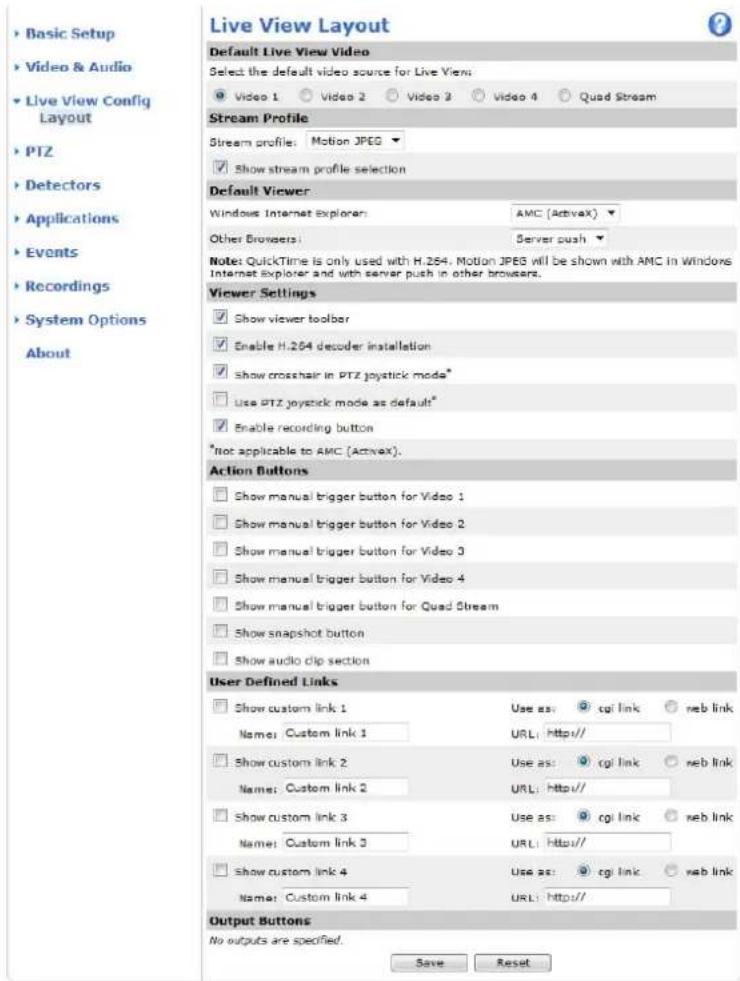
Defaultliveviewvideo
Select the default video source to be displayed in the Live View page from Setup > Live View Config This could be one of the 4 videostreamsorQuadstream.See Quadstream,onpage17 .
DefaultViewerforBrowsers
From Live View Config > Default Viewer select the default method for viewing video images in your browser. The product attempts to show the video images in the selected video format and viewer. If this is not possible, the product overrides the settings and selectsthebestavailablecombination.
| BrowserViewerDescription | ||
| WindowsInternetExplorer | AMC | RecommendedviewerinInternetExplorer(H.264/MotionJPEG) |
| QuickTime | H.264 | |
| Javaapplet | A slower imaging alternative to AMC (Motion JPEG). Requires one of the followinginstalledontheclient:•JVM(J2SE)1.4.2orhigher•JRE(J2SE)5.0orhigher | |
| Still image | Displays still images only. Click the Refresh button in your browser to view a newimage | |
| Otherbrowsers | ServerPush | Recommendedviewerforotherbrowsers(MotionJPEG). |
| QuickTime | H.264 | |
| Javaapplet | A slower imaging alternative to Server Push (Motion JPEG only). | |
| Still image | Displays still images only. Click the Refresh button in your browser to view a newimage |
Formoreinformation,pleaseetheonlinehelp.

ViewerSettings
Options for the viewer are configured under Live View Config > Viewer Settings.
- The Show viewer toolbar option will display the AXIS Media Control (AMC) or the QuickTime viewer toolbar under the videoimageinyourbrowser.
- H.264 decoder installation. The administrator can disable installation of the H.264 decoder included with AXIS Media Control. This is used to prevent installation of unlicensed copies. Further decoder licenses can be purchased from your Axisreseller.
- Select Show crosshair in PTZ joystick mode to enable a cross that will indicate the center of the image in PTZ joystick mode.
- Select Use PTZ joystick mode as default to enable joystick mode. The mode can be changed temporarily from the PTZ controlpanel.
- You can enable recording from the Live View page. The recordings are saved to the location specified in the AMC Control Panel. See AXISMediaControl(AMC),onpage12 .
UserDefined Links
To display user-defined links in the Live View page, select the Show custom link option, give the link a name and then enter the URL to link to. When defining a web link do not remove the 'http://' from the URL address. Custom links can be used to run scripts or activate external devices connected to the product, or they can link to a web page. Custom links defined as cgi links will run the script in the background, in a hidden frame. Defining the link as a web link will open the link in a new window.
OutputButtons
An output on the Axis product can be controlled directly from the Live View page, by enabling the display of output buttons. To display the output buttons in the Live View page, select the type of control to use for the port from the drop-down list under Live View Config > Output Buttons:
LiveViewConfig
- Pulse activates the output for a defined period of time. The pulse time can be set as short as 1/100 second, and as longas60seconds
- Active/Inactive displays two buttons (on/off). The output ports must first be configured under System Options> Ports & Devices > I/O Ports. See I/OPorts,onpage44
PTZ(PanTiltZoom)
InstallingaPTZdriver
This Axis product supports several PTZ devices. Please see www.axis.com for a complete list of supported devices, and to obtain the correct driver. To install a PTZ device you need to install the PTZ driver.
To install the PTZ driver go to PTZ> Driver Selection. Browse to find the driver (e.g. driver.ptz) and Upload. If the driver was successfully uploaded, it appears in the Select driver to use drop-down list. From this drop-down list, select the driver to install orremove, and clickSave.
Select Activate PTZ to enable PTZ. The address of the connected device appears against Device ID. Choose the Device type from the drop-down list. To find which device type to use, consult the documentation supplied by the PTZ driver.
To complete the installation go to System Options > Ports & Devices > COM Port (see COMPort) and verify these settings.
PresetPositions
A preset position is a predefined view that can be used to quickly steer the camera to a specific location. Preset positions can be accessed in several ways:
- Byselecting the preset from the Preset positions drop-downlist in the liveView Page.
- Whensettingupactionrules.See page31.
- WhensettingupGuardTour.See page26.
Toaddapresetposition:
- GotoPTZ>PresetPositions.
- Usethepan, tilt and zoom control, tosteer the camera view to the desired position.
- Enter a descriptive name in the Current position field.
- If required, select UsecurrentpositionasHome.
- Click Add. The camera's position, iris and focus settings are saved as a preset position.
The Home position is readily accessible by clicking the Home button on the Live View page and in the Preset Positions setup window.
To set a customized home position, select Use current position as Home when adding a preset position. The user-defined home position will have (H) added, for example, Entrance (H). The default Home position, called "Home", will still be available.
The product can be configured to return to the Home position when the PTZ functionality has been inactive for a specified length of time. Enter the length of time in the Return to home when inactive field and click Save. Set the time to zero to prevent the product from automatically returning to the Home position.
To include the preset position name in the overlay text, go to Video & Audio, select Include overlay text and enter the modifier #P in the field. For more information about modifiers, see File Naming & Date/Time Formats intheonlinehelp

GuardTour
A guard tour displays the video stream from different preset positions, one-by-one, in a predetermined order or at random and for configurable time periods. The enabled guard tour will keep running after the user has logged off or closed the browser.
Toaddaguardtour:
- Go to PTZ > Guard Tour and click Add.
2.Enteradescriptivename. - Specify the pause length between runs.
- Select an available preset position and click Apply.
- SpecifytheMovespeed.
- Specify theViewTimeinsecondsorminutes.
- Specify the View order or select the Random view order check box option.
8.ClickSave.
To modify or remove guard tours, go to PTZ > Guard Tour, select the guard tour in the Guard Tour List and click Modify/Remove.
Formoreinformationseetheonlineh elp ?
Advanced
DeviceSettings
The Dev i ctinge window displays driver specific settings. The appearance of this window can vary depending on the driver installed. Option that can be configured include:
• Driver Specific Settings from Video Source
•MechanicalLimitsforMovingVideoSource
•LightControlVideoSource
- ExtendedDriverSpecificSettingsforVideoSource
FordownloadandinstallationinformationaboutPTZdriversforyourAxisproductpleasevisitwww.axis.com/techsup/
Controls
Panel Shortcut Command Buttons can be configured to provide direct access to commands issued via the VAPIX® Application Programming Interface. The buttons will be displayed in the PTZ control panel, which is available in the Live View page through theCtrlpanelbutton,see page10.
Deselect the options under Enable/Disable controls to disable the pan, tilt, zoom, focus and iris controls.
Note
Disabling PTZ controls will not affect preset positions. For example, if the tilt control is disabled, the product can still move to presetpositionsthatrequireatiltmovement.
OSDMenu
If the PTZ unit supports an internal configuration menu, this can be accessed using the On-Screen Display (OSD). Configure the analog camera by opening and navigating through its internal menu in this display.
Applications
Third party applications can be uploaded to and installed on the Axis product. For information about available applications, downloads, trials and licenses, got www.axis.com/applications
To upload an application, go to Applications > Overview, click Browse to locate the file and then click Upload Package. Click on the uploaded application's name to open the menu options Settings, License and About. For configuration instructions, please refer to the documentation provided with the application.
Most applications need a license to run. To install the license, select the License menu option. If the product is connected to the Internet, Automatic Installation appears in the web page. If the product is not connected to the Internet, go to www.axis.com/applications to acquire a License key. You will need a license code and the product's serial number (found on the label and under System Options > Support > System Overview) to receive a license key.
Installed Applications lists installed applications with information about the version and the vendor, the status of the application (runningornotrunning), and informationaboutthelicense.
Use the Start and Stop buttons to start and stop the application.
To generate a log file for the application, select the application and click Log.
Note
It is recommended to run one application at a time. Avoid running applications when motion detection is active.
Applicationsareonlysupportedonchannel1.
Detectors
CameraTampering
Camera Tampering can generate an alarm whenever the camera is repositioned, or when the lens is covered, sprayed or severely defocused. To send an alarm, for example an email, an action rule must be set up.
Toconfiguretampering:
- GotoDetectors>CameraTampering.
- Set the Minimum duration, that is, the time that must elapse before an alarm is generated. This can help prevent false alarmsforknownconditionsthataffecttheimage.
- Select Alarm for dark images if an alarm should be generated if lights are dimmed or turned off, or if the lens is sprayed, covered, or rendered severely out of focus.
4.ClickSave.
To configure the product to send an alarm when tampering occurs:
- GotoEvents>ActionRules.
- Click Add to set up a new action rule.
- Enter a Name for the action rule.
- Under Condition, select Detectors from the Trigger list.
- SelectTamperingfromthelistofdetectors.
- Select the video channel.
- Optionally, select as schedule and set additional conditions
- Select the action. To send an email, select Send Notification and select a Recipient from the list of defined recipients.
Note
The While the rule is active option under Duration cannot be used with camera tampering, since camera tampering does not have a duration and once it has been triggered it will not automatically return to its untriggered state.
Formoreinformationonactionsrules,see Events,onpage31.
MotionDetect ion
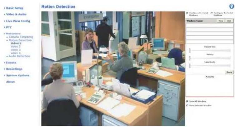
Motiondetectionisusedtogenerateanalarmwhenevermovementoccurs(orstops)intheview. Up windowscanbeconfigured:
- Include windows – target specific areas within the whole video image
- Exclude windows – define areas within an Include window that should be ignored (areas outside Include windows are automatically ignored)
Once configured, motion detection windows appear in the list of Detectors in Action rule setup. See SettingUpanActionRule, on page32.
Note
Using the motion detection feature may decrease the product's overall performance.
Detectors
AudioDetection
The Axis product can be configured to generate an alarm when audio rises above or falls below the threshold value. The threshold value can be set in the range 0–100 where 0 is the most sensitive and 100 the least sensitive.
- GotoDetectors>AudioDetection.
2.SettheaudioalarmlevelandclickSave.
- GotoEvents>ActionRulesandsetupanactionrule,see
SettingUpanActionRule, onpage32
Detected audio is indicated by colored peaks in the Activity indicator. An event is triggered when detected audio rises above or falls below the threshold value, which is represented by the bar.
Events
The Axis product can be configured to perform actions when different events occur, for example, start a recording when motion is detected. The set of conditions that defines how and when the action is triggered is called an Action Rule.
Available Action Rule triggers and conditions include:
- Applications — use installed applications to trigger the rule, see Applications,onpage28 .
- Detectors
-AudioDetection—triggertherulewhenaudioisdetected,see AudioDetection,onpage30.
- Motion Detection – trigger the rule when motion is detected, see MotionDetection,onpage29.
- Tampering – trigger the rule when tampering is detected, see CameraTampering, onpage29.
- Hardware
-VideoSignal—triggertheruleifvideosignalislost.
- Network — trigger the rule if network connection is lost or restored. This can for example be used to start recordingtotheSDcard.
- InputSignal
- Digital Input Port — trigger the rule when an I/O port receives a signal from a connected device, see I/O Ports,onpage44.
- Manual Trigger — trigger the rule using the Manual Trigger button in the Live View page, see ControlsontheLiveViewPage,onpage9 .Thiscanforexamplebeusedtovalidateactionsd uringproductinstallation andconfiguration.
•PTZ
- Moving — trigger the rule when the camera view moves due to a PTZ operation. This can for example be used as an additional condition to prevent an action rule triggered by motion detection to record video while the cameraviewmovesduetoaPTZoperation.
-PresetReached— t r i g g e r t h e r u l e when the camera stops at a preset position. This can be for example be used withtheSendImagesactiontuploadimagesfromthepresetposition.
•Storage
Available — trigger the rule when the storage device is unmounted or removed. This can for example be used to send maintenance notifications.
- Full – trigger the rule when the storage device is full. Under normal operation, the oldest recordings will be overwritten to prevent the storage device from becoming full.
-L ocked - trigger the rule if the storage device is locked (write protected).
- Storage read only — the file system is broken or the lock switch on the SD card is in locked position
•System
- System Initializing – trigger the rule when the product is being started. This can for example be used to send a notificationwhentheproductrestarts.
•Time
-Recurrence—triggertheruleperiodically,see uploadanimageevery5minutes. Recurrences,onpage33 .Thiscanforexamplebeusedto
Events
- Use Schedule – trigger the rule according to the selected schedule, see Schedules, onpage33.
Availableactionsinclude:
- Output Port – activate an I/O port to control an external device.
-PlayAudioClip—see AudioClips,onpage21 - PTZControl
-PresetPosition—gotoapresetposition.
-GuardTour-startaguardtour,see GuardTour,onpage26 .
- RecordVideo—recordvideotoaselectedstorage.
- SendImages— send imagestoarecipient.
- Send Notifications – send a notification message to a recipient.
- Status LED – flash the LED indicator. This can for example be used to validate triggers such as motion detection during productinstallationandconfiguration.
SettingUpanActionRule
An action rule defines the conditions that must be met for the product to perform an action, for example record video or send email notifications. If multiple conditions are defined, all must be met to trigger the action.
The following example describes how to set up an action rule to record video to a network share if there is movement in the camera's fieldofview.
Setupmotiondetectionandaddanetworkshare:
- Go to Detectors > Motion Detection and configure a motion detection window, see
- Go to System Options > Storage and set up the network share, see page44.
Setuptheactionrule:
- Go to Events > Action Rules and click Add.
- SelectEnableruleandenteradescriptivenamefortherule.
- Select Detectors from the Trigger drop-down list.
- Select Motion Detection from the drop-down list. Select the motion detection window to use.
- Optionally, select a Schedule and Additional conditions, see below.
- Under Actions, select Record Video from the Type drop-down list.
- Select a Stream profile and configure the Duration settings as described below.
- SelectNetworkSharefromtheStoragedrop-downlist.
To add additional criteria, select the Additional conditions option and add additional triggers. To prevent an action from being triggered repeatedly, a Wait at least time can be set. Enter the time in hours, minutes and seconds, during which the trigger should be ignored before the action rule can be activated again.
The recording Duration of some actions can be set to include time immediately before and after the event. Select Pre-trigger time and/or Post-trigger time and enter the number of seconds. When While the rule is active is enabled and the action is triggered again during the post-trigger time, the recording time will be extended with another post-trigger time period.
Formoreinformation,seetheonlinehelp
?
Recipients
Recipients receive media files and notification messages. The following recipients are available:
| RecipientUsewithaction | |
| SendImagesSendNotification | |
| FTP | SendImages |
| HTTP | SendImagesSendNotification |
| NetworkShareSendImages | |
| TCPSendNotification |
Toaddarecipient:
- Go to Events > Recipients and click Add.
2.Enteradescriptivename
3.SelectarecipientType.
4.Entertheinformationneededfortherecipienttype. - Click Test to test the connection to the recipient.
6.ClickOK.
Schedules
Schedules can be used as action rule triggers or as additional conditions, for example to record video if motion is detected outside office hours. Use one of the predefined schedules or create a new schedule as described below.
Tocreateanewschedule:
- Go to Events > Schedules and click Add.
- Enter a descriptive name and the information needed for a daily, weekly, monthly or yearly schedule.
3.ClickOK.
To use the schedule in an Action Rule, select the schedule from the Schedule drop-down list in the Action Rule Setup page.
Recurrences
Recurrences are used to trigger Action Rules repeatedly, for example every 5 minutes or every hour.
Tosetuparecurrence:
- Go to Events > Recurrences and click Add.
2.Enteradescriptivenameandrecurrencepattern.
3.ClickOK.
To use the recurrence in an Action Rule, first select Time from the Trigger drop-down list in the Action Rule Setup page and thenselecttherecurrencefromtheseconddrop-downlist.
Events
To modify or remove recurrences, select the recurrence in the Recurrences List and click Modify or Remove.
Recordings
The Axis product can be configured to record video continuously or according to an action rule:
•Tostartacontinuousrecording,see page35.
- Tosetupactionrules,see page32.
•Toaccessrecordings,see RecordingList,onpage35 .
• To configure camera controlled storage, see Storage,onpage43.
RecordingList
Recorded videos are listed on the Recordings > List page. The list shows each recording's start date and time, duration and the event that triggered therecording.
Toplayordownloadarecording, followthesesteps:
- GotoRecordings>List.
- Use the filter to narrow the list of recordings. Enter the desired filter criteria and click Filter. Some filters may take alongtimetocomplete.
- Selecttherecording.
- Click Play to play the recording, or click Download to download the recording.
Multiple recordings can be downloaded at the same time. Select the recordings and click Download. The downloaded file is a zip file containing a minimum of three files, of which the Matroska (mkv) files are the actual recordings. The recordings are time-stamped withthedateandtimetheyweredownloaded(thatis,notthedatethe recordingsweremade).
Note
To play recordings in Windows Media Player, AXIS Matroska File Splitter must be installed. AXIS Matroska File Splitter can bedownloaded from www.axis.com/techsup/software
For detailed recording and video information, select a recording and click Properties.
Toremovearecording,selecttherecordingandclickRemove.
Continuousrecording
The Axis product can be configured to continuously save video to a storage device. See Storage,onpage43 formoreinformation about storage devices. To prevent the disk from becoming full, it is recommended to configure the disk to automatically remove oldrecordings.
Tostartacontinuousrecording,followthesesteps:
- GotoRecordings>Continuous.
2.SelectEnabled. - SelecttypeofstoragedevicefromtheDisklist.
- Select a Stream profile to use for continuous recordings.
5.ClickSavetosaveandstarttherecording.
Recordings
Note
If a new stream profile is selected while a recording is ongoing, the recording will be stopped and saved in the recording list and a new recording with the new stream profile will start. All previous continuous recordings will remain in the recording list until they are removed manually or through automatic removal of old recordings.
SystemOptions
Security
Users
User access control is enabled by default and can be configured under System Options > Security > Users. An administrator can set up other users by giving them user names and passwords. It is also possible to allow anonymous viewer login, which means that anybody may access theLiveViewpage.
Theuserlistdisplaysauthorizedusersandusergroups(accesslevels):
Viewer-AccesstotheLiveViewpage
Operator-Access to theLiveView page and to all setting except System Options
Administrator – Unrestricted access to all settings; can add, modify and remove other users.
Under HTTP/RTSP Password Settings, select the type of password to allow. You may need to allow unencrypted passwords if there are viewing clients that do not support encryption, or if you upgraded the firmware and existing clients support encryption but need to login again and be configured to use this functionality.
Under User Settings, select the Enable anonymous viewer login option to allow anonymous users access to the Live View page.
Select the Enable anonymous PTZ control login to allow anonymous users access to the PTZ controls.
Deselect the Enable Basic Setup option to hide the Basic Setup menu. Basic Setup provides quick access to settings that should be made before using the Axis product.
ONVIF
ONVIF (Open Network Video Interface Forum) is a global interface standard that makes it easier for end users, integrators, consultants, and manufacturers to take advantage of the possibilities offered by network video technology. ONVIF enables interoperability between different vendor products, increased flexibility, reduced cost and future-proof systems.
Bycreatingauseryouautomatically enable ONVIF communication. Use the user name and password with all ONVIF communication with the product. Formoreinformationseewww.onvif.org
IPAddressFilter
IP address filtering is enabled on the System Options > Security > IP Address Filter page. Once enabled, the listed IP address are allowedordeniedacces s to the Axis product. Select Allow or Deny from the list and click Apply to enable IP address filtering.
The administrator can add up to 256 IP address entries to the list (a single entry can contain multiple IP addresses).
HTTPS
The Axis product supports encrypted browsing using HTTPS. This is configured on the System Options > Security > HTTPS page.
A self-signed certificate can be used until a Certificate Authority-issued certificate has been obtained. Click Create self-signed certificate to install a self-signed certificate. Although self-signed certificates are free and offer some protection, true security is only implemented after the installation of a signed certificate issued by a Certificate Authority.
To obtain a signed certificate from an issuing Certificate Authority, click Create Certificate Request. When the signed certificate is returned, click Install signed certificate to import the certificate. The properties of any certificate request currently resident in the product or installed can be viewed by clicking Properties.
To enable HTTPS in the Axis product, the HTTPS Connection Policy must be set for each user group.
Formoreinformation,seetheonlinehelp

IEEE802.1X
IEEE 802.1X is a standard for port-based Network Admission Control providing secure authentication of wired and wireless network devices.IEEE802.1XisbasedonEAP(ExtensibleAuthenticationProtocol).
To access a network protected by IEEE 802.1X, devices must authenticate themselves. The authentication is performed by a third-party entity called an authentication server, typically a RADIUS server, examples of which are FreeRADIUS and Microsoft InternetAuthenticationService.
In Axis' implementation, the network device and the authentication server authenticate themselves with the help of digital certificates using EAP-TLS (Extensible Authentication Protocol - Transport Layer Security). The certificates are provided by an Certification Authority (CA). You need:
- a CA certificate to validate the identity of the authentication server
- a CA-signed client certificate and a private key to authenticate the network device.
ToallowthenetworkdevicetoaccessanetworkprotectedbyIEEE802.1X:
- Obtain a CA certificate, a client certificate and a client private key (contact your network administrator).
- Go to Setup > System Options > Security > IEEE 802.1X and upload the CA certificate, the client certificate and the clientprivatekey.
- Under Settings, select the EAPOL version, provide your EAP identity and private key password.
- ChecktheboxtoenableIEEE802.1XandclickSave.
Certificates
| CA Certificate | The CA certificate is used to validate the identity of the authentication server. Enter the path to the certificate directly, or locate the file using theBrowsebutton. Then clickUpload. To remove a certificate, clickRemove. |
| Clientcertificate | The client certificate and private key are used to authenticate the network device. They can be uploaded as separate files or in one combined file (e.g. a PFX file or a PEM file). Use the Client private key field if uploading one combined file. For each file, enter the path to the file, orlocate the file using theBrowsebutton. Then clickUpload. To remove a file, clickRemove. |
| Clientprivatekey |
Settings
| EAPOLversion | Select the EAPOL version (1 or 2) as used in your network switch. |
| EAPidentity | Enter the user identity (maximum 16 characters) associated with your certificate. |
| Privatekeypassword | Enterthepassword(maximum 16characters)fortheprivatekey. |
| EnableIEEE802.1X | ChecktheboxtoenabletheIEEE802.1Xprotocol. |
AudioSupport
Select Enable audio support to allow clients to retrieve audio streams from the Axis product. For information on how to configure audiosettings, see AudioSettings, onpage19 .
Note
Deselecting this option will disable audio globally in the Axis product, for configured events and profiles with audio as well.
Date& Time
The Axis product's date and time settings are configured under System Options > Date & Time.
Current Server Time displays the current date and time (24h clock). The time can be displayed in 12h clock in the text overlay (see below).
To change the date and time settings, select the preferred Time mode under New Server Time:
- Synchronize with computer time sets date and time according to the computer's clock. With this option, date and timearesetonceandwillnotbeupdatedautomatically.
- Synchronize with NTP Server obtains date and time from an NTP server. With this option, date and time settings are updated continuously. For information on NTP settings, see NTPConfiguration, on page 40.
If using a host name for the NTP server, a DNS server must be configured. See DNSConfiguration,onpage40 . - Set manually allows you to manually set date and time.
If using an NTP server, select your Time zone from the drop-down list. If required, check Automatically adjust for daylight saving timechanges.
The Date & Time Format Used in Images is the date and time format displayed as a text overlay in the video stream. Use the predefined formats or see FileNaming&Date/TimeFormats in the online help form information on how to create custom date and time formats. To include date and time in the overlay text, go to Video & Audio and select Include date and Include time.
Network
BasicTCP/IPSettings
The Axis product supports IP version 4 and IP version 6. Both versions can be enabled simultaneously, and at least one version mustalwaysbeenabled.
IPv4AddressConfiguration
By default, the Axis product is set to use IPv4 (IP version 4) and to obtain the IP address automatically via DHCP. The IPv4 settings are configured under System Options > Network > TCP/IP > Basic.
DHCP (Dynamic Host Configuration Protocol) allows network administrators to centrally manage and automate the assignment of IP addresses. DHCP should only be enabled if using dynamic IP address notification, or if the DHCP can update a DNS server. It is then possible to access the Axis product by name (hostname).
If DHCP is enabled and the product cannot be accessed, run AXIS IP Utility to search the network for connected Axis products, or reset theproducttothefactorydefaultsettings(see page47)andthenperformtheinstallationagain.
To use a static IP address, check Use the following IP address and specify the IP address, subnet mask and default router.
IPv6AddressConfiguration
If IPv6 (IP version 6) is enabled, the Axis product will receive an IP address according to the configuration in the network router.
To enable IPv6, go to System Options > Network > TCP/IP > Basic. Other settings for IPv6 should be configured in the network router.
ARP/Ping
The IP address can be set using ARP and Ping. For instructions, see the product's Installation Guide.
ARP/Ping is enabled by default. To disable, uncheck the box under System Options > Network > TCP/IP > Basic.
The ARP/Ping service is automatically disabled two minutes after the product is started, or as soon as an IP address is set. To reset the IP address, the product must be restarted to activate ARP/Ping for an additional two minutes.
Pinging the product is still possible when this service is disabled.
SystemOptions
AXISVideoHostingSystem(AVHS)
AVHS used in conjunction with an AVHS service, provides easy and secure Internet access to live and recorded video accessible from any location. For more information and help to find a local AVHS Service Provider go to www.axis.com/hosting
AVHS is enabled by default. The settings are configured under System Options > Network > TCP IP > Basic.
One-clickenabled-Presstheproduct'scontrolbutton(see HardwareOverview,onpage5)toconnecttoanAVHSserviceoverthe Internet. Once registered, Always will be enabled and the Axis product stays connected to the AVHS service. If the product is not registered within 24 hours from when the button is pressed, the product will disconnect from the AVHS service.
Always - The Axis product will constantly attempt to connect to the AVHS service over the Internet. Once registered the product will stay connected to the service. This option can be used when the product is already installed and it is not convenient to use the one-click installation.
AXISInternetDynamicDNSService
AXIS Internet Dynamic DNS Service assigns a host name for easy access to the product. For more information, see www.axiscam.net
To register the Axis product with AXIS Internet Dynamic DNS Service, go to System Options > Network > TCP/IP > Basic. Under Services, click the AXIS Internet Dynamic DNS Service Settings button (requires access to the Internet). The domain name currently registered at AXIS Internet Dynamic DNS service for the product can at any time be removed.
AdvancedTCP/IPSettings
DNSConfiguration
DNS (Domain Name Service) provides the translation of host names to IP addresses. The DNS settings are configured under System Options>Network>TCP/IP>Advanced.
Select Obtain DNS server address via DHCP to use the DNS settings provided by the DHCP server.
To make manual settings, select Use the following DNS server address and specify the following:
Domain name - Enter the domain(s) to search for the host name used by the Axis product. Multiple domains can be separated by semicolons. The host name is always the first part of a fully qualified domain name, for example, myserver is the host name in the fully qualified domain name myserver.mycompany.com where mycompany.com is the domain name.
Primary/Secondary DNS server - Enter the IP addresses of the primary and secondary DNS servers. The secondary DNS server is optionalandwillbeusediftheprimaryisunavailable.
NTPConfiguration
NTP (Network Time Protocol) is used to synchronize the clock times of devices in a network. The NTP settings are configured under SystemOptions>Network>TCP/IP>Advanced.
Select Obtain NTP server address via DHCP to use the NTP settings provided by the DHCP server.
To make manual settings, select Use the following NTP server address and enter the host name or IP address of the NTP server.
HostNameConfiguration
The Axis product can be accessed using a host name instead of an IP address. The host name is usually the same as the assigned DNS name. The host name is configured under System Options > Network > TCP/IP > Advanced.
Select Obtain host name via IPv4 DHCP to use host name provided by the DHCP server running on IPv4.
SelectUsethehostnametosetthehostnamemanually.
Select Enable dynamic DNS updates to dynamically update local DNS servers whenever the Axis product's IP address changes.
Formoreinformation,seetheonlinehelp

Link-LocalIPv4Address
Link-Local Address is enabled by default and assigns the Axis product an additional IP address which can be used to access the product from other hosts on the same segment on the local network. The product can have a Link-Local IP and a static or DHCP-suppliedIPaddressatthesametime.
This function can be disabled under System Options > Network > TCP/IP > Advanced.
HTTP
The HTTP port used by the Axis product can be changed under System Options > Network > TCP/IP > Advanced. In addition to the default setting, which is 80, any port in the range 1024–65535 can be used.
HTTPS
The HTTPS port used by the Axis product can be changed under System Options > Network > TCP/IP > Advanced. In addition to the default setting, which is 443, any portion in the range 1024–65535 can be used.
To enable HTTPS, go to System Options > Security > HTTPS. For more information, see page37.
NATtraversal(portmapping)forIPv4
A network router allows devices on a private network (LAN) to share a single connection to the Internet. This is done by forwarding network traffic from the private network to the "outside", that is, the Internet. Security on the private network (LAN) is increased since most routers are pre-configured to stop attempts to access the private network (LAN) from the public network (Internet).
Use NAT traversal when the Axis product is located on an intranet (LAN) and you wish to make it available from the other (WAN) side of a NAT router. With NAT traversal properly configured, all HTTP traffic to an external HTTP port in the NAT router is forwarded to the product.
NAT traversal is configured under System Options > Network > TCP/IP > Advanced.
Note
- For NAT traversal to work, this must be supported by the router. The router must also support UPnPTM.
- The router has many different names: "NAT router", "Network router", "Internet Gateway", "Broadband router", "Broadband sharing device" or "Home firewall" but the essential purpose of the device is the same.
Enable/Disable - When enabled, the Axis product attempts to configure port mapping in a NAT router on your network, using UPnP ^TM . NotethatUPnP ^TM must be enabled in the product (see System Options > Network > UPnP).
Use manually selected NAT router - Select this option to manually select a NAT router and enter the IP address for the router in the field. If no router is specified, the product automatically searches for NAT routers on your network. If more than one router is found, the defaultrouter is selected.
Alternative HTTP port - Select this option to manually define an external HTTP port. Enter the port number in the field. If no port is entered here, a port number is automatically selected when NAT traversal is enabled.
Note
- An alternative HTTP port can be used or be active even if NAT traversal is disabled. This is useful if your NAT router does not support UPnP and you need to manually configure port forwarding in the NAT router.
- If you attempt to usually enter a port that is already in use, another available port is automatically selected.
- When the port is selected automatically it is displayed in this field. To change this, enter a new port number and click Save.
FTP
The FTP server running in the Axis product enables upload of new firmware, user applications, etc. The FTP server can be disabled under System Options > Network > TCP/IP > Advanced.
Note
This FTP server has nothing to do with the product's ability to transfer images via FTP to other locations and servers.
RTSP
The RTSP server running in the Axis product allows a connecting client to start an H.264 stream. The RTSP port number can be changed under System Options > Network > TCP/IP > Advanced. The default port is 554.
Note
H.264 video streams will not be available if the RTSP server is disabled.
SOCKS
SOCKS is a networking proxy protocol. The Axis product can be configured to use a SOCKS server to reach networks on the other side of a firewall or proxy server. This functionality is useful if the Axis product is located on a local network behind a firewall, and notifications, uploads, alarms, etc need to be send to a destination outside the local network (for example the Internet).
SOCKS is configured under System Options > Network > SOCKS. For more information, see the online help ?
QoS(QualityofService)
QoS (Quality of Service) guarantees a certain level of a specified resource to selected traffic on a network. A QoS-aware network prioritizes network traffic and provides a greater network reliability by controlling the amount of bandwidth an application may use.
The QoS settings are configured under System Options > Network > QoS. Using DSCP (Differentiated Services Codepoint) values, the Axis product can mark the following types of traffic: live video, live audio, event/alarm traffic and management traffic.
Note
LiveaudioDSCPwillbeequaltolivevideoDSCPifH.264overRTSPisused.
SMTP(email)
To send email messages from the Axis product via SMTP (Simple Mail Transfer Protocol), an SMTP mail server must be set up. This is done under SystemOptions>Network>SMTP(email).
Enter the host names or IP addresses and port numbers for the primary and secondary mail servers in the fields provided. A From emailaddressisalsorequired.Ifthemailserverrequiresa authentication, check Use authentication to log in to this server and enter thenecessaryinformation.
SNMP
The Simple Network Management Protocol (SNMP) allows remote management of network devices. An SNMP community is the groupofdevicesandmanagementstati onrunningSNMP.Communitynamesareusedtoidentifygroups.
TheAxisproductcanbeconfigured to support SNMP on the System Options > Network > SNMP page.
Dependingonthelevelofsec urityrequired,selecttheversiononSNMPtouse.
SNMPv1/v2provide the lowest level of security. The community name can be specified as a password for read or read/write access to all supported SNMP devices. The default password for the Read community is public and the default password for the Writecommunityiswrite.
Note
If HTTPSisenabled, SNMPv1 and SNMPv2 should be disabled.
Traps for SNMP v1/v2 are used by the Axis product to send messages to a management system on important events and status changes. Check Enable traps and enter the IP address where the trap message should be sent and the Trap community that should receive them message.
The followingtrapsareavailable:
• C o l d s t a r t
- Warm start
- Link up
- Authenticationfailed
SNMP v3 provides encryption and secure passwords. To use traps with SNMP v3, an SNMP v3 management application is required.
TouseSNMPv3, HTTPSmustenabled,see HTTPS,onpage37 .ToenableSNMPv3,checktheboxandprovidetheinitialuser password.
Note
The initial password can only be set once. If the password is lost, the Axis product must be reset to factory default, see ResettoFactoryDefaultSettings, onpage47
UPnPTM
TheAxisproductincludessupportforUPnP ^TM . UP n ^Tpl isenabledbydefaultandtheproductisautomaticallydetectedbyoperating systemsandclientsthatsupportthisprotocol.
UPnP ^TM can be disabled under System Options > Network > UPnP ^TM .
RTP/H.264
The RTP port range and multicast settings are configured under System Options > Network > RTP.
The RTP port range defines the range of ports from which the video/audio ports are automaticallyselected.Formulticaststreams, onlycertainIPaddressesandportnumbersshouldbeused.
Select Always Multicast Video and/or Always Multicast Audio to start multicast streaming without opening an RTSP session.
Bonjour
The Axis product includes support for Bonjour. Bonjour is enabled by default and the product is automatically detected by operating systemsandclientsthatsupportthisprotocol.
BonjourcanbedisabledunderSystemOp tions>Network>Bonjour.
Storage
SDCard
NOTICE
To prevent corruption of recordings, the SD card should always be unmounted before it is ejected.
The Axis product supports SD cards with the following file systems:
- ext4 — recommended due to its resilience against data loss if the card is ejected or if there is abrupt power loss. To access data stored on the card from the Windows operating system, a third-party ext4 driver or application is required.
- vFAT – most SD cards are pre-formatted with vFAT when purchased.
If required, the SD card can be re-formatted to the desired file system. To format the SD card:
-
Insert the SD card in the SD card slot.
-
Go to System Options > Storage and click SD Card.
SystemOptions
- Click Format and select the desired file system.
Note
During formatting any previous data stored on the disk will belost.
Mounting is done automatically when the card is inserted or when the product is started. A manual mount is only required if the cardhasbeenunmountedandnotejectedandre-inserted.
TounmounttheSDcard:
- Go to System Options > Storage and click SD Card.
2.ClickUnmount. - The cardcannowbeejected.
The SD card is managed on the System Options > Storage page. Click SD Card to open Storage Management.
If the card's status shows as failed, click Check disk to see if the problem can be found and then try Repair. This option is only available for SD cards with ext4. For SD cards with vFAT, use a card reader or computer to troubleshoot the card.
To avoid filling the card, it is recommended to remove recordings continuously. Under Recording Settings, select Remove recordings olderthanandselectthenumberofdaysorweeks.
To stop writing to the card and protect recordings from being removed, select Lock under Recording Settings.
NetworkShare
Network share allows you to add network storage such as a NAS (Network Attached Storage) or any server that uses CIFS (Common InternetFileSystem) and usethemforstorageofrecordings.
Toaddanetworkshare:
- GotoSystemOptions>Storage.
2.ClickNetworkShare. - Enter the IP address, DNS or Bonjour name to the host server in the Host field.
- Enter the name of the share in the Share field.
- If required, select The share requires login and enter the user name and password.
6.ClickConnect.
To clear all recordings and data from the Axis product's folder on the designated share, click Clear under Storage Tools.
To avoid filling the share, it is recommended to remove recordings continuously. Under Recording Settings, select Remove recordings olderthanandselectthenumberofdaysorweeks.
To stop writing to the share and protect recordings from being removed, select Lock under Recording Settings.
Ports&Devices
I/OPorts
The Axis product provides four configurable input and output ports for connection of external devices. For information on how to connect external devices, see Connectors, onpage5 .
The I/O ports are configured under System Options > Ports & Devices > I/O Ports. Select the port direction (Input or Output). The ports can be given descriptive names and their Normal states can be configured as Open circuit or Grounded circuit.
COMPort
ThevideoencoderhasoneRS-485/RS-422serialport.Theportsupportsthefollowingmodes:
- Generic HTTP allows the video encoder to receive data and send commands via HTTP.
- Pan Tilt Zoom is used to control a PTZ device. The PTZ device requires a driver. See InstallingaPTZdriver formore information.Driverscanbedownloadedfromwww.axis.com
- Generic TCP/IPallows the Axis product to receive data and send commands via TCP/IP. Daisy chain server - Allows Daisy chain clients to communicate with the Axis product. See also RS-485/RS-422 connector, on page 43.
Select the desired Port Type from the drop-down list. For more information on Serial Port Settings and Daisy Chain Port Settings seetheonline.help
PortStatus
The list on the System Options > Ports & Devices > Port Status page shows the status of the product's input and output ports.
Maintenance
The Axis product provides several maintenance functions. These are available under System Options > Maintenance.
Click Restart to perform a correct restart if the Axis product is not behaving as expected. This will not affect any of the current settings.
Click Restore to reset most settings to the factory default values. The following settings are not affected:
•thebootprotocol(DHCPorstatic)
- thestaticlPaddress
- thedefaultrouter
- thesubnetmask
- the system time
•theIEEE802.1Xsettings
Click Default to reset all settings, including the IP address, to the factory default values. This button should be used with caution. The Axis product can also be reset to factory default using the control button, see ResettoFactoryDefaultSettings, onpage47 .
To identify the product or test the Status LED, click Flash LED under Identify and specify the duration in seconds, minutes or hours. This can be useful for identifying the product among other products installed in the same location.
For information about firmware upgrade, see UpgradingtheFirmware,onpage48 .
SystemOptions
![Server Maintenance Maintain Server Restart Restart the AXIS Q7424-X Video Encoder. Restor Resets all parameters, except the IP parameters, to the original factory settings. Default Assets all parameters to the original factory settings. Upgrade Server Upgrade the AXIS Q7424-X with the latest firmware. Specify the firmware to upgrade to: Browse... and click Upgrade Note: Do not disconnect power to the unit during the upgrade. The unit restarts automatically after the upgrade has completed. (1-10 minutes.) Identify Flash LED for 10 seconds ▼ [L..50] Basic Setup Video & Audio Live View Config PTZ Detectors Applications Events Recordings System Options Security Date & Time Network Storage Ports & Devices Maintenance Support Advanced About](/content/2026/05/1046863/images/02fed51c4160a4386815ef03fcb61e0ea006df23a48e61e555845ec8c7c1a081.jpg)
Support
SupportOverview
The System Options > Support > Support Overview page provides information on troubleshooting and contact information, should you require technical assistance.
Seealso Troubleshooting, onpage48
SystemOverview
To get an overview of the Axis product's status and settings, go to System Options > Support > System Overview. Information that can be found here includes firmware version, IP address, network and security settings, event settings, image settings and recent log items. ManyofthecaptionsarelinkstotheproperSetuppage.
Logs&Reports
The System Options > Support > Logs & Reports page generates logs and reports useful for system analysis and troubleshooting. If contactingAxisSupport, please provide a valid Server Report with your query.
SystemLog-Providesinformationaboutsystemevents.
Access Log - Lists all failed attempts to access the product. The Access Log can also be configured to list all connections to the product(seebelow).
Server Report – Provides information about the product status in a pop-up window. The Access Log is automatically included intheServerReport.
Youcanviewordownloadthe server report. Downloading the server report creates a .zip file that contains a complete server report text file in UTF-8 format. Select the Include snapshot with default image settings option to include a snapshot of the product's Live View that also shows the settings specified under Video Stream>Image>Image Appearance. The server report .zip file should alwaysbeinclude d when contactingsupport.
ParameterLis t - Shows the product's parameters and their current settings. This may prove useful when troubleshooting or whencontactingAxisSupport.
Connection List – Lists all clients that are currently accessing media streams.
Crash Report - Generates an archive with debugging information. The report takes several minutes to generate.
The log levels for the System Log and the Access Log are set under System Options > Support > Logs & Reports > Configuration. The Access Log can be configured to list all connections to the product (select Critical, Warnings & Info). If required, a different log level can be used when sending emails.
Advanced
Scripting
Scripting allows experienced users to customize and use their own scripts.
NOTICE
Improper use may cause unexpected behavior and loss of contact with the Axis product.
Axis strongly recommends that you do not use this function unless you understand the consequences. Axis Support does not provide assistance for problems with customized scripts.
To open the Script Editor, go to System Options > Advanced > Scripting. It is recommended to create a backup file before customizing the scripts. If a script causes problems, reset the product to its factory default settings, see page47.
Formoreinformation,seewww.axis.com/developer
FileUpload
Files, for example web pages and images, can be uploaded to the Axis product and used as custom settings. To upload a file, go toSystemOptions>Advanced>FileUpload.
Uploaded files are accessed through http://
PlainConfig
Plain Config is for advanced users with experience of Axis product configuration. Most parameters can be set and modified from this page.Helpisavailablefromthestandardhelppages.
To open Plain Config, go to System Options > Advanced > Plain Config.
ResettoFactoryDefaultSettings
This will reset all parameters, including the Paddress, to the factory default settings:
- Disconnectpowerfromtheproduct.
- PressandholdtheControlbuttonandreconnectpower(see HardwareOverview, onpage5 ).
- Keep the Control button pressed for about 15 seconds until the Status indicator flashes amber.
- ReleasetheControlbutton. The process is complete after about 1 minute (when the status indicator turns green). The product has been reset to the factory default settings. The default IP address is 192.168.0.90
- Re-assignthelPaddress.
It is also possible to reset parameters to factory default via the web interface. Go to Setup > System Options > Maintenance.
Troubleshooting
CheckingtheFirmware
Firmware is software that determines the functionality of network devices. One of your first actions when troubleshooting a problem should be to check the current firmware version. The latest version may contain a correction that fixes your particular problem. The current firmware version in the Axis product is displayed in the page Setup > Basic Setup and in Setup > About.
UpgradingtheFirmware
When you upgrade the product with the latest firmware from Axis website, the product receives the latest functionality available. Always read the upgrade instructions and release notes available with each new release, before upgrading the firmware.
Toupgrade, follow these instructions:
- Save the firmware file to your computer. The latest version of the firmware is available free of charge from Axis website atwww.axis.com/techsup
- Go to Setup > System Options > Maintenance in the products web pages.
- Under Upgrade Server, click Browse and locate the file on your computer. Click Upgrade.
After starting the upgrade process, always wait at least 5–10 minutes before restarting the product, even if you suspect the upgrade has failed.
AXIS Camera Management can be used for multiple upgrades. See www.axis.com for more information.
Note
- Your dealer reserves the right to charge for any repair attributable to faulty upgrade by the user.
- Preconfigured and customized settings are saved when the firmware is upgraded (providingthefeaturesareavailablein the new firmware) although this is not guaranteed by Axis Communications AB.
EmergencyRecoveryProcedure
If power or network connection is lost during the upgrade, the process fails and the product becomes unresponsive. Flashing red Status indicator indicates a failed upgrade. To recover the product, follow the steps below. The serial number is found on the product's label.
- In UNIX/Linux, typethefollowing from the commandline:
arp -s <IP address> <serial number> temp
ping-s 408<IP address>
In Windows, type the following from a command/DOS prompt (this may require that you run the command prompt as an administrator):
arp-s <IPaddress> <serialnumber>
ping-1 408-t <IPaddress>
- If the product does not reply in 30 seconds, restart it and wait for a reply. Press CTRL+C to stop Ping.
- Open a browser and type in the product's IP address. In the page that appears, use the Browse button to select the upgrade file to use. Then click Load to restart the upgrade process.
- After the upgrade is complete (1–10 minutes), the product automatically restarts and shows a steady green on the Status indicator.
- Reinstall the product, referring to the Installation Guide.
If the emergency recovery procedure does not get the product up and running again, contact Axis support at www.axis.com/techsup/
Symptoms, Possible Causes and Remedial Actions
ProblemssettingthelPaddress
| WhenusingARP/Ping | Trytheinstallationagain.TheIPaddressmustbesetwithintwominutesafterpowerhasbeen appliedtotheproduct.EnsurethePinglengththissetto408.SeethelInstallationGuidefor detailedinstructions. |
| Theproductislocatedona differentsubnet | IfthelPaddressintendedfortheproductandthelPaddressofthecomputerusedtoaccessthe product are located on different subnets, you will not be able to set the IP address. Contact your networkadministratortoobtainanIPaddress. |
| ThelPaddressisbeingused byanotherdevice | Disconnect the Axis product from the network. Run the Ping command (in a Command/DOS window, type ping and the IP address of the product:If y o r e c i v e : Replyfrombytes=32;time=10... this means that the IP address may already be in use by another device on the network. ObtainanewIPaddressfromthenetworkadministratorandreinstalltheproduct.If you receive: Request timed out, this means that the IP address is available for usewiththeAxisproduct.Checkallcablingandreinstalltheproduct. |
| PossibleIPaddressconflict withanotherdeviceonthe same subnet. | The static IP address in the Axis product is used before the DHCP server sets a dynamic address. This means that if the same default static IP address is also used by another device, there may beproblemsaccessingtheproduct. |
| Theproductcannotbeaccessedfromabrowser | |
| Cannotlogin | When HTTPS is enabled, ensure that the correct protocol (HTTP or HTTPS) is used when attempting to log in. You may need to manually type http or https in the browser's address field.Ifthepasswordforrootislost,theproductmustberesettothefactorydefaultsettings.See ResettoFactoryDefaultSettings,onpage47 . |
| ThelPaddresshasbeen changedbyDHCP | If the product and the client are on the same network, run AXIS IP Utility to locate the product. Identifytheproductusingitsmodelorserialnumber.MovetheAxisproducttoanisolatednetwork,ortoonewithnoDHCPorBOOTPserver.SettheIP address again, using AXIS IP Utility or ARP/Ping (see the Installation Guide). Open the Setup pages anddisabledDHCPintheTCP/IPsettings.Returntheproducttothemainnetwork.Theproduct nowhasafixedIPaddresssthatwillnotchange. |
| Certificateerrorwhenusing IEEE802.1X | Forauthenticationtoworkproperly,thedateandtimesettingsintheAxisproductshouldbe synchronizedwithanNTPserver.See Date &Time,onpage38 . |
| Theproductisaccessiblelocallybutnotexternally | |
| Router configuration | To configure your router to allow incoming data traffic to the Axis product, enable the NAT-traversal feature which will attempt to automatically configure the router to allow access to the Axis product,see NATtraversal(portmapping)forIPv4,onpage41 .TheroutermustsupportUPnP TM. |
| Firewallprotection | ChecktheInternetfirewallwithyournetworkadministrator. |
| Defaultrouter s required | Checkifyouneedtoconfiguretheroutersettings. |
| ProblemswiththeH.264format | |
| NoH.264displayedinthe client | Check that the relevant H.264 connection methods and correct interface are enabled in the AMC Control Panel (streaming tab). See AXISMediaControl(AMC),onpage12 .In the AMC Control Panel, select the H.264 tab and click Set to default H.264 decoder.Check that RTSP is enabled under System Options > Network > TCP/IP > Advanced. |
Troubleshooting
| NomulticastH.264displayedintheclient | Check with your network administrator that the multicast addresses used by the Axis product arevalidforyournetwork. |
| Check with your network administrator to see if there is a firewall preventing viewing. | |
| MulticastH.264onlyaccessiblebylocalclients | Checkifyourroutersupportsmulticasting,orifteroutersettingsbetweentheclientandthe product need to be configured. The TTL (Time To Live) value may need to be increased. |
| PoorrenderingofH.264images | Color depth set incorrectly on clients. Set to 16-bit or 32-bit color. |
| Iftextoverlaysareblurred,orifthereareotherrenderingproblems,youmayneedtoenable Advanced Video Rendering fromv the Video tab in the AMC Control Panel. | |
| Ensure that your graphics card is using the latest driver. The latest drivers can usually be downloadedfromthemanufacturer'swebsite. | |
| ColorsaturationisdifferentinH.264andMotionJPEG | Modify the settings for your graphics adapter. Refer to the adapter's documentation for more information. |
| Lowerframeratethanexpected | Reducethenumberofapplicationsrunningontheclientcomputer. |
| Limitthenumberofsimultaneousviewers. | |
| Checkwiththenetworkadministratorthatthereisenoughbandwidthavailable. | |
| CheckintheAMCControlPanel(H.264tag)thatvideoprocessingisNOTsettoDecodeonly keyframes. | |
| Lowertheimageresolution. | |
| Whydolnotgetmaximumframespersecond? | SeePerformanceConsiderations,onpage56 . |
| Imagedegeneration | Decrease the GOV length. Go toVideo & Audio >Video Streamand select the H.264 tab tomodifytheGOVlength. |
StatusandNetworkindicatorLEDsareflashingredr rapidly
| Hardwarefailure | ContactyourAxisreseller. |
| Status indicator LED is flashing red and the product is inaccessible | |
| Afirmwareupgradehas beeninterruptedorthe firmwarehasotherwisebeen damaged | See EmergencyRecoveryP rocedure,onpage48 . |
| Noimagesdisplayedonwebpage | |
| ProblemswithAXISMedia Control(InternetExplorer only) | ToenabletheupdatingofvideoimagesinInternetExplorer,setthebrowsertoallowActiveX controls. Also, make sure that AXIS Media Control is installed on your computer. |
| Installationofadditional ActiveXcomponent restrictedorprohibited | Configure the Axis product to use a Java applet for updating video images in Internet Explorer. Go to Setup > Live View Config and select Java applet under Default viewer. |
| Videoandimageproblems,general | |
| Imagetoodarkortoolight | Check the video stream and camera settings under Setup > Video & Audio > Video Stream and Setup>Video&Audio>CameraSettings. |
| Missing images in uploads | This can occur when trying to use a larger image buffer than is actually available. Try lowering theframerateorthepuploadperiod. |
Troubleshooting
| Slow image update | Configuring pre-buffers, motion detection, high-resolution images or high frame rates will affect theperformanceoftheAxisproduct. |
| Poor performance | Poor performance may be caused by heavy network traffic, multiple users accessing the product, low performance clients, use of features such as motion detection, event handling or uploaded applications. |
| Poorqualitysnapshotimages | |
| Screenincorrectly configuredonyourcomputer | Configure your screen to show at least 65000 colors, that is, at least 16 bits. Using only 16 or 256 colorswillproduceditheringartifactsintheimage. |
| Overlayimageisnotdisplayed | |
| Incorrectsizeorlocationof overlayimage | The overlay image may have been positioned incorrectly or may be too large. See OverlayImage Settings in the online help for more information. |
| Privacymaskisnotdisplayed | |
| Incorrectsizeorlocationof privacymask | Theprivacymaskmayhavebeenpositionedincorrectlyormaybetoolarge. |
| Browserfreezes | |
| Firefoxcansometimes freezeonaslowcomputer | Lowertheimageresolution |
| Problemsuploadingfiles | |
| Limited space | There is only limited space available for the upload of your own files. Delete existing files to free upspace. |
| MotionDetectiontriggersunexpectedly | |
| Changesinluminance | Motion detection is based on changes in luminance in the image. This means that if there are sudden changes in the lighting, motion detection may trigger mistakenly. Lower the sensitivity settingtoavoidproblemswithluminance. |
| Noaudio | |
| Incorrectsetup | Check the sound card in the computer. Ensure that mute is not selected and that the volume settingsarecorrect. |
| Noaudioorverypooraudio quality | Check that Enable audio support is selected under Setup > System Options > Security > Audio Support.Check that the correct Audio Input source is selected under Setup > Video & Audio > Audio Settings. |
| Pooraudioquality | |
| CPUoverloaded | Reduce the number of listeners and viewers. Decrease image resolution and compression. |
| Unsynchronizedaudioand video | Synchronize the product's date and time settings with an NTP server. Go to Setup > System Options>Date&Time. |
Troubleshooting
| Distortedaudio | Check that the correct Audio Input source is selected under Setup > Video & Audio > Audio Settings. |
| Feedback loops | Feedback loops might appear in full-duplex mode. Try moving the microphone or the speaker, or usehalf-duplexmodeinstead. |
Storageanddiskmanagementproblems
| Videocannotberecorded | CheckthattheSDcardisnotwriteprotected(thatis,readonly). |
| SDcardcannotbemountedReformattheSDcardandthenclickMount. | |
TechnicalSpecifications
| Function/group | Item | Specifications |
| VideoEncoderModel | AXISQ7424-R(4channels) | |
| Video | Video compression | H.264 (MPEG-4 Part 10/AVC) Baseline Profile (BP) and Main Profile (MP) MotionJPEG |
| Resolutions | 176x120to720x576176x120to1536x1152forquadview | |
| FramerateH.264 | 30/25(NTSC/PAL)fps15fpsinquadviewinfullresolution | |
| Framerate MotionJPEG | 30/25(NTSC/PAL)fps15fpsinquadviewinfullresolution | |
| Videostreaming | Multi-streamH.264andMotionJPEG:OneH.264andoneJPEGstreamoneachchannel (8 streams in total) in full framerate individually configured streams in max. resolution at 30/25fps;morestreamsifidenticalorlimitedinframerate/resolutionControllableframerateandbandwidthVBR/CBRH.264 | |
| Pan/Tilt/Zoom | WiderangeofanalogPTZcamerassupported(driversavailablefordownloadat www.axis.com)100presets/camera,guardtour,PTZcontrolqueueSupportsWindowscompatiblejoysticks | |
| Imagesettings | Compression,color,brightness,contrastRotation:90°,180°,270°AspectratiocorrectionMirroringofimagesTextandimageoverlayPrivacymaskEnhanceddeinterlacefilterVideoterminationAnti-aliasingTemporalnoisefiltering | |
| Audio | AudiostreamingTwo-way | |
| Audio compression | AAC-LC8/16kHz,G.711PCM8kHz,G.726ADPCM8kHzConfigurablebitrate | |
| Audio input/output | Oneexternalmicrophoneonlineinputsandonelineoutput | |
| Network | SecurityPasswordprotec tion, IP address filtering, HTTPS* encryption, IEEE 802.1X network access control,digestauthentication,useraccesslog | |
| Supported protocols | IPv4/v6,HTTP,HTTPS*,QoSlayer3DiffServ,FTP,SMTP,Bonjour,UPnP, SNMPv1/v2c/v3(MIB-II),DNS,DynDNS,NTP,RTSP,RTP,TCP,UDP,IGMP,RTCP,ICMP, DHCP,ARP,SOCKS | |
TechnicalSpecifications
| Function/group | Item | Specifications |
| System Integration | Application Programming Interface | Open API for software integration, including the ONVIF specification available at www.onvif.org, as well as VAPIX® and AXIS Camera Application Platform from Axis Communications, specifications available at www axis.comSupportforAXISVideoHostingSystem(AVHS)withOne-ClickCameraconconnection |
| Intelligent video | Video motion detection, active tampering alarm, audio detectionSupportforAXISCameraApplicationPlaformononechannel | |
| AlarmtriggersIntelligentvideo,externalinputs,videoloss | ||
| Alarm actions | File upload via FTP, HTTP and emailNotification via email, HTTP and TCPPTZpresetExternaloutputactivationVideoandaudiorecordingtoedgestoragePre-andpost-alarmvideobuffering | |
| General | CasingStandalonealuminumcasing | |
| Processor, memory | ARTPEC-4,512MBRAM,128MBFlash | |
| Power | 8-28VDC,20-24VAC;PoweroverEthernetIEEE802.3afClass3 | |
| Connectors | 4xanalogcompositevideoinputs(BNC)1xmonomicrophoneorlineinput,6Vppmax(terminalblock)1xmonoaudiooutput,2Vppmaxat1kohm(terminalblock)1x10BASE-T/100BASE-TXEthernet4xConfigurableexternalinputs/outputs(terminalblock)1xRS-485/422fullduplex(terminalblock)1xAC/DCinputterminalblock1x1GbpsSFPslot | |
| Localstorage | 1xSD/SDHCmemorycardslot(cardnotincluded) | |
| Operating conditions | -40to+75°C(-40to+167°F)Humidity10-95%RH(non-condensing) | |
| Approvals | EN55022ClassB,EN61000-3-2,EN61000-3-3,EN55024,EN61000-6-1,EN61000-6-2,FCCPart15SubpartBClassB,ICES-003ClassB,VCCIClassB,C-tickAS/NZSCISPR22,KCCClassB,EN50121-4,EN50155(vibrationandshockcategory1 Class B, Temperature Class TX), Nema TS 2 (vibration, shock, temperature, humidity)IEC60068-2-1,IEC60068-2-2,IEC60068-2-14,IEC60068-2-27,IEC60068-2-30,IEC60068-2-64,IEC60068-2-78,CEN/TS45545-2,UL/IEC/EN60950-1 | |
| Weight | 0.8kg(1.7lb) | |
| Included accessories | Installation Guide, CD with installation and management tools, software and User's Manual,4Windowsdecoderuserlicense | |
| Optional accessories | PowerSupply(AXIST8006APS12)T8604MediaConverterSwitchDINRailClip(T91A03) | |
| Dimensions (HxWxD) | 45x135x167mm(1.8"x5.3"x6.6") | |
Connectors
I/Oterminalconnector
6-pinterminalblockfor:
- DigitalInput
- DigitalOutput
•Auxiliarypowerandground(GND)
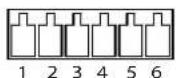
| FunctionPinNotes | Specifications | ||
| GND | 1 | Ground | |
| 12VDCPower | 2 | Canbeusedtopowerauxiliaryequipment. Note:Thispincanonlybeusedaspowerout. | Maxload=125mA |
| (InputorOutput) | 3-6 | Digitalinput-ConnecttoGNDtoactivate,orleavefloating (unconnected)todeactivate. | 0 to + 30 V D C Configurable |
| Digitaloutput-Internalconnectiontogroundwhen activated,floating(unconnected)whendeactivated.If usedwithaninductiveload,e.g.arelay,adiodemustbe connected in parallel with the load, for protection against voltagetransients. | Maxload=100mA Maxvoltage=+30VDC |

TechnicalSpecifications
Powerconnector
3-pinterminalblockforpowerinput.
DCpowerinput
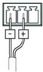
ACpowerinput
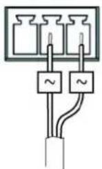
Audioconnector
4-pinterminalblockfor:
- Audio in
•Audiooutput

1 2 3 4
| FunctionPinNotes | ||
| Microphone/Linein | 1 | Microphoneorlinein(mono). |
| GND | 2 | Ground. |
| Lineout | 3 | Lineaudioout |
| GND | 4 | Ground |
RS-485/422connector
Two2-pinterminalblocksforRS-485/RS-422serialinterface.Theserial portcanbeconfiguredtosupport:
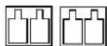
RX/TX TX 1 2 3 4
- Two-wireRS-485halfduplex
•Four-wireRS-485fullduplex - Two-wireRS-422simplex
- Four-wireRS-422fullduplexpointtopointcommunication
| FunctionPin Notes | ||
| RS-485/RS-422RX/TXA | 1 | (RX)ForfullduplexRS-485/RS-422(RX/TX)ForhalfduplexRS-485 |
| RS-485/RS-422RX/TXB | 2 | |
| RS-485/RS-422TXA | 3 | (TX)ForfullduplexRS-485/RS-422 |
| RS-485/RS-422TXB | 4 |
PerformanceConsiderations
When settings up your system, it is important to consider how various settings and situations will affect performance. Some factors affect the amount of bandwidth (the bit rate) required, others can affect the frame rate, and some affect both. If the load on the CPUreachesitsmaximum,thiswillalsoaffecttheframerate.
The following factors are among them most important to consider:
- High image resolution and/or lower compression levels result in images containing more data. Bandwidth affected.
TechnicalSpecifications
- AccessbylargenumbersofMotionJPEGand/orunicastH.264clients.Bandwidthaffected.
- Simultaneous viewing of different streams (resolution, compression) by different clients. Effect on frame rate and bandwidth.
- AccessingMotionJPEGandH.264videostreamssimultaneously.Framerateandbandwidthaffected.
- Heavyusageofeventsettingsaffecttheproduct'sCPUload.Framerateaffected.
• Heavy network utilization due to poor infrastructure. Bandwidth affected. - Viewing on poorly performing client computers lowers perceived performance. Frame rate affected.


- Liability
- IntellectualPropertyRights
- EquipmentModifications
- TrademarkAcknowledgments
- Support
- Electromagnetic Compatibility(EMC)
- Europe
- Australia/NewZealand
- Korea
- TableofContents
- HardwareOverview
- Connectors
- NOTICE
- Note
- AccessingtheProduct
- AccessfromaBrowser
- Accessfromthelnternet
- SettheRootPassword
- TheLiveViewPage
- ControlsontheLiveViewPage
- AXISMediaControlviewertoolbar
- AMCAudioControls
- PTZControls
- MediaStreams
- HowtoStreamH.264
- MJPEG
- AXISMediaControl(AMC)
- AlternativeMethodsofAccessingtheVideoStream
- AccessingAudioStreams
- SettingUptheProduct
- BasicSetup
- VideoandAudio
- VideoStream
- Image
- H.264
- Quadstream
- StreamProfiles
- CameraSettings
- ImageAppearance
- Videoinput
- ImageSettings
- PrivacyMask
- Overlay
- Toenableoverlays:
- OverlayImage
- AudioSettings
- AudioChannels
- Audiolnput
- AudioOutput
- AudioClips
- LiveViewConfig
- Defaultliveviewvideo
- DefaultViewerforBrowsers
- ViewerSettings
- UserDefined Links
- OutputButtons
- PTZ(PanTiltZoom)
- InstallingaPTZdriver
- PresetPositions
- GuardTour
- Advanced
- DeviceSettings
- Controls
- OSDMenu
- Applications
- Detectors
- CameraTampering
- MotionDetect ion
- AudioDetection
- Events
- SettingUpanActionRule
- Recipients
- Toaddarecipient:
- Schedules
- Tocreateanewschedule:
- Recurrences
- Tosetuparecurrence:
- Recordings
- RecordingList
- Continuousrecording
- SystemOptions
- Security
- Users
- ONVIF
- IPAddressFilter
- HTTPS
- IEEE802.1X
- AudioSupport
- Date& Time
- Network
- BasicTCP/IPSettings
- IPv4AddressConfiguration
- IPv6AddressConfiguration
- ARP/Ping
- AXISVideoHostingSystem(AVHS)
- AXISInternetDynamicDNSService
- AdvancedTCP/IPSettings
- DNSConfiguration
- NTPConfiguration
- HostNameConfiguration
- Link-LocalIPv4Address
- HTTP
- NATtraversal(portmapping)forIPv4
- FTP
- RTSP
- SOCKS
- QoS(QualityofService)
- SMTP(email)
- SNMP
- UPnPTM
- RTP/H.264
- Bonjour
- Storage
- SDCard
- NetworkShare
- Ports&Devices
- I/OPorts
- COMPort
- PortStatus
- Maintenance
- SupportOverview
- SystemOverview
- Logs&Reports
- Scripting
- FileUpload
- PlainConfig
- ResettoFactoryDefaultSettings
- Troubleshooting
- CheckingtheFirmware
- UpgradingtheFirmware
- EmergencyRecoveryProcedure
- Symptoms, Possible Causes and Remedial Actions
- TechnicalSpecifications
- Powerconnector
- Audioconnector
- RS-485/422connector
- PerformanceConsiderations
Brand : AXIS
Model : Q7424-R
Category : Server