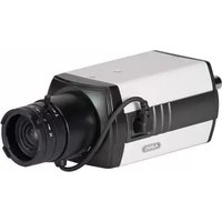
TVCC91500 - Surveillance Camera ABUS - Free user manual and instructions
Find the device manual for free TVCC91500 ABUS in PDF.


| Product type | Analog surveillance camera, Universal Analog Box 700 LTV |
| Brand / Model | ABUS TVCC91500 |
| Image sensor | 1/3" SONY SUPER HAD II CCD |
| Resolution | 700 TV lines |
| Pixels | 1028 (H) x 596 (V) total, 976 (H) x 582 (V) effective |
| Day/Night switching | Electromechanical IR filter, automatic or external |
| Minimum illumination | 0.1 Lux (color), 0.01 Lux (B/W), 0.0001 Lux (Slow-Shutter 256x) |
| Main functions | WDR, BLC, HLC, privacy masking (15 zones), digital zoom, image stabilizer (DIS), Defog function, motion detection, OSD |
| Video output | BNC, PAL |
| Power supply | 12 V DC ±10% or 24 V AC ±10%, max. 5 W (10 W with IR filter) |
| Dimensions (H x W x D) | 69 x 56 x 113.3 mm |
| Weight | 400 g |
| Operating temperature | -10 °C to 50 °C |
| Humidity | 90% max. |
| Maintenance and cleaning | Clean with a dry cloth, no chemicals. Do not open, no user-serviceable parts |
| Safety | Disconnect before installation, observe voltages, use surge protection, installation by qualified professional |
| Spare parts / Repairability | Lens not included. No user-repairable internal parts. Warranty void if opened |
| General information | Indoor use, requires outdoor housing for outdoor use. Compliant with European directives |
Frequently Asked Questions - TVCC91500 ABUS
User questions about TVCC91500 ABUS
0 question about this device. Answer the ones you know or ask your own.
Ask a new question about this device
Download the instructions for your Surveillance Camera in PDF format for free! Find your manual TVCC91500 - ABUS and take your electronic device back in hand. On this page are published all the documents necessary for the use of your device. TVCC91500 by ABUS.
USER MANUAL TVCC91500 ABUS
natural_image
Exterior view of a black and white ABBIS surveillance camera with visible lens and control panel (no text or symbols on body)natural_image
Exterior view of a black and white ABBIS 3.0 video camera with visible lens and control knobs (no text or symbols on body)Bedienungsanleitung
Version 07/2014
CE
natural_image
Technical line drawing of a mechanical component with cylindrical and rectangular features (no text or symbols)Universal Analog Box 700 TVL inkl. Montagematerial, exkl. Objektiv
Anleitung
natural_image
Technical line drawing of a mechanical device with no visible text or symbols5.2 Stromversorgung
natural_image
Exterior view of a black and white ABBIS 3.0 video camera with visible lens and control knobs (no text or symbols on body)User Guide
Version 07/2014
CE
English translation of the original German user guide. Retain for future reference.
Introduction
Dear customer,
Thank you for purchasing this product.
This device complies with the requirements of the applicable EU directives. The declaration of conformity can be obtained from:
To maintain this status and to guarantee safe operation, it is your obligation to observe the instructions in this user guide!
Read the entire user guide carefully before starting operation of the product, and pay attention to all operating instructions and safety information.
All company names and product descriptions are trademarks of the corresponding owner.
All rights reserved.
In the event of questions, please contact your local maintenance specialist or dealer.

Disclaimer
This user guide has been produced with the greatest of care. Should you discover any missing information or inaccuracies, please contact us in writing at the address shown on the back of the manual.
ABUS Security-Center GmbH & Co. KG assumes no liability for technical and typographical errors, and reserves the right to make changes to the product and operating instructions at any time and without prior notice.
ABUS Security-Center is not liable or responsible for direct or indirect damages resulting from the equipment, performance and use of this product. No forms of guarantee are accepted for the contents of this document.
Explanation of symbols
 | The triangular high voltage symbol is used to warn of the risk of injury or health hazards (e.g. caused by electric shock). |
 | The triangular warning symbol indicates important notes in this user guide which must be observed. |
 | This symbol indicates special tips and notes on the operation of the unit. |
Important safety information
 | All guarantee claims are invalid in the event of damage caused by non-compliance with this user guide. We cannot be held liable for resulting damage. |
 | In the event of material or personal damage caused by improper operation or non-compliance with the safety information, we cannot be held liable. All guarantee claims are void in such cases. |
The following safety information and hazard notes are not only intended to protect your health, but also to protect the device from damage. Please read the following points carefully:
- There are no components inside the product that require servicing. Dismantling the product invalidates the CE certification and the guarantee / warranty.
- The product may be damaged if it is dropped, even from a low height.
- Install the device so that the image sensor is not subjected to direct sunlight. Pay attention to the installation instructions in the corresponding section of this user guide.
- The device is designed for indoor use. For outdoor use, an appropriate outdoor housing must be used.
Avoid the following adverse conditions during operation:
- Moisture or excess humidity
• Extreme heat or cold - Direct sunlight
- Dust or flammable gases, vapours, or solvents
• Strong vibrations
• Strong magnetic fields (e.g. next to machines or loudspeakers) - The camera must not be installed on unstable surfaces
General safety information:
- Do not leave packaging material lying around. Plastic bags, sheeting, polystyrene packaging, etc., can pose a danger to children if played with.
- The surveillance camera contains small parts which could be swallowed, and should be kept out of reach of children for safety reasons.
- Do not insert any objects into the device through the openings.
- Only use replacement devices and accessories that are approved by the manufacturer. Do not connect any non-compatible products.
- Please pay attention to the safety information and user guides for the other connected devices.
- Check the device for damage before commissioning. Do not put the device into operation if you detect any damage.
- Adhere to the operating voltage limits specified in the technical data. Higher voltages could destroy the device and pose a health risk (electric shock).
Safety information
- Power supply: Observe the information on the nameplate regarding the supply voltage and power consumption.
- Overloading
Avoid overloading electrical sockets, extension cables, and adapters, as this can result in fires or electric shocks.
- Cleaning
Only use a damp cloth to clean the device. Do not use corrosive cleaning materials. Disconnect the device from the power supply while doing so.
Warnings
Observe all safety and operating instructions before putting the device into operation for the first time.
-
Observe the following information to avoid damage to the power cable and plug:
-
Do not pull the cable when disconnecting the device from the mains power – always take hold of the plug.
-
Ensure that the power cable is positioned as far away as possible from any heating equipment, as this could otherwise melt the plastic coating.
-
Follow these instructions. Non-compliance with these instructions could lead to an electric shock.
-
Never open the housing or power supply unit.
- Do not insert any metallic or flammable objects into the device.
-
Use overvoltage protection to prevent damage caused by overvoltage (e.g. electrical storms).
-
Disconnect defective devices from the power immediately and contact your specialist dealer.
 | When installing the device in an existing video surveillance system, ensure that all devices have been disconnected from the power supply and low-voltage circuit. |
 | If in doubt, have a specialist technician carry out assembly, installation, and connection of the device. Improper or unprofessional work on the power supply or domestic installation puts both you and other persons at risk.Connect the installations so that the power supply circuit and low-voltage circuit always run separately from each other. They should not be connected at any point or be able to become connected as a result of a malfunction. |
Unpacking the device
Handle the device with extreme care when unpacking it.
| If the original packaging has been damaged, inspect the device. If the device shows signs of damage, return it in the original packaging and inform the delivery service. |
Contents
- Intended use 27
- Scope of delivery....27
- Features and functions....27
- Camera description....28
- Mounting / installation .... 30
5.1 Mounting the camera 30
5.2 Power supply....30
5.3 Installing the video cable....30 - OSD menu 31
- Maintenance and cleaning 38
7.1 Maintenance....38
7.2 Cleaning....38 - Disposal 38
- Technical data....39
1. Intended use
The Universal analogue box 700 TVL is suitable for use during the day and at night. The Universal analogue box 700 TVL is equipped with a high-quality image sensor. It is used for video surveillance in conjunction with a recording device or surveillance monitor. The device is designed for indoor use. For outdoor use, an appropriate outdoor housing must be used.
2. Scope of delivery

natural_image
Technical line drawing of a mechanical component with cylindrical and hexagonal sections (no text or symbols)Universal analogue box 700 TVL Includes mounting material, does not include lens
Manual
3. Features and functions
• Universal analogue box 700 TVL
• Detailed high resolution thanks to 700 TVL
• WDR function to compensate for high image contrasts
• Privacy masking function
- On-screen display for convenient setting of camera parameters
- Camera description
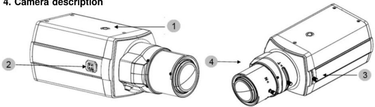
| 1 | Fastening base for camera mount |
| 2 | Lens connection (auto-iris interface) |
| 3 | Back-focus setting |
| 4 | Lens (not supplied) |
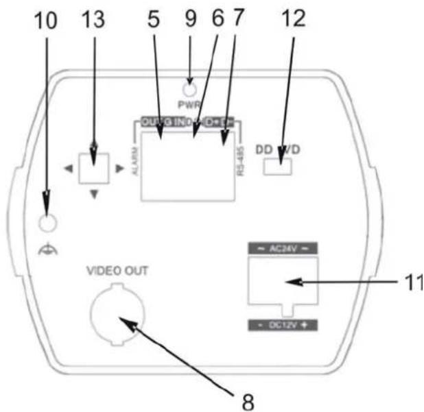
| 5 | Switching input (jumper to earth), switching output(open collector, 5 V DC, max. 200 mA), earth connection |
| 6 | Day/night switching |
| 7 | RS485 interface |
| 8 | Video output |
| 9 | Status LED (active when power is on) |
| 10 | Earth |
| 11 | 12 V DC / 24 V AC power connection |
| 12 | DD/VD lens type switching |
| 13 | OSD menu buttons |
| Connection Description Maximum load | |||
| OUT: Alarm output | The alarm output is switched either by the integrated motion detector or by the alarm input.The alarm output is a transistor output (open collector) with a maximum load of 200 mA switching current. The output is designed purely as a switching output. An external power supply is required when it is used. | 200 mA |  |
| G: Ground Earth connection | |||
| IN: Alarm input | The digital input is activated by connecting the IN and G connections. | ||
| D/N Connection | for a light-dependent resistor (LDR) to control the day/night function. | ||
5. Mounting / installation
5.1 Mounting the camera
| NOTEThe camera must be disconnected from the mains power during installation. |
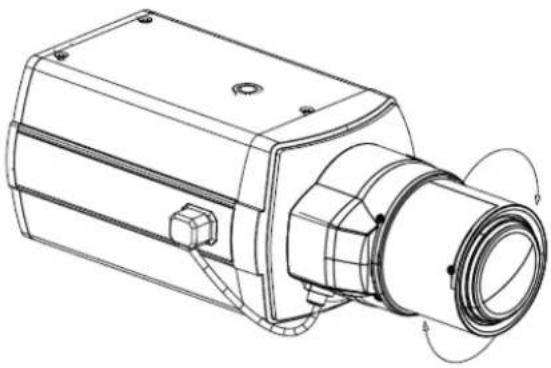
There are 1/4 inch screw sockets on the top and bottom of the camera for installing a suitable camera mount.
natural_image
Technical line drawing of a mechanical device with no visible text or symbols5.2 Power supply
 | NOTEBefore starting installation, make sure the supply voltage is the same as the rated voltage of the camera. | |
 | (1) 12 V DC / 24 V AC | |
The cameras require a 12 V DC or 24 V AC power supply. The polarity of the DC power supply is not important.
5.3 Installing the video cable
In order to transmit the video signal to a converter, monitor, or recorder, a coaxial cable of type RG59 with BNC plug (male) must be connected to the "Video OUT" connection. The cable length to the next device may not exceed 150 meters. Suitable signal amplifiers can be installed to increase the range.
6. OSD menu
Press the OSD menu control button to open the OSD menu. You can make detailed settings in this on-screen menu.
SETUP MENU
PAGE 1 / 2
SCENE SELECT CUSTOM
PICT ADJUST ↓
EZOOM OFF
DIS OFF
PRIVACY MASK ↓
MOTION DET OFF
SYS SETTINGS ↓
EXIT
SETUP MENU
PAGE 2 / 2
LANGUAGE ENGLISH
VERSION 1.0
MAINTENANCE ↓
| Page 1 / 2 | |
| Function Description | |
| SCENE SELECT The camera | has various presets for different ambient conditions. |
| CUSTOM: All sub-functions can be manually adjusted for the environment. | |
| FULL AUTO: This mode can be used for various scenes. It is not designed for any particular ambient conditions. | |
| INDOOR: This mode is designed for indoor applications. | |
| OUTDOOR: This mode is designed for outdoor applications. | |
| BACKLIGHT: This mode is used for scenes with indoor and outdoor light, for example in entrance areas indoors with a view outside. | |
| ITS: This mode is specially designed for moving objects. | |
| PICT ADJUST | Settings for picture parameters such as brightness and contrast |
| EZOOM | Digital zoom settings |
| DIS | Settings for the digital image stabilisation function |
| PRIVACY MASK | Settings for privacy masking |
| MOTION DET | Settings for motion detection |
| SYS SETTINGS General system settings | |
| EXIT | Quit the camera menu |
| Page 2 / 2 | |
| Function Description | |
| LANGUAGE | Shows the language of the OSD (on-screen display). |
| VERSION | Shows the currently installed firmware version. |
| MAINTENANCE | Resets all camera parameters to the default settings. |
SCENE SELECT
The following setting options are described for the "CUSTOM" option. This option contains all the functions in the SCENE SELECT submenu.
For the other options (FULL AUTO, INDOOR, OUTDOOR, BACKLIGHT, ITS), sub-functions are either enabled or disabled by default.
| ADVANCEC MENU | |
| PAGE 1 / 2 | |
| SHUTTER/AGC | AUTO↓ |
| WHITE BAL | ATW↓ |
| HLC/BLC | OFF |
| WDR/ATR-EX | WDR↓ |
| DNR | ↓ |
| DAY/NIGHT | AUTO↓ |
| IR OPTIMIZER | OFF |
| RETURN | |
| ADVANCED MENU | |
| PAGE 2 / 2 | |
| LENS SHD COMP OFF | |
| DEFOG | OFF |
| FLK LESS OFF | |
| ANTI CR OFF | |
| RETURN | |
| Page 1 / 2 | |
| Function Description | |
| SHUTTER/AGC These settings control the exposure of the camera images. | |
| AUTO:AE LEVEL (1-250): Setting for target automatic exposure value (basic brightness).AGC MAX (6-44.8 dB): Setting for maximum gain valueSENSE UP (OFF, AUTO): AUTO: Automatic extension of exposure time for a brighter pictureOFF: Function inactive | |
| MANUAL: Manual exposure time settingSHUTTER (x256-x2, 1/50-1/10000): Exposure time settingAGC MAX (6-44.8 dB): Setting for maximum gain value | |
| FIX: Fix exposure time at current point in time | |
| WHITE BAL | This function executes white balance for a realistic colour image. |
| ATW: Auto tracking white balance – automatic regulation from 1800-10500 K.SPEED (0-255): Control speedDELAY CNT (1-255): Delay before controlATW FRAME (1-255): Calculation intervalENVIRONMENT (INDOOR, SUNNY, SHADE, AUTO): Preset for adapting to ambient light | |
| PUSH: Continuous white balance without restriction of colour temperature. Very intensive colours in the video image can affect the result. | |
| USER1/2: Manual, user-defined setting of the blue and red values.Two different sets can be set up.B-GAIN (0-255): Blue gain valueR-GAIN (0-255): Red gain value | |
| MANUAL: Sets the white balance based on the black body curve, adjustable in 64 steps.LEVEL (0-63): Level setting in 64 steps | |
| PUSH LOCK: Executes the white balance as PUSH and uses these values constantly. | ||
| HLC/BLC | OFF: Function deactivatedHLC: Highlight compensation – an area is marked black above a certain brightness. This means edges around objects are much clearer.BLC: Backlight compensation – dark areas are brightened while attempting to maintain the brightness of light areas. | |
| WDR/ATR-EX Functions for compensating for high contrast | ||
| OFF: Function deactivatedATR-EX: Software calculation of the WDR functionCONTRAST (LOW, MID, HIGH): Contrast settingL O W : L oMID: MediumH I G H : HCLEAR FACE (OFF, LOW, MID, HIGH):Gain function for high-frequencys e c t i o nWDR: WDR function with double image exposureCONTRAST (LOW, MID, HIGH): Contrast settingL O W : L oMID: MediumH I G H : HCLEAR FACE (OFF, LOW, MID, HIGH):Gain function for high-frequencys e c t i o n | ||
| DNR Function to reduce image noiseLEVEL (0-6): The higher the value, the less image noise. | ||
| DAY/NIGHT Settings for day/night switching. | ||
| IR OPTIMIZER | Function to improve the image quality in night mode when using external IR floodlightsOFF: Function deactivatedON: Function activatedMODE (AUTO, CENTER): Reference area for calculation | |
| AUTO: AutomaticCENTER: Middle areaIR AREA: TOP (0-6): Upper edge of areaBOTTOM (0-6): Lower edge of areaLEFT (0-8): Left limitRIGHT (0-8): Right limitWEIGHT (0-15): WeightingLEVEL (0-12): Degree of improvement The higher the value, the more the camera tries to improve the imageIR LED:OFF: OffFIX: Fixed intensity levelLEVEL (0-255): Level selectionDAY/NIGHT: Reference for IR light intensity is the auto exposure settingLEVEL MIN (1-255): Minimum intensityLEVEL MAX (1-255): Maximum intensityCOLOR NIGHT: Colour display in night modeOFF: Function deactivatedON: Function activatedCOLOR GAIN (LOW, MID, HIGH): Colour gainL O W : L MID: Medium H I G H :IR SHADE COMP: Compensation for irregular IR illumination in the video image (corners are darker than the middle of the image)OFF: Function deactivatedON: Function activatedPATTERN (SET1, SET2, SET3): Illumination pattern selectionPOSH (0-959): Horizontal positionPOSV (0-578): Vertical positionLEVEL (OFF, LOW, MID, HIGH):Function levels: Off, Low, Medium, High | ||
| RETURN Back to the previous menu page | ||
| Page 2 / 2 | |
| Function | Description |
| LENS SHD COMP | Compensation for irregular IR illumination in the video image (corners are darker than the middle of the image)OFF: Function deactivatedON: Function activated |
| DEFOG | Function to reduce for effects in the video imageOFF: Function deactivatedON: Function activatedLEVEL (LOW, MID, HIGH): Function levels Low, Medium, High |
| FLK LESS | Function to prevent flickerOFF: Function deactivatedON: Function activatedMODE: GAIN CTRL:SHUTTER FIX: Fixed exposure time |
| ANTI CR Function to prevent colour roll effects in the imageOFF: Function deactivatedON: Function activatedAUTO: Automatic activation of the function |
| RETURN Back to the previous menu page |
PICT ADJUST
| Function Description | |
| BRIGHTNESS (0-255): Image brightness setting | |
| CONTRAST (0-255): Image contrast setting | |
| SHARPNESS (0-255): Image sharpness setting | |
| HUE | (0-255): Hue setting |
| COLOR GAIN (0-255): Saturation setting | |
| RETURN Back to the previous menu page | |
EZOOM
| Function Description | |
| EZOOM Digital zoom function | OFF: Function deactivatedON: Function activatedMAG: Zoom factorPAN: Horizontal position of zoom areaTILT: Vertical position of zoom area |
| RETURN Back to the previous menu page | |
DIS
| Function Description | |
| DIS Digital image stabiliser: | The digital image stabiliser detects recurring movements of the camera (such as movement of the camera housing caused by the wind) and attempts to stabilise the image. |
| OFF: Function deactivatedON: Function activated | |
| RETURN Back to the previous menu page | |
PRIVACY MASK
| Function Description | |
| Privacy mask Function for masking areas of the video image | |
| AREA SEL | (0-15): Selection of areas for configuration |
| DISPLAY OFF: Deactivates | the selected areaON: Activates the selected area |
| POSITION | Sets the position of the area. Press the OSD directional pad to select the next corner of the area. |
| COLOR | (RED, GREEN, BLUE, YELLOW, CYAN, MAGENTA, WHITE, BLACK):Selection of the colour for the area |
| TRANSP | (0-1.0) Setting for the transparency of the area |
| MOSAIC | OFF: Mosaic view of the area deactivatedON: Mosaic view of the area activated |
| RETURN Back to the previous menu page | |
MOTION DET
| Function Description | |
| MOTION DET Settings for the | motion detection function. The alarm output is activated when a change in the image is detected.OFF Function deactivatedON: Function activated |
| DETECT SENSE (0-127): Sensitivity setting for motion detection | |
| INTERVAL (0-127): Detection interval. A higher value increases the time until the next detectable event | |
| BLOCK DISP OFF: Live display of image changes deactivatedON: Live display of image changes activated (block view of the detected area) | |
| MASK AREA (1-96): A blue marking means the motion detection area is activated. | |
| MONITOR AREA | AREA SEL (1-4): Selection of the motion area for configurationAREA MODE (OFF, ON):OFF: Motion area deactivatedON: Motion area activatedTOP (0-15): Setting for the upper limit of the areaBOTTOM (0-15): Setting for the lower limit of the areaLEFT (0-15): Setting for the left limit of the areaRIGHT (0-15): Setting for the right limit of the area |
| RETURN Back to the previous menu page | |
SYS MODE
| Function Description | |
| SYNC MODE | Image synchronisation settingsINT: Internal synchronisationLL: When using a 24 V AC power supply, LINE LOCK (LL) can be used. |
| LENS | AUTO: Automatic detection of lens typeTYPE (DC, VIDEO): Manual selection between voltage-controlled (DC) or video signal-controlled lens typeMODE (AUTO, OPEN, CLOSE): Iris settingAUTO: Automatic modeOPEN: Iris fully openCLOSE: Iris closedADJUST: Auto iris calibrationSPEED (0-255): Iris control speedMANUAL: Manual iris setting |
| FLIP | Image mirroring functionOFF: Function deactivatedV: Vertical image mirroringH: Horizontal image mirroringHV: Horizontal and vertical image mirroring |
| LCD/CRT Adjusts gamma value to the video display unitLCD: Preset for LCD monitorsCRT: Preset for CRT monitors |
| COMMUNICATION Settingsfor the RS485 interface of the cameraPROTOCOL (PELCO-D): Protocol information (Pelco-D only)ADDRESS (1-255): Bus address (bus ID)BAUDRATE (2400-115200): Baud rate settingDATABIT (8 BIT): Data bit setting (8 bit only)PARITY (OFF, ODD, EVEN): Parity settingSTOPBIT (1 BIT): Stop bit setting (1 bit only) |
| CAMERA ID OFF: Cameraname not shown in video imageON: Camera name shown in video imageAvailable characters: Letters, numerals, signs, symbols (CHR1, CHR2)Up, Down, Right, Left: Change selection and skip to 2nd lineCLR: Delete highlighted characterPOS: Change position |
| RETURN Back to the previous menu page |
LANGUAGE
| Function Description | |
| LANGUAGE (ENGLISH): The language of the screen menu is fixes as English. | |
| RETURN Back to the previous menu page | |
VERSION
| Function Description | |
| VERSION (1.0): Currently installed firmware version of the camera | |
| RETURN Back to the previous menu page | |
MAINTENANCE
| Function Description | |
| CAMERA RESET Select this function to reset the camera to the factory settings. | |
| RETURN Back to the previous menu page | |
7. Maintenance and cleaning
7.1 Maintenance
Examine the technical safety of the product regularly, e.g. check the housing for damage.
If it seems that it may no longer be possible to operate the device safely, stop using the product and protect it from unintentional use.
It is likely that safe operation is no longer possible in the event that:
- The device shows signs of visible damage.
- The device no longer works correctly.

Please note:
You do not need to perform any maintenance on the product. There are no components to service and nothing inside the product to check. Never open it.
7.2 Cleaning
Clean the device with a clean, dry cloth. The cloth can be dampened with lukewarm water if the dirt on the monitor is hard to remove.

Do not allow any liquids to enter the device.
Do not use any chemical cleaning products, as they could damage the surface of the housing and screen (discoloration).
8. Disposal

Note: EU Directive 2002/96/EC regulates the proper return, treatment and recycling of used electronic devices. This symbol means that in the interest of environmental protection the device must be disposed of separately from household or industrial waste at the end of its service life in accordance with applicable local legal guidelines. Used devices can be disposed of at official recycling centres in your country. Obey local regulations when disposing of material. Further details on returns (also for non-European countries) can be obtained from your local authority. Separate collection and recycling conserves natural resources and ensures that all the provisions for protecting health and the environment are observed when recycling the product.
9. Technical data
| Model number TVCC91500 | |
| Image sensor 1/3" SONY SUPER HAD II CCD | |
| DSP | Sony |
| Camera type Universal analogue box 700 TVL | |
| Resolution | 700 |
| Pixels (total) 1028 (H) x 596 (V) | |
| Pixels (effective) 976 (H) x 582 (V) | |
| Day/night switching Electromechanical IR cut filter | |
| Minimum illumination (colour) 0.1 Lux | |
| Minimum illumination (B/W) 0.01 Lux (slow shutter off) / 0.0001 Lux (slow shutter 256x) | |
| Noise reduction 3D digital noise reduction | |
| Electronic shutter control PAL: 1/50 s to 1/10,000 s | |
| Backlight compensation WDR / BLC / HLC | |
| Privacy masking | 15 zones |
| Digital zoom | Yes |
| Image functions | DIS (digital image stabiliser) / defog function |
| Video system | PAL |
| Connections | Video signal (BNC), power supply (DC), RS485 |
| Power supply | 12 V DC ± 10%, 24 V AC ± 10% |
| Power consumption | Max. 5 W (max. 10 W with IR filter activated) |
| Operating temperature | -10 °C - +50 °C |
| Humidity | Max. 90% |
| Dimensions (Hx∅) | 69 x 56 x 113.3 mm |
| Weight | 400 g |
TVCC91500

natural_image
Exterior view of a black and white ABBIS 3.0 camera with visible lens and control knobs (no text or symbols on body)natural_image
Technical line drawing of a mechanical component with cylindrical and rectangular features (no text or symbols)natural_image
Technical line drawing of a mechanical device with no visible text or symbolsnatural_image
Exterior view of a black and white ABBIS 3.0 video camera with visible lens and control knobs (no text or symbols on body)natural_image
Technical line drawing of a mechanical component with cylindrical and rectangular features (no text or symbols)natural_image
Technical line drawing of a mechanical device with no visible text or symbolsnatural_image
Exterior view of a black and white ABBIS 3.0 video camera with visible lens and control knobs (no text or symbols on body)natural_image
Technical line drawing of a mechanical component with cylindrical and hexagonal sections (no text or symbols)Universal analog boks 700 TVL inkl. monteringsmateriale, ekskl. objektiv

Vejledning
natural_image
Technical line drawing of a mechanical device with no visible text or symbols5.2 Strømforsyning
natural_image
Exterior view of a black and white ABBIS 3.0 video camera with lens and control panel (no text or symbols on body)Instrukcja obsługi
Wersja 07/2014
CE
natural_image
Technical line drawing of a mechanical component with cylindrical and rectangular features (no text or symbols)natural_image
Technical line drawing of a mechanical device with no visible text or symbolsnatural_image
Exterior view of a black and white ABBIS 3.0 video camera with visible lens and control knobs (no text or symbols on body)natural_image
Technical line drawing of a mechanical component with cylindrical and rectangular features (no text or symbols)natural_image
Technical line drawing of a mechanical device with no visible text or symbols5.2 Электропитание
- Bedienungsanleitung
- Stromversorgung
- User Guide
- Introduction
- Disclaimer
- Explanation of symbols
- Important safety information
- The following safety information and hazard notes are not only intended to protect your health, but also to protect the device from damage. Please read the following points carefully:
- Safety information
- Warnings
- Unpacking the device
- Contents
- Intended use
- Scope of delivery
- Features and functions
- Mounting / installation
- Mounting the camera
- Power supply
- Installing the video cable
- OSD menu
- SCENE SELECT
- LANGUAGE
- VERSION
- MAINTENANCE
- Maintenance and cleaning
- Maintenance
- Please note:
- Cleaning
- Disposal
- Technical data
- TVCC91500
- Strømforsyning
- Instrukcja obsługi
- Электропитание
Brand : ABUS
Model : TVCC91500
Category : Surveillance Camera