
TA 211 E - Thermostat BOSCH - Free user manual and instructions
Find the device manual for free TA 211 E BOSCH in PDF.


| Product type | Atmospheric influence inlet temperature thermostat |
| Brand | Bosch |
| Model | TA 211 E |
| Category | Thermostat |
| Power supply | 24 V DC (measuring current) |
| Outdoor sensor measuring range | -20 ... +30 °C |
| Permissible ambient temperature for outdoor sensor | -30 ... +50 °C |
| Protection class | III |
| Main functions | Heating curve control (curve foot 10-60 °C, max inlet temperature 40-90 °C), night setback (0 to -40 K), automatic/reduced/frost protection mode switching, shutdown limit (15-25 °C) |
| Compatible accessories | Timer switch (EU 3 T, DT 1, EU 2 D, DT 2), remote control (TW 2, TFQ 2 T, TFQ 2 W, TFP 3), mechanical temperature limiter for underfloor heating |
| Outdoor sensor included | Yes (AF sensor, mounting on northeast to northwest façade, 2 m above ground) |
| Recommended cable cross-section (outdoor sensor) | 0.75-1.5 mm² up to 20 m, 1.0-1.5 mm² up to 30 m, 1.5 mm² beyond |
| Compatibility | Bosch gas heating appliances with Bosch Heatronic |
| Safety | Do not connect to 230 V; follow connection diagram; disconnect power before installation |
| Protection rating | CE |
| Maintenance | No specific cleaning required; avoid dust accumulation on contacts |
| Spare parts and repairability | AF outdoor sensor available; in case of failure, error codes AC or CC displayed on the heating appliance |
| General information | Thermostat mounted in the switching box of the heating appliance; works only with timer switch according to German regulations |
Frequently Asked Questions - TA 211 E BOSCH
User questions about TA 211 E BOSCH
0 question about this device. Answer the ones you know or ask your own.
Ask a new question about this device
Download the instructions for your Thermostat in PDF format for free! Find your manual TA 211 E - BOSCH and take your electronic device back in hand. On this page are published all the documents necessary for the use of your device. TA 211 E by BOSCH.
USER MANUAL TA 211 E BOSCH
6 720 610 281 (00.08) OSW
4100-00.3/G
Deutsch
Correct functioning is ensured only when these instructions are observed. We request that this booklet be given to the customer.
Français
natural_image
Line drawing of an open book with blank pages (no text or symbols)1

2

natural_image
Technical line drawing of an electronic device with connectors and screw packages (no text or symbols)
4

line
| AT | VT | | --- | --- | | 0 | 30 | | 15 | 40 | | 30 | 50 | | 45 | 60 | | 60 | 70 | | 75 | 80 | | 90 | 90 |Inhaltsverzeichnis
Sparautomatik
1 Safety Notes 10
2 Application 10
3 Technical Data 10
4 Mounting 11
5 Electrical Connection 11
6 Placing into Operation 12
7 Operation of the Regulator 12
8 Programming the time switch 15
9 General Notes 15
10 Malfunction 15
1 Safety Notes
The regulator is installed into the boiler facia. The regulator may only be connected according to the wiring diagram. Under no circumstances should the regulator be connected to the 230 V mains.
The regulator is to be used exclusively in connection with a boiler equipped with Bosch Heatronic control.
Before installing the regulator, the voltage supply (230 V, 50 Hz) to the boiler must be disconnected.
2 Application
TA 211 E is a flow temperature regulator controlled by outside temperature to be installed into the facia of appliances, equipped with Bosch Heatronic control.
2.1 Items Supplied
Included in the items supplied (Fig. 2 with the TA 211 E is an outside temperature sensor with mounting material.
2.2 Accessories
A mechanical flow temperature limiter must be fitted to the flow pipe of underfloor heating systems, in accordance with the manufacturer's instructions.
The TA 211 E is supplied without a time switch. This is available as an accessory.
A remote control with a time switch can also be used (not in UK, see the following table)
The following combinations are permisable:
| Combination | Electrical cuit Diagram |
| TA 211 E + EU 3 T | Fig. 8 |
| TA 211 E + DT 1 | Fig. 8 |
| TA 211 E + EU 2 D | Fig. 8 |
| TA 211 E + DT 2 | Fig. 8 |
| TA 211 E + EU 3 T + TW 2 | Fig. 9 |
| TA 211 E + DT 1 + TW 2 | Fig. 9 |
| TA 211 E + EU 2 D + TW 2 | Fig. 9 |
| TA 211 E + DT 2 + TW 2 | Fig. 9 |
| TA 211 E + TFQ 2 T | Fig. 10 |
| TA 211 E + TFQ 2 W | Fig. 10 |
| TA 211 E + TFP 3 | Fig. 10 |
* Not in UK.
Note: According to Par. 7 of the Heating System Regulations, the TA 211 E can be operated only in conjunction with a time switch.
3 Technical Data
| Measuring range of the outside temperature sensor | -20...+30°C |
| Permissible ambient temperature of the outside temperature sensor - 30 ... | +50°C |
| Protection class III | |
| CE |
3.1 Measured Values, Outside Temperature Sensor AF
| °C Ω | AF | V | °C | Ω AF | V |
| -20 | 2392 | 2.64 | 4 | 984 | 1.65 |
| -16 | 2088 | 2.49 | 8 | 842 | 1.49 |
| -12 | 1811 | 2.33 | 12 | 720 | 1.34 |
| -8 | 1562 | 2.16 | 16 | 616 | 1.20 |
| -4 | 1342 | 1.99 | 20 | 528 | 1.07 |
| 0 | 1149 | 1.82 | 24 | 454 | 0.95 |
4 Mounting

Before starting work, the voltage supply (230 V, 50 Hz) to the boiler must be disconnected.
4.1 Mounting of the Outdoor Temperature Sensor AF (Figures 3 and )5
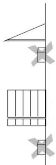
The outside temperature sensor AF is intended for mounting on the surface of an outer wall.
The following aspects should be observed:
- Between the Northeast and Northwest sides of the house
• A minimum of 2 m over ground level - It should not be influenced by windows, doors, chimneys, direct sunlight or similar effects (Fig. 5)
- In recesses or under balcony and roof overhangs are not suitable as mounting locations (Fig. 5)
- If the major occupied rooms of the building are all located in the same direction, the outdoor sensor can point in that direction.
Notes:
- If the outdoor sensor is mounted on an east wall, the sensor must be shadowed in the early morning hours (e. g., by a neighbouring house of a balcony).
Reason: The morning sun disturbs the heating up of the house after the end of the reduced night program. - If the major occupied rooms point in two adjacent directions, mount the outdoor sensor on the side of the house that has the worst climatic conditions.
- For the mounting height, the (vertical) centre of the height heated by the boiler has proven to the most suitable (H/2 in Fig. 5)
To mount, remove the cover ( AF_c with AF_b ) and attach the sensor housing ( AF_a ) with two screws to the outer wall (Fig. 3)
Legend for Figure 5
Y/H = Occupied height to be controlled by the sensor.
■ = Recommended mounting location
☐ = Alternative mounting location
4.2 Mounting the Regulator (Figures 11 and 15)
① Pull out the cover (f) at the bottom and remove (Fig. 11)
② Unscrew the screw (g, Fig. 12).
③ Remove the cover (h) forwards.
④ Pull the blank panel (i) downward and remove (Fig. 13)
⑤ Insert the TA 211 E from below into the guide rails and slide up until it clicks (Fig. 14).
⑥ Insert the plug (k) attached to the regulator into the intended connector (Fig. 15)
4.3 Mounting the Accessories
Mount the time switch, and the mechanical limiter in accordance with the associated installation instructions.
5 Electrical Connection
The electrical connection of the regulator has already been described in Section 4.2.
The following conductor cross sections are to be used:
• From TA 211 E to the outdoor sensor:
Length to 20 m 0.75 mm ^2 to 1.5 mm ^2
Length to 30 m 1.0 mm ^2 to 1.5 mm ^2
Length over 30 m 1.5 mm ^2
• From TA 211 E to the remote control
(not in UK): 1.5 mm ^2
Taking the applicable regulations into consideration, the electrical cable used for the connection of the outdoor sensor and the remote control must be at least type H 05 VV-...
All 24 V lines (measurement current) must be laid separately from lines carrying 230 V or 400 V so that no inductive effects take place (Minimum distance 100 mm).
If external inductive influences such as those caused by power cables, tram lines, transformer stations, radio and television equipment, amateur radio stations, microwave equipment or similar are to be expected, shielded cable should used for the signal lines.
With the installation of the TA 211 E Regulator, the electronics of the heating unit automatically use the pump switching type III (continuous pump operation), also when the factory setting was not changed!
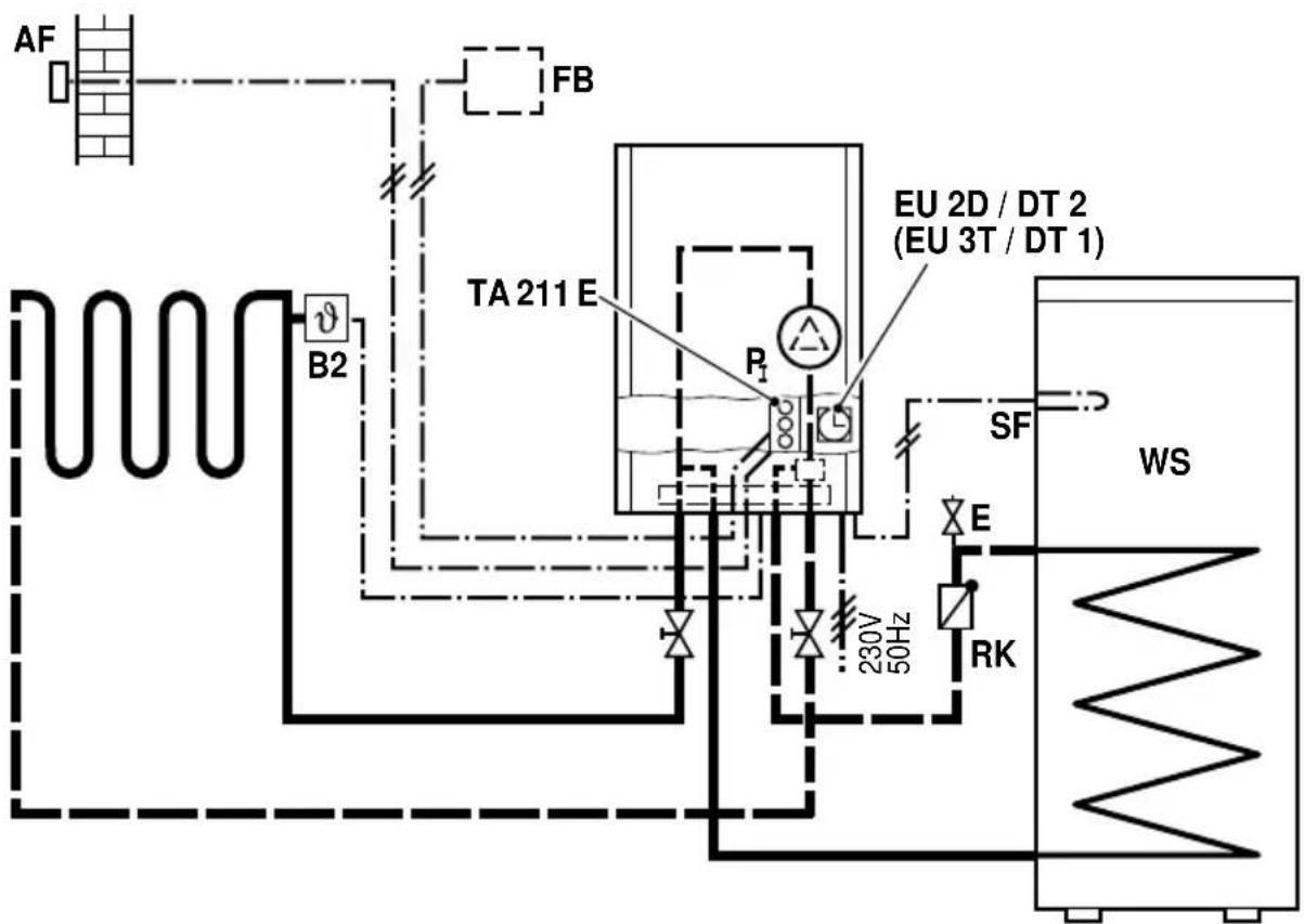
The figures 6 and 7 re schematics of the application of the TA 211 E with radiator and floor heating systems.
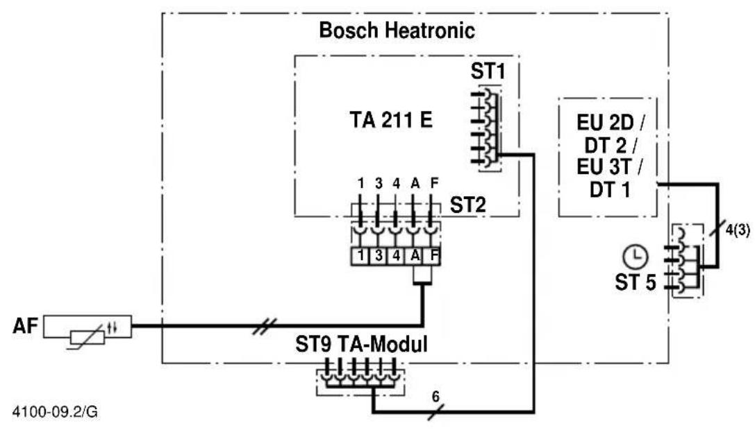
The corresponding electrical connection diagram (Figure 8o)10 to be used.
Legend for the Figures 6o 10:
P_I Circulation pump
SF Storage temperature sensor (NTC)
B_2 Mechanical flow temperature limiter (only in connection with underfloor heating systems)
AF Outside temperature sensor
WS Warm water storage
RK Check valve
E Venting valve
5.1 Electrical Connection of the Outside Temperature Sensor (AF)
- Remove the cover (AF _c with AF _b , Fig. 3)
- Insert the cable through the threaded fitting (AF) and connect to the two terminals (AF _e ).
- Tighten the threaded fitting (AF _d ) so that strain relief and splash water protection is provided at the cable feed-through.
- Close the outside sensor.
- On the boiler, insert the cable through the protective sleeve and secure with the strain relief.
- Connect the cable to the TA 211 E on the terminals "A" and "F" (Figure 8o)10
5.2 Electrical Connection of Accessories (Figure 8 10)
5.2.1 Time Switch
- Connect the time switch (if available) according to Figure 8 on the main circuit board of the boiler to connector ST 5
5.2.2 Remote Control (not in UK)
- Connect the TW 2 Remote Control (in case available) on the TA 211 E to the terminals 3 and 4 (Fig. 9)
- Connect the TFQ 2 T, TFQ 2 W or TFP 3 Remote Controls (in case available) to the terminals 1, 3 and 4 (Fig. 10)
5.2.3 Mechanical Flow Temperature Limiter
- An additional mechanical flow temperature limiter is to be connected to the feed of floor heating systems. The electrical connection is to be made according to the installation instructions of the heating unit.
5.3 Closing the Switching Box
- Replace the cover (h) and screw in the screw (g, Fig. 12).
- Snap in the cover (f, Fig. 11).
6 Placing into Operation
By operating the boiler, the TA 211 E Regulator is also activated.
7 Operation of the Regulator
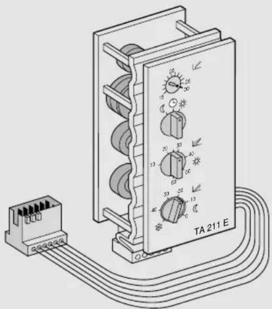
Legend for the Figures 1 and :4
a_I Outside temperature for boiler switching off point
b Operating Mode Switch
c Base point
d Night Reduction
e Maximum flow temperature
VT Flow temperature
AT Outside temperature
MVT Average feed temperature
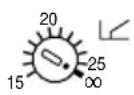
7.1 Outside temperature for boiler switching off point (a)
With this adjustment knob, the outdoor temperature (15 to 25 °C) can be set at which the appliance is automatically switched off or on.
Example: In the position “20”, the appliance is switched off at outdoor temperatures over approx. +20.5 °C and automatically switched on again at temperatures under approx. +18.5 °C.
The set value is determined by the user. In the position set at the factory, this function is not active and makes heating operations possible at any outside temperature, e. g., the operation of the system in midsummer.
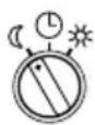
7.2 Operating Mode Switch (b)
With this switch, selection can be made between the following three operating modes:

7.2.1 Continuous Reduced Operation
In combination with the setting function for night reduction (d), the following behaviour results:

Continuous off with frost protection function
For outside temperatures over +4 °C, the appliance is off. For outside temperatures under +3 °C, the appliance is regulated to the minimum temperature. The circulation pump runs.
Attention: Care should be taken during the frost protection function that the feed temperature selector on the heating unit is set to at least "1" or "▶".
Select this position in summer and during winter vacations when the room temperature can be significantly reduced (Caution: House plants, pets).
In this case, the normal operation setting on the time switch (accessory) is ignored. Switch back again later to the automatic switching mode ⏻.
Reduced operation in combination with a value of between "0" and "-40" for the night reduction (d) results in the following function:
+

Continuous reduced operation
The flow temperature is continuously reduced by the value set on the adjustment knob (d). This operating mode provides reduced heating operation with the circulation pump running.
^1p Select this position during winter vacations when the room temperature cannot be significantly reduced.
In this case, the normal operation setting on the time switch (accessory) is ignored. Switch back again later to the automatic switching mode ⏻.
During reduced operation, the appliance remains in operation with reduced temperature regardless of outdoor temperature and the pump runs.

7.2.2 Timed Switching
Between normal and reduced operating according to the time switch settings.
In combination with the setting for night reduction (d), the following function results:

+

Timed economy heating
Timed switching between normal and frost protection operation according to the time switch programming.
During frost protection operation (e. g., at night), the burner and pump are switched off for outside temperatures over approx. +3 °C.
Attention: Care should be taken during the frost protection function that the feed temperature selector on the heating unit is set to at least "1" or "▶".
Tip 3 Select this economy position when the thermal insulation in your building is good and prevents rapid cooling.
+ -30 -20 Timed se back Operation
Automatic switching between normal and reduced operation according to the time switch program.
Select this position when the thermal insulation in your building is not so good and reduced heating operation is necessary (e.g., at night) to prevent considerable cooling. During reduced operation, the appliance remains in operation with reduced temperature for any outdoor temperature and the pump runs.

7.2.3 Continuous Normal Operation
The flow temperature is not reduced.
Select this setting when you will be staying up late as an exception (e.g., party). In this case, the setting on the time switch (accessory) for reduced operation is ignored. Do not forget to switch back again later to automatic switching operation
7.3 Setting the Heating Curve
The heating curve determines the flow temperature to which the appliance is limited, based on the measured outside temperature. With a correctly set heating curve, a constant room temperature is maintained for any outdoor temperature.
The heating curve (Fig. 4 of the TA 211 E results from a base point (c) and the maximum feed temperature (e).
When commissioning, set flow temperature control so that the dot is pointing to the right (Fig. 1, e).

7.3.1 Base Point Adjustment (c)
The base point of the heating curve sets the flow temperature (radiator temperature) in ^ C when the outside temperature is +20 ^ C. It can be set to values between 10 and 60 ( ^ C).
The heating curve shown in Fig. 4 is for a base point of 25 °C. This setting of the base point should be selected as a first starting point.
In case your heating equipment permits, select a lower setting value (e. g. 20). In case the room temperature is too low with fully opened thermostat valves, select a higher value. (e. g. 30).

7.3.2 Adjustment of the Maximum Feed Temperature (e)
On the flow temperature selector in the fa-
cia (e), the maximum heating flow temperature can be set between approx. 40 °C and approx. 90 °C.
The maximum flow temperature selected here is only reached with an outside temperature of -15^ (Fig. 4 Point e).
Note: The feed temperature selector (e) is also the switch for summer operation (♂, left end position). Therefore, note the setting for the average feed temperature (Fig. 4 Point e) for winter operation.
The required radiator temperature (flow temperature) for an outdoor temperature of -15 ^ is contained in the design data of the heating system. If this information is not available, values gained by experience must be used.
If for very low outdoor temperatures and completely open thermostat valves, it is too cold in the rooms, select a setting value that is a 1/2 scale division higher (Fig. 4 e). If for very low outside temperature and fully opened thermostatic valves, it is too warm in the rooms, select a setting value that is a 1/2 scale division lower (Fig. 4 e).
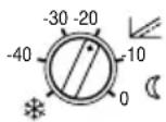
In the position *(frost protection), the heating unit remains switched off as long as the outside temperature is above +4 °C. Burner and pump are not in operation (see Section 7.2).
The night reduction determines by how many K (°C). The heating curve is shifted parallel downward in reduced operation (the broken line in Fig. 4). Values between 0 and -40 K (°C) can be set.
ip Select a setting with which the desired temperature reduction is achieved.
Note: A reduction of the flow temperature by 5 K (°C) results in approx. 1 K (°C) room temperature reduction.
7.4 TA 211 E with Time Switch and TW 2 Remote Control (Accessory) (not in UK)
The TW 2 Remote Control is effective only when the operating mode switch (b) of the TA 211 E is in the position. If this is the case, the operating mode can be set with the operating mode switch on the remote control.
Set the base point for normal operation and night reduction as described in Section 7.3.
In the position of the operating mode switch on the TW 2, a fixed reduction value of 25K ( ^ ) is pre-programmed. The reduction value set on the adjustment knob of the TA 211 E is not effective in this case.
Should the reduction value of 25 K (°C) be too high or too low for longer absences, the operating mode switch (b) of the TA 211 E can be temporarily set to the © position and any desired reduction value selected on the knob (d).
A detailed functional description can be found in the operating instructions of the TW 2.
7.5 TA 211 E with TFQ 2 or TFP 3 Remote Control (Accessory) (not in UK)
The remote control is effective only when the operating mode switch (b) of the TA 211 E is either in the position Ⓛ The operating mode can then be set exclusively by means of the operating mode switch on the remote control.
Note: The degree of flow temperature reduction is also set exclusively on the TFQ 2/TFP 3.
A detailed functional description is provided with the remote control.
8 Programming the time switch (Accessory)
The TA 211 E is delivered without a time switch.
For the operation of the time switch, refer to the associated operating instructions.
9 General Notes
Heating units that can be operated with the TA 211 E Regulator are equipped with an automatic device that limits the switching frequency in two-point operation of the burner.
For more detailed information, refer to the installation instructions of the heating unit.
A frost protection circuit is also built into the switching box of the heating unit that keeps the flow temperature above +10 °C.
10 Malfunction
A malfunction of the regulator or a faulty connection are indicated with an error code on the control panel. The following error codes are caused by the regulator TA 211 E:
- “AC” Contact failure or malfunction of the regulator.
- “CC” Contact failure or defect external temperature sensor.
Table de matières
Service abaisse- ment permanent
7.2.3 Service permanent normal
WS Warmwaterreservoir
RK Terugslagklep

2975-04a.1/O 2975-04b.1/O

natural_image
Simple line drawing of a mechanical setup with two hanging components and a vertical rod (no text or symbols)2975-04c.1/O
natural_image
Pure geometric diagram with lines and shapes, no text or symbols present2975-04d.1/O

natural_image
Simple line drawing of a door with a small window on top (no text or symbols)2975-04e.1/O 2975-04f.1/O

natural_image
Simple line drawing of a two-panel window frame with a small icon below (no text or symbols)
natural_image
Diagram of airflow or heat transfer around a rectangular structure with directional arrows (no text or symbols)2975-04g.1/O
6

flowchart
graph TD
    AF["AF"] --> TA211E["TA 211 E"]
    TA211E --> FB["FB"]
    TA211E --> SF["SF"]
    TA211E --> E["E"]
    TA211E --> RK["RK"]
    TA211E --> 230V["230V 50Hz"]
    TA211E --> EU2D["EU 2D / DT 2 (EU 3T / DT 1)"]
    EU2D --> WS["WS"]
4100-12.2/G
7
4100-13.2/G
8
flowchart
graph TD
    A["AF"] --> B["4100-09.2/G"]
    B --> C["St9 TA-Modul"]
    C --> D["ST1"]
    C --> E["ST2"]
    C --> F["ST5"]
    C --> G["EU 2D / DT 2 / EU 3T / DT 1"]
    C --> H["6"]
    style A fill:#f9f,stroke:#333
    style B fill:#ccf,stroke:#333
    style C fill:#cfc,stroke:#333
    style D fill:#fcc,stroke:#333
    style E fill:#cff,stroke:#333
    style F fill:#ffc,stroke:#333
    style G fill:#fcc,stroke:#333
    style H fill:#cff,stroke:#333
9

flowchart
graph TD
    TW2["1 2 3 4"] -->|3 4| AF["AF"]
    AF -->|4100-10.2/G| TA211E["TA 211 E"]
    TA211E -->|1 3 4 A F| ST2["ST2"]
    ST2 -->|1 3 4 A F| TA211E
    TA211E -->|3 4| ST9["ST9 TA-Modul"]
    ST9 -->|6| EU2D["EU 2D / DT 2 / EU 3T / DT 1"]
    EU2D -->|4(3)| ST5["ST 5"]
    ST5 -->|4(3)| EU2D
    TW2 -->|4100-10.2/G| TS1["ST1"]
    TS1 -->|4(3)| EU2D
    style TW2 fill:#f9f,stroke:#333
    style TA211E fill:#ccf,stroke:#333
    style ST9 fill:#cfc,stroke:#333
    style EU2D fill:#fcc,stroke:#333
    style ST5 fill:#cff,stroke:#333
10

11

12

13

14

15


BOSCH
Bosch Thermotechniek B.V.
Postbus 379
7300 AJ Apeldoorn
Tel: +31 (0) 55 - 543 43 43
Fax: +31 (0) 55 - 543 43 44
www.boschcvketels.nl
infott@nl.bosch.com

- Deutsch
- Français
- Inhaltsverzeichnis
- Sparautomatik
- Safety Notes
- Application
- Items Supplied
- Accessories
- Mounting
- Mounting of the Outdoor Temperature Sensor AF (Figures 3 and )5
- Notes:
- Mounting the Regulator (Figures 11 and 15)
- Mounting the Accessories
- Electrical Connection
- Electrical Connection of the Outside Temperature Sensor (AF)
- Electrical Connection of Accessories (Figure 8 10)
- Time Switch
- Remote Control (not in UK)
- Mechanical Flow Temperature Limiter
- Closing the Switching Box
- Placing into Operation
- Operation of the Regulator
- Outside temperature for boiler switching off point (a)
- Operating Mode Switch (b)
- Continuous Reduced Operation
- Continuous off with frost protection function
- Continuous reduced operation
- Timed Switching
- Timed economy heating
- + -30 -20 Timed se back Operation
- Continuous Normal Operation
- Setting the Heating Curve
- Base Point Adjustment (c)
- Adjustment of the Maximum Feed Temperature (e)
- TA 211 E with Time Switch and TW 2 Remote Control (Accessory) (not in UK)
- TA 211 E with TFQ 2 or TFP 3 Remote Control (Accessory) (not in UK)
- Programming the time switch (Accessory)
- General Notes
- Malfunction
- Table de matières
- Service abaisse- ment permanent
- Service permanent normal
- BOSCH
Brand : BOSCH
Model : TA 211 E
Category : Thermostat