
OR30 OT - Thermostat BOSCH - Free user manual and instructions
Find the device manual for free OR30 OT BOSCH in PDF.


| Product Type | Room Thermostat |
| Model | OR30 OT |
| Brand | Bosch |
| Power Supply | 2 x AA batteries (not included) |
| Battery Life | Up to 1 year |
| Display | LCD screen with backlight |
| Dimensions (W x H x D) | 100 x 100 x 30 mm |
| Weight | 200 g |
| Mounting | Wall-mounted (screws and plugs included) |
| Compatibility | Most gas, oil, and electric heating systems (24V) |
| Programmable | Yes, 7-day programmable with up to 6 time periods per day |
| Temperature Range | 5°C to 35°C (settable) |
| Accuracy | ±0.5°C |
| Frost Protection | Yes, automatic at 5°C |
| Holiday Mode | Yes, with adjustable duration |
| Child Lock | Yes, keypad lock function |
| Open Window Detection | Yes, automatic shutoff |
| IP Rating | IP30 |
| Cleaning | Wipe with a dry, soft cloth |
| Replacement Parts | Batteries (AA), wall plugs |
Frequently Asked Questions - OR30 OT BOSCH
User questions about OR30 OT BOSCH
0 question about this device. Answer the ones you know or ask your own.
Ask a new question about this device
Download the instructions for your Thermostat in PDF format for free! Find your manual OR30 OT - BOSCH and take your electronic device back in hand. On this page are published all the documents necessary for the use of your device. OR30 OT by BOSCH.
USER MANUAL OR30 OT BOSCH
8 733 201 137-00.10
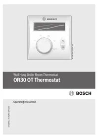
Wall Hung Boiler Room Thermostat
OR30 OT Thermostat

BOSCH
Operating Instruction
Contents
1 Symbols and safety precautions .... 3
1.1 Key to symbols 3 1.2 Safety instructions 4
2 Delivery scope 5
3 Product instruction 6
3.1 Proper use 6 3.2 Technical parameters 6 3.3 Accessories 6 3.4 Main functions and features 7 3.5 Cleaning 7
4 Product description 8
5 Installation 9
5.1 Installation instructions 9 5.2 Installation of room thermostat 9 5.3 Installation steps 10
6 Operation instructions 14
6.1 Temperature calibration 14
7 Applicable model 15
1 Symbols and safety precautions
1.1 Key to symbols
Warnings

Warnings in this document are identified by a warning triangle printed against a grey background. Keywords at the start of a warning indicate the type and seriousness of the ensuing risk if measures to prevent the risk are not taken.
The following keywords are defined and can be used in this document:
- NOTICE indicates a situation that could result in damage to property or equipment.
- CAUTION indicates a situation that could result in minor to medium injury.
- WARNING indicates a situation that could result in severe injury or death.
- DANGER indicates a situation that will result in severe injury or death.
Important information

This symbol indicates important information where there is no risk to people or property.
Additional symbols
Symbol Explanation
▶ Step in an action sequence
→ Cross-reference to another part of the document
- List entry
- List entry (second level)
Table 1
1.2 Safety instructions
General safety instructions
▶ Follow the manual to ensure complete functionality. ▶ Install and use heaters and other accessories according to the manual. ▶ Accessories can only be installed by an authorized installer. ▶ The accessories must not be connected to a power supply of 220~240V. ▶ Before installing the accessories: Interrupt the power supply of heaters and other members of the bus (220~240V AC). ▶ Inform the working method of the accessories and guide customers to operate. ▶ The heater is switched on when freezing danger occurs, and comply with anti-freezing tips.
Damage caused by operational errors
Operational errors may cause personal injury and/or property damage.
▶ Ensure that children do not operate and/or play with the equipment under unattended circumstances. ▶ Ensure that the equipment can only be touched by personnel who can operate the equipment correctly.
2 Delivery scope

Fig. 1
[1] OT controller [2] Installation package (screws...) [3] Manual instruction
3 Product instruction
OR30 room thermostat has the advantages of easy operation and practicality.
3.1 Proper use
Please carefully read this manual before using, and operate according to requirements specified in the manual.

Error conditions please refer to error code introduction of wall hung boiler.
3.2 Technical parameters
| Voltage 3V±10% | |
| Temperature range 5~30°C | |
| Measure precision ±1°C | |
| Dimensions | 86 × 86 × 28mm |
| Ambient temperature -5°C~40°C | |
| Load current 0.5A~125VAC 2A~30VDC | |
| Material & Color Ivory ABS |
Table 2
3.3 Accessories
- Manual instruction
- Installation package
- Screws*2
- Anchors*2
3.4 Main functions and features
- Set temperature by knob
- Display current temperature
- Boiler working condition • Memory function in case of power-down
- Fault display function
- Reset function for boiler fault
- Temperature correction
- Check the CH and DHW water temperature
- Set the parameter of CH and DHW water • Control the flame so as to make the room temperature comfortable
3.5 Cleaning
▶ Use wet cleaning cloth to wipe the housing of controller. Must not use irritant or corrosive detergent.
4 Product description

Fig. 2
[1] Operation condition
[2] Room temperature icon
[3] Up \Exit \Reset
[4] Down\menu
[5] Temperature knob
[6] Current room temperature
[7] DHW (Domestic heating water)
[8] CH (heating water)
[9] Anti-freezing
5 Installation
5.1 Installation instructions
• Isolate the appliance from the electrical supply. - Avoid installing the thermostat close to fridge, radiator, kitchen, computer, window, doorway or other over-cooling, over-heating and temperature changed frequently areas. The best position to install the thermostat is a dry place which can precisely reflect room temperature, and has low interference. - Ambient temperature: -5°C to 40°C - Relative humidity: Max RH 85% (23 °C) • Altitude: Less than 2000 Meter
5.2 Installation of room thermostat
The standard mounting holes are at the back of thermostat, and user can install the thermostat on the wall with them. Open the thermostat and install the thermostat according to the letters given by the follow picture.

Fig. 3
10 Installation
5.3 Installation steps
▶ Finger-tighten the middle part of three edges of back cover, as shown in the figure, to make the three edges recessed, and then remove back cover (see Fig. 4).

Fig. 4
▶ Drill two installing holes on the wall, and push swell plastic button in holes. Use screws to fix back cover onto wall surface (see Fig. 5) (Distance between two holes is 60mm, please try to make uniform height).

Fig. 5
12 Installation
▶ Use a screwdriver to connect the OT cable to the product connector base, as shown in Fig. 6 (regardless of cable positive and negative electrodes).

Fig. 6
▶ Fix the product on the back cover, as shown in Fig. 7.

Fig. 7
6 Operation instructions
The OR30 room thermostat has the advantages of easy operation and practicality. Its functions are operated by two keys and a knob.
- Fault reset: Press the "UP" key to reset if a fault code occurs.
- Check CH/DHW temperature: Press the "DOWN" key to check the CH/DHW temperature, and then press the "UP" key to exit.
- Set target room temperature: Increase or decrease the room temperature by rotating the knob.
- Set the target temperature of DHW: Press the "DOWN" key twice to check the DHW temperature, then press "DOWN" and "UP" simultaneously to set the target temperature of DHW. Adjust the target point with the "DOWN" and "UP" keys. Press "DOWN" and "UP" once simultaneously to exit.
- Temperature calibration: Press "DOWN" and "UP" simultaneously for 5 seconds to start temperature calibration. The LCD shows the battery icon, and calibrate the temperature with the "DOWN" and "UP" keys. Press "DOWN" and "UP" simultaneously once to exit.
- Default reset: Press the "UP" key for 5 seconds until "LOD" blinks. Press any key to exit.
- The temperature displayed on the thermostat may differ from that of a thermograph. The test methods of a thermograph and a thermostat are different. In general conditions, the thermostat's temperature sensor is more precise than a thermograph. Due to differences in regions and environments, the thermostat may have a slight deviation. If this deviation is large (>5 °C), you can use "temperature calibration" to adjust (see part 6.1).
6.1 Temperature calibration
Due to regional and environmental differences, the thermostat may have a slight deviation. Users can adjust the temperature through “temperature calibration”.
▶ Press the up (P8) and down (P9) keys together to enter temperature correction, and the battery icon will flash on the LCD. ▶ Adjust the value using the “up (P8)” and “down (P9)” keys. If the temperature difference is not very obvious, this function is not recommended.

There is a 2 °C inaccuracy in household thermometers.
7 Applicable model
| Boiler model Model No. Serials | ||
| Eurosmart MINI | L1P18 (WBN6000-16C) | 7716482002 |
| N1P17 (WBN6000-15S) | 7716482003 | |
| “New” Eurostar | L1P20-WBN6000 -18CRN S5500 | 0T1010044700023338 |
| N1P20-WBN6000 -18HRN S5500 | 0T1010044700023332 | |
| L1P27-WBN6000 -24CRN S5500 | 0T1010044700023339 | |
| N1P27-WBN6000 -24HRN S5500 | 0T1010044700023333 | |
| L1P31-WBN6000 -28CRN S5500 | 0T1010044700023340 | |
| N1P31-WBN6000 -28HRN S5500 | 0T1010044700023334 | |
Table 3
Robert Bosch (Australia) Pty Ltd
Thermotechnology Division
1555 Centre Road
Clayton Victoria 3168
Australia
Phone: 1300 30 70 37
Fax: 1300 30 70 38
www.bosch-climate.com.au
New Zealand
Phone: 0800 54 33 52
Fax: 0800 54 33 55
www.bosch-climate.co.nz

- WALL HUNG BOILER ROOM THERMOSTAT
- OR30 OT THERMOSTAT
- CONTENTS
- SYMBOLS AND SAFETY PRECAUTIONS
- DELIVERY SCOPE
- PRODUCT INSTRUCTION
- PRODUCT DESCRIPTION
- INSTALLATION
- OPERATION INSTRUCTIONS
- APPLICABLE MODEL
- KEY TO SYMBOLS
- WARNINGS
- IMPORTANT INFORMATION
- ADDITIONAL SYMBOLS
- SYMBOL EXPLANATION
- SAFETY INSTRUCTIONS
- GENERAL SAFETY INSTRUCTIONS
- DAMAGE CAUSED BY OPERATIONAL ERRORS
- PROPER USE
- TECHNICAL PARAMETERS
- ACCESSORIES
- MAIN FUNCTIONS AND FEATURES
- CLEANING
- INSTALLATION INSTRUCTIONS
- INSTALLATION OF ROOM THERMOSTAT
- INSTALLATION STEPS
- TEMPERATURE CALIBRATION
Brand : BOSCH
Model : OR30 OT
Category : Thermostat