
FW 200 - Thermostat BOSCH - Free user manual and instructions
Find the device manual for free FW 200 BOSCH in PDF.
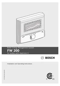


| Product Type | Digital Room Thermostat |
| Model | FW 200 |
| Brand | Bosch |
| Dimensions (H x W x D) | 86 x 86 x 30 mm |
| Weight | 0.15 kg |
| Power Supply | 2 x AA batteries or 24 V AC |
| Display | Backlit LCD with temperature and settings |
| Temperature Control Range | 5°C to 35°C |
| Accuracy | ±0.5°C |
| Programming | Weekly programmable, up to 6 time periods per day |
| Functions | Frost protection, holiday mode, manual override, child lock |
| Control Type | On/Off or modulating (PID) |
| Compatibility | Gas, oil, electric, heat pump systems |
| Wireless | No (wired connection) |
| Protection Class | IP20 (indoor use only) |
| Cleaning and Maintenance | Wipe with a soft, dry cloth; do not use solvents |
| Safety Features | Frost protection, low battery indicator, software lock |
| Spare Parts Availability | Replacement batteries, wall plate, screws |
| Repairability | Battery replacement by user; other repairs by qualified technician |
| General Information | User manual available for download in PDF |
Frequently Asked Questions - FW 200 BOSCH
User questions about FW 200 BOSCH
0 question about this device. Answer the ones you know or ask your own.
Ask a new question about this device
Download the instructions for your Thermostat in PDF format for free! Find your manual FW 200 - BOSCH and take your electronic device back in hand. On this page are published all the documents necessary for the use of your device. FW 200 by BOSCH.
USER MANUAL FW 200 BOSCH
Boiler Energy Management System
FW 200
for boilers with Heatronic 3

BOSCH
Installation and Operating Instructions
Overview of controls and symbols

Fig. 1 Controls

Fig. 2 Default display for heating circuit 1 (example for wall mounting)

Fig. 3 Default display for heating circuit 2 (example for wall mounting)
| Controls | |
| 1 Turning dial in + direction (clockwise): scrolls menu/information up or increases setting value | |
| Turning dial in - direction (counter-clockwise): scrolls menu/information down or decreases setting value | |
| Pressing dial opens menu or confirms setting/value or switches heating zone | |
| 2 Mode selector for heating zones: | |
| auto | Automatic operation mode |
| Continuous Comfort mode | |
| Continuous Economy mode | |
| Continuous Frost Protection mode | |
| 3 : Jumps forward to the next switch point and the associated operating mode = Comfort, Economy, Frost Protection for the heating zone. | |
| 4 : Activate DHW mode immediately. The DHW tank is heated to the desired temperature for 60 minutes or, with combi boilers, Comfort mode is activated for 30 minutes. | |
| 5 : Open/close menu | |
| 6 : Show settings | |
| 7 : Delete/reset setting | |
| 8 : Return to next menu up | |
Tab. 1
| Symbols | |
| 74°F | Current room temperature (only when mounted on the wall in the living space) |
 | Flashing segment: Time now (between 01:45pm and 02:00pm) (13:45 - 14:00) |
 | Solid segments: time set for operating mode Comfort today (1 segment = 15 min) |
 | Empty segments: time set for operating mode Economy today (1 segment = 15 min) |
 | No segments: time set for operating mode Frost Protection today (1 segment = 15 min) |
 | Operating mode Comfort for heating zone |
 | Operating mode Economy for heating zone |
| [EXZ6] | Operating mode Frost Protection for heating zone |
| [ZZZZ] | Automatic mode for heating zone |
 | Vacation mode |
| [Ocm] | Burner operation on display for heating zone 1 |
| [OKM] | Operation on display for heating zone 2 |
| [THX] | Return to previous menu up |
| [OKZ0] | Other display information (menu options) are available. They can be viewed by turning the dial |
Tab. 2
The information in the default display (see Fig. 2 or 3) and the operation always apply only to the current heating zone.
To display the information applicable for the other heating zone:
While in the default display, use to switch to the other heating zone.
Contents
1 Explanation of symbols and safety information ....7
1.1 Explanation of symbols ..... 7 1.2 Safety instructions 8
2 Information about the appliance ..... 9
2.1 Scope of delivery 9 2.2 Technical specifications ..... 10 2.3 Cleaning 10 2.4 Supplementary accessories ..... 11 2.5 Installation example ..... 12
3 Installation (for installers only) ..... 14
3.1 Installation 14 3.1.1 Installation in boiler 14 3.1.2 Wall mounting 15 3.1.3 Mounting of the outdoor temperature sensor .....17 3.1.4 Mounting other accessories ..... 18 3.1.5 Disposal 18 3.2 Making the electrical connections . 19 3.2.1 Electrical connection in boiler .... 19 3.2.2 Electrical connection to wall ..... 19
4 Commissioning (installers only) ..... 20
5 Operation 21
5.1 Heating and DHW programs ..... 22 5.1.1 General information 22 5.1.2 Weekly programs 22 5.1.3 Structure of programs ..... 22 5.2 Setting programs 23 5.2.1 Viewing on the display and navigating through the menu .....23 5.2.2 Setting and changing switch points and operating modes .....24 5.3 Manual setting of operating modes 27 5.3.1 Selecting the operating mode for heating....27 5.3.2 Changing heating mode before the programmed time (bringing forward the next switch point) .....28
5.3.3 Changing the domestic hot water operating mode (time-limited) . . . 28 5.3.4 Vacation mode 28 5.4 Changing the specified room temperature 30 5.4.1 Permanently changing the specified room temperature ..... 30 5.4.2 Changing the specified room temperature for a limited period . 30
6 MAIN MENU settings 31
6.1 MAIN MENU summary and settings 31 6.1.1 MAIN MENU: Vacation ..... 32 6.1.2 MAIN MENU: Heating 33 6.1.3 MAIN MENU: Domestic hot water . 35 6.1.4 MAIN MENU: General settings . . . . 37 6.1.5 MAIN MENU: Solar 38 6.2 Heating program 39 6.2.1 Timer programs for heating ..... 39 6.2.2 Temperature levels for operating modes and heating rate ..... 41 6.3 DHW program 42 6.3.1 DHW program operating modes . . 43 6.3.2 Timer program for domestic hot water with combi boiler ..... 44 6.3.3 Time/temperature level program for domestic hot water via tank .. 45 6.3.4 Timer program for DHW recirculation pump (systems with domestic hot water tank only) 46 6.3.5 Parameters for domestic hot water 47 6.3.6 Thermal disinfection of domestic hot water 48 6.4 General settings 49 6.4.1 Time, Date ..... 49 6.4.2 Display formats 49 6.4.3 Key lock 49 6.4.4 Language ..... 49 6.5 Solar settings 50
7 Viewing information 52
8 Menu settings INSTALLER SETTINGS (for installers only) ..... 57
8.1 INSTALLER SETTINGS menu summary and settings ..... 57
8.1.1 INSTALLER SETTINGS: System configuration .... 58
8.1.2 INSTALLER SETTINGS: Heating parameters ..... 59
8.1.3 INSTALLER SETTINGS: Solar system config .... 60
8.1.4 INSTALLER SETTINGS: Solar sys parameters ..... 61
8.1.5 INSTALLER SETTINGS: Fault history .... 63
8.1.6 INSTALLER SETTINGS: Cust service address ..... 63
8.1.7 INSTALLER SETTINGS: System info .... 64
8.1.8 INSTALLER SETTINGS: Slab drying 65
8.1.9 INSTALLER SETTINGS: Output test 65
8.2 Configuring the heating system ... 66
8.3 Parameters for heating ..... 67
8.3.1 Parameters for the entire heating system 67
8.3.2 Heating circuit parameters ..... 68
8.4 Configuring the solar thermal system ..... 72
8.5 Parameters for solar thermal system ..... 73
8.5.1 Commissioning the solar thermal system ..... 73
8.5.2 Resetting parameters for solar thermal system ..... 73
8.5.3 Parameters for the standard solar thermal system .....73
8.5.4 Parameters for solar heating boost system 74
8.5.5 Parameters for the second collector field ..... 75
8.5.6 Parameters for the solar recharge system ..... 76
8.5.7 Parameters for a high/low priority system....76
8.5.8 Parameters for an external heat exchanger 78
8.5.9 Parameters for thermal disinfection 79
8.5.10 Parameters for solar optimization . 80
8.6 Fault history ..... 82
8.7 Viewing and entering the customer service address 82
8.8 Viewing system information ..... 83
8.9 Slab drying function ..... 83
8.10 Test of the actuators on the system 85
9 Troubleshooting 86
9.1 Troubleshooting with display .... 86
9.2 Troubleshooting without using display 94
10 Energy saving tips 96
11 Environmental protection ..... 97
12 Commissioning log for the heating system 98
13 Individual timer program settings .... 99
13.1 Heating program for the heating circuit 1 and heating circuit 2 .... 99
Guide to instructions

Deliver all documentation enclosed to the user.
If you ...
• ... are looking for the safety instructions and an explanation of the symbols, refer to Section 1. •... are looking for a summary of the design and function of this accessory, refer to Section 2. There you will also find the technical data. • ... are an INSTALLER and want to know how to install, wire up and commission this accessory, then go to Sections 3 and 4. - ... want to know how to operate and program this accessory, refer to Sections 5, 6 and 13. There you will also find summaries of the default settings and setting ranges for the menus. There are also tables for writing down your settings. •... want to view information about the heating system, refer to Section 7. • ... are an INSTALLER and want to make installer settings or view system information, refer to Section 8. There you will also find summaries of the default settings and setting ranges for the menus. There are also tables for making a note of your settings. • ... are looking for troubleshooting tables, refer to Section 9. • ... are seeking tips about energy efficiency, refer to Section 10. • ... are looking for a particular reference in the document, have a look in the Index at the end of this booklet.
1 Explanation of symbols and safety information
1.1 Explanation of symbols
Warnings

Warnings are indicated in the text by a warning triangle and a gray background.

In case of danger due to electric shock, the exclamation point on the warning triangle is replaced with a lightning symbol.
Signal words at the beginning of a warning are used to indicate the type and seriousness of the ensuing risk if measures for minimizing damage are not taken.
- NOTE indicates that minor damage to property may occur.
- CAUTION indicates possible minor to medium personal injury.
- WARNING indicates possible severe personal injury.
- DANGER indicates that severe personal injury may occur.
Important information

Important information that presents no risk to people or property is indicated with this symbol. It is separated by horizontal lines above and below the text.
Additional symbols
Symbol Meaning
▶ Sequence of steps
→ Cross-reference to other points in this document or to other documents
- Listing/list entry
- Listing/list entry (2nd level)
Tab. 3
Conventions used in these instructions for representing the menu structure:
- Individual menu levels are separated by the > symbol, e.g. Vacation > Start
- Parameters that can be set/selected on a menu are marked with a bullet point • . •The operation of a control is indicated by the symbol for the control:
- means turn dial
- means press dial
- means press and release Menu button
- means press and release Info button
- means press and release Delete/Reset button
- means press and release Menu Up button
- means press and release Advance button
- means press and release DHW single charge button
1.2 Safety instructions
▶ To ensure proper function, follow these instructions. ▶ Install and start up the boiler and all accessories according to the associated instructions. ▶ Only have this accessory installed by a trained and certified installer. ▶ Use this accessory exclusively in conjunction with the controllers and heating appliances listed. Follow the connection diagram! ▶ Never connect this accessory to 120 VAC line voltage. ▶ Prior to mounting this accessory: Isolate the boiler from the power supply (120 VAC) using the emergency shut-off switch or the heating system circuit breaker. Electrical components must be installed by a trained electrician and the installation must meet the National Electric Code as well as all applicable local codes and regulations. ▶ Provide a dedicated circuit breaker for the boiler and heating system rated at least 15 A. ▶ All line voltage wiring must use at least AWG14 size cables. ▶ In case of wall mounting: never mount this accessory in wet areas. ▶ Instruct customers about the functions and operation of this accessory. ▶ Risk of scalding during thermal disinfection: Due to DHW temperatures occurring in excess of 140 °F (60 °C), Bosch strongly advises to install a DHW thermostatic mixing valve. ▶ When there is a risk of frost, leave the boiler switched on and follow the frost protection information.
2 Information about the appliance

The FW 200 can only be connected to a boiler with BUS-enabled Heatronic 3.
• These controls are used to display device and system information and to change the settings shown. • In connection with the IPM 2 module the controls are an outdoor reset control for two heating zones and DHW provision with time programs:
- Central heating: SIX weekly heating programs with six switch points per day are programmable (one program is active).
- Hot water: weekly DHW program with six switch points per day.
- Options:
- Remote control FB 100 with IPM2 module for expansion up to max. 4 heating zones. - Module ISM 2 for solar water heating and solar heating boost.
• The controls have a power reserve sufficient for at least 6 hours of operation. If the controls are without power for a period longer than the power reserve, then the time and date will be deleted. All other settings are kept.
• Installation options:
- In the boiler with BUS-enabled Heatronic 3 - Wall-mounted with BUS link to boiler with BUS-enabled Heatronic 3
2.1 Scope of delivery
Fig. 4 Scope of delivery
1 Controls top section 2 Base for wall-mounting 3 Slide cover 4 Installation and operating instructions 5 Outdoor temperature sensor with mounting kit
2.2 Technical specifications 2.3 Cleaning
| Dimensions Fig. 10, page 15 | |
| Rated voltage 10...24 VDC | |
| Current draw (excluding backlight) | 6 mA |
| Controller output 2-wire BUS | |
| Permissible ambient temperature | 32 ... +122 °F(0 ... +50 °C) |
| Protection class III | |
| Protection level:- installed in Heatronic 3- wall-mounted | IPX2DIP20 |
 | |
Tab. 4 Specifications
| °F °C Ω | AF | °F °C Ω | AF | ||
| -4 | 20 2392 | 39 4 984 | |||
| 3 | - | 1 | 6 | 2088 46 8 842 | |
| 10 | -12 | 1811 | 54 | 12 | 720 |
| 18 - 8 | 1562 | 61 16 | 616 | ||
| 25 - 4 | 1342 | 68 20 | 528 | ||
| 32 | ±0 | 1149 | 75 | 24 | 454 |
Tab. 5 Measurement values outdoor temperature sensor
If necessary, use a damp cloth to wipe the controls housing. Never use aggressive or acidic cleaning agents.
2.4 Supplementary accessories
See also the price list.
- IPM 2: module for control of up to two mixed heating zones. Control of one unmixed heating zone in the heating system possible.
- ISM 2: module for controlling solar water heating and solar heating boost.
- FB 100: Remote control with plain text display for the control of one mixed or non-mixed heating zone.
2.5 Installation example
![graph TD subgraph_System_2_System["System 2 Option A"] A1["FK"] --> A2["FK"] A3["FK"] --> A4["FK"] A5["CV"] --> A6["PA"] A7["RE"] --> A8["SP"] A9["CV"] --> A10["SP"] A10 --> A11["RE"] A12["SWC"] --> A13["DSWUC"] A13 --> A14["DSWUC"] A15["WSc"] --> A16["DSWUC"] A17["DSWUC"] --> A18["DSWUC"] end subgr…](/content/2026/06/1276483/images/a21fa9257c7285f3e9fe476375b96e9bbf978c6ce1f18dacf2a82a63f6b87f6a.jpg)
Fig. 5 Schematic diagram of system (diagram for installation purposes included in the planning documents)
AF Outdoor temperature sensor
CV Flow check valve
DWU1 Valve for return flow boost on the heating network
DWUC Valve for high/low priority storage systems (option C)
FB 100 Remote control
FK Solar collector
FW 200 Outdoor reset controls with solar controls
GZT Boiler
HK1...4 Heating zones
HP Boiler circulator
IPM 2 Module for two heating zones
ISM 2 Solar module for solar water heating and heating boost
KW Cold water connection
M1...4 Mixing valve motor
MF1...4 Supply temperature sensor for mixed heating zone
Option A 2nd collector field
Option C High/low priority system
Option E Thermal disinfection of the solar tank
P1...4 Heating zone pump
PA Solar circuit pump (option A)
PE Circulation pump for thermal disinfection
P/S P/S Piping (Low-loss header)
RE Flow rate adjuster with indicator
SF Storage tank temperature sensor (NTC)
SP Solar circuit pump 1st collector field
System 2 Heating boost and solar DHW heating
T1 Collector temperature sensor for 1st collector field
T2 Buffer storage tank temperature sensor, bottom
T3 Buffer storage tank temperature sensor, top
T4 Temperature sensor heating network return for solar heating boost
TA Collector temperature sensor (option A) for 2nd collector field
Tc DHW-side storage tank temperature sensor, bottom
TB 1...4 Temperature limiter
VF System supply temperature sensor
1) The FW 200 can optionally be installed in the boiler or mounted on the wall. If the FW 200 is installed in the boiler, a FB 100 in the first heating zone is possible.
2) Optional
3 Installation (for installers only)
The detailed system diagram for mounting the hydraulic components and the associated control devices can be found in the planning documents or specifications.

DANGER: Risk of electric shock!
▶ Prior to mounting this accessory: Isolate the boiler from the power supply (120 VAC) using the emergency shut-off switch or the heating system circuit breaker.
3.1 Installation
3.1.1 Installation in boiler
▶ Detailed description of boiler components, see boiler installation instructions. ▶ Remove the cover.

Fig. 6
▶ Remove cover plate and dummy cover.

Fig. 7
▶ Insert top section in slots.

Fig. 8
▶ Click top section into place and mount cover plate.

Fig. 9
3.1.2 Wall mounting
The performance of the controls depends on where they are installed.
The installation site (primary room) must be suitable for controlling the heating zones assigned.
▶ Select the installation location.

Fig. 10

The mounting surface on the wall should be level.
▶ Remove the top section and slide cover from the base.

Fig. 11
16 | Installation (for installers only) US/CA
▶ Mount the base.

Fig. 12
▶ Make the electrical connections (→ Fig. 16 or 17 on page 19). ▶ Refit top section and slide cover on base.

Fig. 13
3.1.3 Mounting of the outdoor temperature sensor
Performance depends on installation location of outdoor temperature sensor AF.
▶ Select the installation location.
Fig. 14
18 | Installation (for installers only) US/CA
▶ Remove cover. ▶ Attach sensor housing to external wall with two screws.

Fig. 15
3.1.4 Mounting other accessories
▶ Mount accessories according to code requirements and the installation instructions supplied.
3.1.5 Disposal
▶ Dispose of packaging in an environmentally responsible manner. ▶ When replacing components, dispose of the defunct parts in an environmentally responsible manner.
3.2 Making the electrical connections
3.2.1 Electrical connection in boiler
▶ Installation of the controls automatically produces BUS connection via the three contacts (→ Fig. 8 on page 14).

Fig. 16 Controls installed in boiler via BUS contacts in BUS-enabled Heatronic 3.

The controls recognize that the boiler is installed via the third contact.
3.2.2 Electrical connection to wall
▶For BUS connection use AWG 18 (0.75 mm²) cable and do not exceed 492 ft. (150 m) total length. ▶For the outdoor sensor AF use AWG 18 (0.75 mm²) cable and do not exceed 66 ft (20 m) total length. ▶Route all low-voltage cables separately from cables carrying line voltage to avoid inductive interference (minimum separation 4" (100 mm)). ▶In case of inductive external influences, use shielded cables.
This way, the cables are shielded against external influences (e.g. high-voltage cables, contact wires, transformer stations, radio and
TV devices, amateur radio stations, microwave devices, etc.).

Fig. 17 Controls connected to BUS-enabled Heatronic 3.

If the BUS cables feature different cross-sections:
▶Connect BUS link via a junction box.
![graph TD A["A"] -->|1| B1["B"] A -->|2| B2["B"] A -->|2| B3["B"] B1 -->|≥4" (≥100 mm)| B4["B"] B2 -->|≥4" (≥100 mm)| B5["B"] B3 -->|≥4" (≥100 mm)| B6["B"] B4 -->|6720 643 250-08.10| End["End"]](/content/2026/06/1276483/images/3af4b8739f6f40aced5c89def3baccb9c093eec3e4d0767799ae77459c279132.jpg)
Fig. 18 Connection of BUS links via junction box
A Junction box
B BUS devices
4 Commissioning (installers only)
For correct commissioning, it is essential that the following steps are carried out in the order shown.
- Set the DIP switch on IPM 2 in accordance with the details in the instructions supplied.
- Switch on the system.
- Set the DIP switch on FB 100 in accordance with the details in the instructions supplied.

The functions of the controls and the meanings of the symbols on the display are explained on pages 2 and 3.
- When commissioning for the first time or after a complete reset (factory reset), you must select the display language:
-Turn to select the language and press to confirm. (For how to change the language → Section 6.4.4 on page 49.)
- If the power reserve has run out, set the date and time as follows:
-Turn to select the hour and press to confirm. -Turn to select the minute and press to confirm. -Turn to select the year and press to confirm. -Turn to select the month and press to confirm. -Turn to select the day and press to confirm. (For how to change the date and time → Section 6.4.1 on page 49.)
- When the unit is first commissioned, automatic system configuration starts immediately after entry of the date and time.
- Wait for 60 seconds and then follow the instructions displayed.
-If automatic system configuration does not start of its own accord, start it from the menu → Section 8.2 on page 66.
- Adjust other settings to suit the specifics of the system, → Section 6 starting on page 31 and Section 8 starting on page 57.
- Fill and bleed the solar heating system according to its documentation and prepare it for commissioning as described in Section 8.4 on page 72.
- Adjust other settings to suit the specifics of the solar heating system, → Section 8.5 starting on page 73.
- Commission the solar heating system, → Section 8.5.1 on page 73.
- Inform the home owner and operator of the system about its function and method of operation as follows:
- Explain to the customer how the boiler and the controls work and how to operate them. - Inform the customer about the assigned heating zones, e.g., heating zone 1 is the radiator heating and heating zone 2 is the radiant floor heating. - Explain to the customer how the system works, e.g., time, operating modes for the heating zones, hot water temperature, time programs for heating zones and hot water. - Explain the use of the thermal disinfection function and the associated risk of scalding. - Hand all enclosed documents over to the user.
- Complete the commissioning log,
→ Section 12 on page 98.
5 Operation
Introduction
With the FW 200 heating controls, you can automatically control the room temperature and hot water temperature with a heating and DHW program created according to your own individual requirements.

Fig. 19 Example of heating program
If the controls are set according to your individual requirements, then you hardly need to use the menus for “day-to-day use”. Nevertheless, it is useful to be familiar with the basic use of the menus.
Therefore, you should read the whole of Sections 5.1 and 5.2 below and adjust a heating or DHW program to your own requirements as described in Section 5.2.2.
Making the effort may be worth your while! The procedure for changing a switch point will illustrate everything you need to know about navigating through the menus and entering settings. You can then program other settings in the same way with the help of information contained in sections 6 and 8.
The description of the menus reflects the arrangement of the menu options on the heating controls. The tables in sections 6.1, 7 and 8.1 show the whole menu structure. They also provide details of the adjustment ranges and default settings for all adjustable parameters. More information on the menu options can be found in Sections 6.2 to 6.5 for user functions, and Sections 8.2 to 8.9 for installer settings.
The description of a menu option starts with its menu path. That shows you how to reach the menu option concerned through the system of menus. The individual menu levels are separated by the > symbol, e.g., vacation > start.
Some menu options are dependent on others. In such cases, a page reference directs you to a description of the menu option on which it depends. Make use of such page references to other menu options. They will help you to understand associated functions.

The controls provide the option of setting the desired room temperature for the operating mode concerned. This temperature entry is not the actual room temperature. This is an orientation value that influences the required supply temperature for the heating zone.
5.1 Heating and DHW programs
5.1.1 General information
The programs for heating and domestic hot water enable you to achieve maximum energy savings while still enjoying optimum comfort in terms of room temperature and availability of domestic hot water. That is achieved, for instance, by deactivating water heating in the periods when nobody requires domestic hot water.
5.1.2 Weekly programs
All timer programs are set up to repeat every week. In the program memory you can store 6 switch points for every day in each program, i.e. a total of up to 42 switch points.
To simplify programming, you can set switch points for groups of days as well as for individual days.
The following groups of days are offered:
•All days
•Mon - Fri
•Sat + Sun
If, for example, you change and store a switch point for the option Mon - Fri, that change is simultaneously applied to all days from Monday to Friday.
5.1.3 Structure of programs
Programs for heating and domestic hot water are always structured in the same way. Up to six switch points (times) can be specified. A change of operating mode is specified for each switch point. The specified operating mode applies until changed by the next switch point.
Heating programs
Heating programs control heating operation. There are three modes for heating operation:
• Comfort

• Economy

• Frost (Frost protection)

For each of those operating modes, there is a specified room temperature stored on the FW 200 heating controls (see Section 5.4.1, page 30).
There are a total of six program spaces (A to F) available for heating programs. Each heating program contains the switch points for one week (weekly program). You can activate one of the heating programs for each heating zone.

Having several stored heating programs simplifies changing from one heating program to another, e.g. if your job involves periods when you work different shifts (night shift/day shift), or for vacation periods.
DHW programs
DHW programs operate differently according to the type of domestic hot water system:
- With combination boilers (boilers that produce domestic hot water instantaneously on demand) the DHW program switches between the following operating modes:
- On: if the Eco button on the boiler is not lit, hot water is available immediately on demand (Comfort mode).
- Off: the built-in plate heat exchanger in the boiler is not kept constantly hot (Eco mode); as a result energy is saved. In Eco mode, the hot tap has to be run for a short while before the water becomes hot.
- With appliances connected to a domestic hot water tank, the DHW program specifies the desired water temperature (set temperature).
- If the temperature measured in the domestic hot water tank is below the specified temperature, the tank is reheated.
- Once the specified temperature is reached (or exceeded), tank heating is stopped.

If the DHW program changes from a higher to a lower specified temperature, the water in the tank will not immediately cool to the lower temperature, i.e. water at a higher temperature will continue to be available for some time. However, the tank will not be reheated until the temperature falls below the new, lower specified temperature.
Recirculation program
The recirculation program specifies when a connected secondary recirculation pump for domestic hot water runs.
5.2 Setting programs

The functions of the controls and the meanings of the symbols on the display are explained on pages 2 and 3.
5.2.1 Viewing on the display and navigating through the menu
The user interface of the outdoor reset controls FW 200 is implemented as a menu system. Within that menu system, the various functions are arranged in a hierarchical structure. For greater clarity, the menu system is subdivided into three sections (MAIN MENU, INFO, and INSTALLER
SETTINGS). Each section can be accessed by its own button. The entire menu structure is shown in tabular form in Sections 6.1, 7 and 8.1.
To navigate through the menu system:
- Pressing menu opens the MAIN MENU. From any point within the MAIN MENU, pressing menu takes you back to the default display.
- Pressing info opens the INFO. From any point within the INFO menu, pressing info takes you back to the default display.
- Pressing and holding for at least 3 seconds opens the INSTALLER SETTINGS menu. From any point within the INSTALLER SETTINGS menu, pressing menu takes you back to the default display.
- The menu option/parameter selected in each case is highlighted
- Arrows in the left margin indicate that there is more information than can be shown on the display at once. It can be viewed by turning the dial
- Pressing the dial opens the submenu associated with the selected menu option/parameter or activates editing mode for the parameter (the parameter setting starts flashing).
- A flashing parameter value (e.g. switch point or operating mode)
—can be changed by turning the dial.

-can be reset to the factory settings by pressing 6. -is stored by pressing the dial. -remains unchanged if any other button apart from the dial is pressed.
- To return to the next menu up from a submenu:
-Select the menu option back and confirm by pressing the dial or
- Press .
5.2.2 Setting and changing switch points and operating modes
The way in which switch points and operating modes are set is always the same, the only differences are due to the various operating modes for each switch point.
The unit is supplied with programs for heating and domestic hot water already stored. It may also be that your installer has adjusted the programs to suit your requirements.
Changing (moving or deleting) a single switch point

The example below shows all the steps required to change a switch point in a heating program. If, instead, you want to change a switch point in a DHW program, open the DHW program in question (menu path: Domestic hot water > DHW program > Edit) and change the switch point in the same way.
▶Open flap.
The default display continues to be shown.

▶Press

The display lighting switches on and the main menu is displayed.

Turn the dial until the menu option Heating is selected.

Press.

The Heating menu is selected and the title bar shows the current menu name (in this case HEATING).

Turn the dial until the menu option Program is selected.
Press.

The Program menu is selected and the title bar shows the current menu name (in this case HEATING PROGRAM).

Turn the dial until the menu option Edit is selected.
Press.

The Edit menu is selected and the title bar shows the current menu name (in this case EDIT HEATING PROGRAM).

Turn until it points to the required heating program (e.g. A:Program A).
Press OK.
The heating program (e.g. A:Program A) is selected and the title bar shows the current menu name (EDIT PROGRAM A).

Turn until it points to the desired day (or group of days), e.g. Monday.
The segment ring always shows you the heating program if you display precisely one day (e.g. Monday) or if for a group of days, the switch points for all days in this group are the same (e.g. all switch points for Mon - Fri).

Press the dial to confirm the menu option Monday.
The next submenu (EDIT PROGRAM A MON) showing the programmed switch points and operating modes P1 to P6 is displayed.

▶ Turn the dial until the menu option P1 (= switch point 1) is selected.
▶ Press OK.
The switch point and corresponding segment on the segment ring start to flash.

▶ Turn until the desired switch point is displayed (e.g. 05:30 am or 05:30).
The ring of segments always shows the effect of the change on the heating program.

▶ Press OK.
The switch point is saved. The associated operating mode now starts flashing on the display.
▶ Turn until the required operating mode (e.g. Economy) is displayed.
The ring of segments always shows the effect of the change on the heating program.

▶ Press OK.
The operating mode is saved. Setting of P1 is now complete.
▶ You can now:
- change more switch points and operating modes in the same way, or
– finish programming and return to the basic display by pressing menu.
Using groups of days when programming
In many cases, you may want to program the same switch points for several days of the week, say for all working days. However, you may also want a different program for just one of those days.
Using the groups of days when programming enables you to complete the process in only a few steps.
For a group of days, e.g. Mon - Fri, program the switch points and operating modes that are the same for the majority of those days. Then change the switch points for the days that are different.
Copying ready-made programs
There are eight preprogrammed heating programs permanently stored on the heating controls. These cannot be applied directly to a heating circuit.
To be able to use the ready-made heating programs, you must copy them to one of the locations for heating programs (A to C), where you can also adapt them if necessary (see Section 5.2.2).

Programs A to F can also be copied to another memory slot.
Select the storage location to which the program is to be copied (A to F):
Open menu option Heating > Program > Edit > A:Program A ... F:Program F.
Press the dial twice.
The function Replace with preset program is selected and the option No is flashing.

Turn until the heating program to be copied is in the last line of the screen (e.g. All day).
Press OK
The heating program has now been copied.
Resetting an entire program (replacing with factory settings)
The unit is supplied with programs for heating and hot water already stored in the memory (see Section 13 on page 99).
Overwrite one of your own heating programs, A to F, as follows:
Bring up the relevant program (e.g., Menu: Heating > Program > Edit > C: Program C, or Menu: Domestic hot water > DHW program > Edit).
Turn the dial to select the option Reset factory settings.
Press OK.
The program has now been reset to the factory settings.
Resetting all settings (for installers only)
This function resets all settings on the MAIN MENU and the INSTALLER SETTINGS to their factory settings. Following such a reset, your installer will need to commission the system again!
If the default display is showing:
Simultaneously press and hold the buttons until the following warning message appears:

Continue holding until the following message appears:

Press the button.

All settings have now been reset to their factory settings with the exception of the date and time, which remain unchanged.
5.3 Manual setting of operating modes
The information in the default display (see Fig. 2 or 3 on page 2) and the operation always apply only to one heating zone.
To display the information applicable to the other heating zone:
During the default display, use the dial to switch to the other heating zone.
5.3.1 Selecting the operating mode for heating

In normal operation, always leave the dial in the addition position. By using correctly set heating programs, you can save energy and enjoy comfort.

Automatic (factory setting)
Switches automatically between the modes Comfort, Economy, and Frost according to the active heating program.

Constant heating
The controls constantly maintain the room temperature set for Comfort operating mode.

Constant economy
The controls constantly maintain the room temperature set for Economy operating mode.

Constant frost protection
The controls constantly maintain the room temperature set for Frost operating mode.
5.3.2 Changing heating mode before the programmed time (bringing forward the next switch point)
This function brings forward the time at which the operating mode Comfort, Economy, or Frost set for the next switch point becomes active.

The change applies only to the day on which you activate the function.
▶The function can be used in situations such as going to bed earlier, being away from home longer or coming back earlier.
▶If you are going to be away from home for several days, e.g. on vacation, you should use the Vacation function,
→ Section 5.3.4, page 28.
This function is only available if the heating circuit is not regulated via remote control FB 100 and the automatic operation also switched on.
▶Press and release to bring forward the next switch point and the associated operating mode Comfort ✪ / Economy 🌐 /
Frost for the selected heating circuit to the current time.
The segments around the perimeter of the display show the changed settings.
-or-
▶Press and hold and simultaneously turn the dial to change the next switch point.
The segments around the perimeter of the display show the changed settings.
To undo the change to the switch point:
▶Press

again
briefly.
5.3.3 Changing the domestic hot water operating mode (time-limited)

You can use this function if you need hot water outside the programmed times.
Press and release to activate hot water mode immediately.
The hot water tank is heated up to the temperature set in the DHW program for 60 minutes.
With a combi boiler, Comfort mode is activated for 30 minutes.
To undo the change to the domestic hot water mode:
Press

again
briefly.
5.3.4 Vacation mode
You can use this function if you want to set a constant operating mode for several days (e.g.
Frost without changing the heating program.
When the vacation program is active, the heating circuits and domestic hot water systems are operated according to the operating mode set in the vacation program (frost protection is automatically provided).
Press

The display lighting switches on and the main menu is displayed.

Press

The Vacation menu is selected and the title bar shows the current menu name (in this case Vacation).
Press the dial, the display changes to the Vacation menu and Start is selected. Now you can enter the date on which you want the vacation program to start. Enter the year, month and day one after the other and confirm your entry in each case by pressing the dial. Turn the dial so that End is selected. Press OK.
Now you can enter the date on which you want the vacation program to end. Enter the year, month and day one after the other and confirm your entry in each case by pressing the dial.

If you have set the vacation program to start on today's date, it will start immediately. If the date is in the future, the vacation program will start at 12:00am (00:00) on the set start date.
It will end at 11:59pm (23:59) hours on the set end date.
Programming of the vacation program is now complete. If required, you can adjust the heating and domestic hot water modes. The following operating modes are set in the factory settings:
• Heating circuit 1: Operating mode Frost. • Heating circuit 2: Operating mode Frost. - Domestic hot water: Operating mode Off or 60 °F (15 °C). • DHW recirculation pump: Off mode. • Thermal disinfection: Off mode.
When the vacation program is active, the standard display shows and the dates, e.g.
VACATION UNTIL 09/30/2010 (30.09.2010).
To cancel the vacation program early:
Select menu option Vacation > Start. Press the dial and then press. The display shows --/--/---- (--,--,----). Press the dial to store the setting.
1) DHW heating with combi boiler 2) DHW heating via hot water tank
5.4 Changing the specified room temperature

The controls provide the option of setting the desired room temperature for the operating mode concerned. This temperature entry is not the actual room temperature. This is an orientation value that influences the required supply temperature for the heating zone.
5.4.1 Permanently changing the specified room temperature
The following temperatures are stored as the factory settings for the specified room temperature:
- Operating mode Comfort ⚙️: 70 °F (21 °C)
- Operating mode Economy (C): 60 °F (15 °C)
- Operating mode Frost ⚙️: 42 °F (5 °C)
The heating controls regulate the heating system so that the actual room temperature is kept as close as possible to the specified temperature for the set operating mode (as determined by the active heating program and the time of day). You can change these set values independently for each heating circuit.
If you wish to permanently alter the specified room temperature settings, proceed as follows:
▶Call up menu: Heating > Parameter > Heating circuit 1...2 > Heating levels.
▶Set values for each operating mode.
5.4.2 Changing the specified room temperature for a limited period
This function is only available if the heating circuit is not regulated via remote control FB 100.
▶Set the desired room temperature using the dial .
While you are changing the set room temperature the display shows the desired room temperature or a bar 1) , which shows a set change.
-If the mode selector is set to : auto The new temperature applies until the next switch point.
-If the mode selector is set to 🐘/ 🐘 The new temperature applies until the mode selector position is changed.
6 MAIN MENU settings
Moving through menu structure, programming, deleting values and reverting to the default setting are described in detail in section 5.2 from page 23.
6.1 MAIN MENU summary and settings
The tables set out below provide
- an overview of the menu structure (column 1). The menu depth is identified by various shades of gray.
E. g. in the menu Heating > Program the submenus Edit and View are on the same level.
- an overview of the factory settings (column 2), e.g. for the purposes of resetting individual menu options to the factory settings.
- an overview of the adjustment ranges of the individual menu options (column 3).
•space for making a note of your personal settings (column 4).
•references to the detailed descriptions of the individual menu options (column 5).

The menu options are only shown if the system components are present and/or active and if no remote control is accessing these. Some menu options are not shown because they are switched off by a setting for another menu option.
▶Always set or skip menu options in order. In that way, subsequent menu options will be automatically adjusted or not shown.
6.1.1 MAIN MENU: Vacation
| Menu structureVacation | Default setting Control range | Personal setting | Description starts on page | |
| Start | - - . - - . - - - | Today ... 12/31/2099 (31.12.2099) (in increments of one year/month/day) | 28 | |
| End | - - . - - . - - - | Start date ... 12/31/2099 (31.12.2099) (in increments of one year/month/day) | ||
| Heating circuit 1 Frost Frost | | Economy | Comfort | Auto | |||
| Heating circuit 2 Frost Frost | | Economy | Comfort | Auto | |||
| Domestic hot water Off | 1) | Off | Auto | On 1) | ||
| 60 °F (15 °C) 2) | 60 °F (15 °C) ... Maximum tank temperature | Auto 2) | |||
| DHW recirculation pump | Off Off | Auto | On | |||
| Thermal disinfection Off | Off | On | |||
1) DHW heating with combi heating system 2) DHW heating via indirect fired DHW tank
6.1.2 MAIN MENU: Heating
| Menu structure Heating Default setting Control range | Personal setting | Description starts on page | |||||
| Program - - | - | ||||||
| Activate - | - | - | |||||
| Heating circuit 1 A:Program A (switch points from Family program) | A:Program A ... F:Program F (Program name can be changed) | ||||||
| Heating circuit 2 D:Program D (switch points from Family program) | A:Program A ... F:Program F (Program name can be changed) | ||||||
| Edit - - | - | - | |||||
| A: Program A ... F: Program F | - | - | - | ||||
| Replace with preset program | No No | A:Program | A ... F:Program F (Program name can be changed) | AM weekday worker | PM weekday worker | All day | All day, lunch | Family | All day, early shift | All day, late shift | Seniors | - | ||||
| All days | → table starting on page 99 | → table starting on page 101 | → table starting on page 103 | ||||
| P1, P2 ... P6 | |||||||
| Mon - Fri | |||||||
| P1, P2 ... P6 | |||||||
| Sat + Sun | |||||||
| P1, P2 ... P6 | |||||||
| Monday, Tuesday ... Sunday | |||||||
| P1, P2 ... P6 | |||||||
| Reset factory settings | No No | Yes | ||||||
| Program name | As selected on Edit menu, e.g. Program A | Edit program name | |||||
| View | - | - | - | ||||
| A: Program A ... F: Program F AM weekday worker PM weekday worker All day All day, lunch Family All day, early shift All day, late shift Seniors | All days All days | Mon - Fri Sat + Sun Monday, Tuesday ... Sunday | - | ||||
| Menu structure Heating | Default setting | Control range | Personal setting | Description starts on page | |||
| Parameter - | - | - | 41 | ||||
| Heating circuit 1 - - - | |||||||
| Heating levels - - - | |||||||
| Comfort | 70 °F (21.0 °C) | 32 °F ... 86 °F (0 °C ... 30 °C)(not lower than Economy) | °F (°C) | ||||
| Economy | 59 °F (15.0 °C) | 32 °F ... 86 °F (0 °C ... 30 °C) (not lower than Frost and not higher than Comfort) | °F (°C) | ||||
| Frost | 41 °F (5.0 °C) | 32 °F ... 86 °F(0 °C ... 30 °C)(not higher than Economy) | °F (°C) | ||||
| Heat-up speed | Normal | Economy | Normal | Fast | |||||
| Heating circuit 2 - - - | |||||||
| Heating levels - - - | |||||||
| Comfort | 70 °F (21.0 °C) | 32 °F ... 86 °F (0 °C ... 30 °C)(not lower than Economy) | °F (°C) | ||||
| Economy | 59 °F (15.0 °C) | 32°F ... 86 °F (0 °C ... 30 °C) (not lower than Frost and not higher than Comfort) | °F (°C) | ||||
| Frost | 41 °F (5.0 °C) | 32 °F ... 86 °F (0 °C ... 30 °C)(not higher than Economy) | °F (°C) | ||||
| Heat-up speed | Normal | Economy | Normal | Fast | |||||
6.1.3 MAIN MENU: Domestic hot water
| Menu structureDomestic hot water | Default setting | Control range | Personal setting | Description starts on page | ||
| DHW and DHW recirculation pump | Separate programs | Separate programs | As heating program | 42 | |||
| DHW program1) | - | - | - | |||
| Edit | - | - | - | |||
| All days → table starting | on page 105 | → table starting on page 105 | → table starting on page 105 | |||
| P1, P2 ... P6 | ||||||
| Mon - Fri | ||||||
| P1, P2 ... P6 | ||||||
| Sat + Sun | ||||||
| P1, P2 ... P6 | ||||||
| Monday, Tuesday ... Sunday | ||||||
| P1, P2 ... P6 | ||||||
| Reset factory settings No | No | Yes | |||||
| View | - | - | - | |||
| All days | Mon - Fri | Sat + Sun | Monday, Tuesday... Sunday | - | - | - | |||
| DHW recirc pump prog1) | - | - | - | 46 | ||
| Edit | - | - | - | |||
| All days → table starting | on page 106 | → table starting on page 106 | → table starting on page 106 | |||
| P1, P2 ... P6 | ||||||
| Mon - Fri | ||||||
| P1, P2 ... P6 | ||||||
| Sat + Sun | ||||||
| P1, P2 ... P6 | ||||||
| Monday, Tuesday ... Sunday | ||||||
| P1, P1 ... P6 | ||||||
| Reset factory settings No | No | Yes | |||||
| View | - | - | - | |||
| All days | Mon - Fri | Sat + Sun | Monday, Tuesday... Sunday | - | - | - | |||
| Menu structureDomestic hot water | Default setting Control range | Personal setting | Description starts on page | ||
| Parameter - | - | - | 47 | ||
| Tank temp in Comfort Mode | 140 °F (60 °C) | 60 °F (15 °C) ... Maximum tank temperature | °F (°C) | ||
| Tank temp in Eco Mode | 122 °F (50 °C) | 60 °F (15 °C) ... Maximum tank temperature | °F (°C) | ||
| DHW priority Priority Priority | | Conditional priority | ||||
| DHW recirc pump cycles 4/h 1/h ... 7/h /h | |||||
| Thermal disinfection - - - | 48 | ||||
| Operating mode Manual Manual | Auto | |||||
| Operating status | Not running | Not running | Start now | |||
| Running | Running | Stop | ||||
| Time | 01:00am(01:00 h) | 12:00am ... 11:45pm(00:00 h ... 23:45 h) 2) | h | ||
| Time interval 7 d | 1 d ... 30 d | d | |||
1) Only with "Separate programs" 2) Display is dependent on set "Display format"
6.1.4 MAIN MENU: General settings
| Menu structureGeneral settings | Default setting Control range | Personal setting | Description starts on page | ||
| Time and date - - - | 49 | ||||
| Time - - : - - 12:00am | ... 11:59 | 1)(in increments of one hour/minute) | - | ||
| Date - - . - - . - | - - - | 01/01/2005 ... 12/31/20991)(in increments of one day/month/year) | - | ||
| Time adjustment 0.0 sec/week | - 60.0 sec/week .. | +60.0 sec/week | sec/week | ||
| Display format | - - - | 49 | |||
| Time 12 am/pm 12 am/pm | 24h | |||||
| Date MM/DD/YYYY DD.MM.YYYY or MM/DD/YYYY | |||||
| Temperature unit °F | °F | °C | 2) | |||
| Display contrast | According to factory test | 25% ... 75% | % | ||
| Information at top of display | Without ISM and tank: Outdoor temperature | Outdoor temperature | Date | |||
| Without ISM, with tank: Outdoor temperature | Outdoor temperature | Date | Tank Temperature | ||||
| With ISM and tank: Solar pump status | Solar pump status | Solar yield | Outdoor temperature | Date | Tank Temperature | ||||
| With ISM without tank: Solar pump status | Solar pump status | Solar yield | Outdoor temperature | Date | ||||
| Key lock Off Off | On | 49 | ||||
| Language | American | American | Français | Español | Deutsch | 49 | ||
1) Display is dependent on set "Display format"
2) With the setting of the unit for the temperature, other units are also switched (only for solar systems: sq.ft. → m², BTU → Wh, MBTU → kWh
6.1.5 MAIN MENU: Solar
| Menu structure Solar | Default setting | Control range | Personal setting | Description starts on page |
| T2: Max. solar tank temperature 140 °F(60 °C) | Disabled (<60 °F or <15 °C) | 60 °F (15 °C) ...194 °F (90 °C) | °F (°C) | 50... | |
| TB: Max. temperature tank B 140 °F(60 °C) | Disabled (<60 °F or <15 °C) | 60 °F (15 °C) ...194 °F (90 °C) | °F (°C) | ||
| TC: Max. temperature tank C 140 °F(60 °C) | Disabled (<60 °F or <15 °C) | 60 °F (15 °C) ...194 °F (90 °C) | °F (°C) | ||
| D HW optimization 0 °F(0 °C) 0 °F(0 °C) (= function off) ...36 °F (20 °C) | °F (°C) | |||
| Heating circuit1 optimization 0 °F(0 °C) 0 °F(0 °C) (= function off) ...9 °F (5 °C) | ctio AF(FFC) | |||
| Heating circuit2 optimization 0 °F(0 °C) 0 °F(0 °C) (= function off) ...9 °F (5 °C) | ctio AF(FFC) | |||
6.2 Heating program
Main menu: Heating

Set the supply temperature control on the boiler to the maximum required supply temperature.
6.2.1 Timer programs for heating
Heating programs control heating operation. There are three modes for heating operation:
•Comfort

•Economy

•Frost

For each of those operating modes, there is a specified room temperature stored on the FW 200 heating controls ( → Section 6.2.2, page 41).
There are a total of six program spaces (A to F) available for heating programs. Each heating program contains the switch points for one week (weekly program). You can activate one of the heating programs for each heating zone.

Having several stored heating programs simplifies changing from one heating program to another, e.g. if your job involves periods when you work different shifts (night shift/day shift), or for vacation periods.
Menu: Heating > Program
Use this menu to produce, amend or activate a heating program for each heating circuit.
The heating programs are only active if the mode selector is set to auto

Fig. 20 Example of heating program
For menu structure and adjustment ranges → page 33.
Menu: Heating > Program > Activate
Use this menu to assign heating circuit 1 and heating circuit 2 different heating programs.
•Heating circuit 1: Select and activate heating program for heating circuit 1.
• Heating circuit 2: Select and activate heating program for heating circuit 2.
For menu structure and adjustment ranges → page 33.
Menu: Heating > Program > Edit
Use this menu if you want to adjust a heating program with personalized time/temperature level profile to each heating circuit.
For menu structure and adjustment ranges → page 33.
Menu: Heating > Program > Edit > A:Program A ... F:Program F
Use this menu to adapt the heating program of your choice.
- Replace with preset program: Overwrites the selected heating program with an existing heating program of your choice.
- A:Program A ... F:Program F: Heating programs with personalized time/temperature level profiles (program names can be changed, see below). - AM weekday worker ... Seniors: Predefined heating programs.
- Reset factory settings: Resets heating program to factory settings → page 26.
- Program name: Changes name of heating program using and The 18 characters displayed can be individually replaced by selecting the letters and numbers offered.

To enter spaces:
▶ When the selected character is shown with a dark background, delete by pressing (space = _ )
For menu structure and adjustment ranges → page 33.
Menu: Heating > Program > Edit > A:Program A ... F:Program F > All days
Use this menu to set identical times for every day for the heating program of your choice.
- P1, P2 ... P6: Maximum of six switch points per day and three different operating modes
(Comfort ✉ / Economy 📋 / Frost ✉).
- The shortest switching interval is 15 minutes (= 1 segment).
- Deactivate switch points that are not required by deleting them.
- Skip switch points and operating modes that are not to be changed by pressing

or turning the dial.
For menu structure and adjustment ranges → page 33.
Menu: Heating > Program > Edit > A:Program A ... F:Program F > Mon - Fri
Use this menu to set identical times for the days Monday to Friday for the heating program of your choice.
• P1, P2 ... P6:
For explanation see All days above.
Menu: Heating > Program > Edit > A:Program A ... F:Program F > Sat + Sun
Use this menu to set identical times for Saturday and Sunday for the DHW program of your choice.
• P1, P2 ... P6:
For explanation see All days above.
For menu structure and adjustment ranges → page 33.
Menu: Heating > Program > Edit > A:Program A ... F:Program F > Monday, Tuesday... Sunday
Use this menu to set different times for individual days in the heating program of your choice (e.g. Thursday: start the selected operating mode each Thursday at the same time).
• P1, P2 ... P6:
For explanation see All days above.

If, for example, the programming for Thursday differs from the other weekdays, the options All days and Mon - Fri show ---- from --:-- for all settings. I.e. there are no common switch points and operating modes for this selection.
For menu structure and adjustment ranges → page 33.
Menu: Heating > Program > View
▶Shows switch points and associated operating modes for All days, Mon - Fri, Sat + Sun or the individual day of the week as a segment pattern.
For menu structure and adjustment ranges → page 33.
6.2.2 Temperature levels for operating modes and heating rate
Menu: Heating > Parameter
Use this menu to permanently set the temperature levels for the 3 operating modes (Comfort ✉ / Economy ⬇ / Frost ✉) and the heating rate to suit your personal preferences and your home.
Menu: Heating > Parameter > Heating circuit
Use this menu to select the heating circuit for which you would like to set each of the operating modes:
- Heat-up speed: Use this menu option to set the required heating rate for the Heating circuit 1 and/or Heating circuit 2:
-Economy = The building is heated up slowly, thus saving energy. - Normal = The building is heated up at the "normal" rate. -Fast = The building is heated up quickly, thus providing maximum comfort.
For menu structure and adjustment ranges → page 34.
Menu: Heating > Parameter > Heating circuit > Heating levels
Use this menu to set the desired room temperature for each of the operating modes of the Heating circuit 1 and/or Heating circuit 2:
- Comfort = maximum required temperature (e.g. when the living space is occupied and occupants require a comfortable room temperature).
- Economy = medium required temperature (e.g. when a lower temperature is sufficient or when the home is empty or everyone is in bed and you do not want the house to cool down too much).
- Frost = minimum required temperature (e.g. when the home is empty or everyone is in bed and it is OK for the house to cool down). Consider any pets and plants.
For menu structure and adjustment ranges → page 34.
6.3 DHW program
Main menu: Domestic hot water

Set the hot water temperature control on the boiler to the maximum required domestic hot water temperature.
If a DHW tank is connected to the IPM after the low-loss header, set the supply temperature controller on the boiler to the right stop.
You can use this menu option either to ...
... Activate your individual DHW program
(Separate programs). Recommended for systems with remote control FB100.
- or -
... connect the DHW program with your heating program (As heating program). That is useful if you frequently switch between different heating programs. The DHW program is then automatically adapted to suit. Recommended for systems without remote control FB100.
- As heating program (Automatic mode together with heating program):
With combi boiler:
Hot water On as long as the heating system is in Comfort operating mode and for 1 hour afterwards (overrun time).
Otherwise hot water Off.
With hot water tank:
1 hour before the first heating circuit switches to Comfort mode, the tank starts heating up to the set hot water temperature (Tank temp in Comfort
Mode 1) ). This setting remains active as long as the heating system is in mode
Comfort
If one of the two heating circuits is in mode
Economy (and the other is in mode
Economy (or Frost), the tank is kept at the temperature set for Tank temp in Eco Mode 1) .
If both heating circuits are in Frost ✦ mode then frost protection is also active for the tank (60 °F (15 °C) fixed value).
domestic hot water tank:
Circulation pump On and circulation pump starts according to setting
(→ section 6.3.5 on page 47) if one of the heating circuits is running in Comfort ✿ mode.
Otherwise circulation pump Off.
- Separate programs (independent timer programs):
Automatic switching between hot water
On 2) / Off 2) or different hot water temperatures 3) and circulation pump On /
Off according to the set programs.
Circulation pump cycles as per setting
(→ Section 6.3.5 on page 47).
For menu structure and adjustment ranges
→ page 35.
1) Setting hot water temperature → Section 6.3.5 on page 47
2) Domestic hot water provided by combi boiler
3) Domestic hot water provided by hot water tank
6.3.1 DHW program operating modes
DHW programs operate differently according to the type of domestic hot water system:
- With combination boilers (boilers that produce domestic hot water instantaneously on demand) the DHW program switches between the following operating modes:
- On: if the Eco button on the boiler is not lit, hot water is available immediately on demand (Comfort mode). Solid segments on the display indicate the period for which the operating mode is active.
- Off: the built-in water heater in the boiler is not kept constantly hot (Eco mode); as a result, energy is saved. In Eco mode, the hot tap has to be run for a short while before the water becomes hot. Blank segments on the display indicate the period for which the operating mode is active.
- With appliances connected to a domestic hot water tank, the DHW program specifies the desired water temperature (specified temperature).
- If the temperature measured in the domestic hot water tank is below the specified temperature, the tank is reheated.
- Once the specified temperature is reached (or exceeded), tank heating is stopped.

The segments on the display show the periods for the following domestic hot water temperature requirements:
≥122 °F (≥50 °C) – solid segments
≤68 °F (≤20 °C) – no segments
other – blank segments

If the DHW program changes from a higher to a lower specified temperature, the water in the tank will not immediately cool to the lower temperature, i.e. water at a higher temperature will continue to be available for some time. However, the tank will not be reheated until the temperature falls below the new, lower specified temperature.
6.3.2 Timer program for domestic hot water with combi boiler
Menu: Domestic hot water > DHW program
Use this menu if you wish to use a timer program for the domestic hot water.
The timer program is only programmable and active if Domestic hot water > DHW and DHW recirculation pump > Separate programs is set.
For menu structure and adjustment ranges → page 35.
Menu: Domestic hot water > DHW program > Edit
Use this menu if you wish to adjust a timer program for the domestic hot water.
- Reset factory settings: Resets DHW program to factory settings → page 26.
For menu structure and adjustment ranges → page 35.
Menu: Domestic hot water > DHW program > Edit > All days
Use this menu to set identical times for every day for the DHW program.
- P1, P2 ... P6: Maximum of six switch points per day and two different operating modes (On/Off). -On: if the Eco button on the boiler is not lit, hot water is available immediately on demand (Comfort mode). -Off: The heating system's heat exchanger is not heated (eco mode) as long as no water is drawn off. This saves energy. Domestic hot water is only available in eco mode after water has been drawn off for a while.
- The shortest switching interval is 15 minutes (= 1 segment). -Deactivate switch points that are not required by deleting them.
For menu structure and adjustment ranges → page 35.
Menu: Domestic hot water > DHW program > Edit > Mon - Fri
Use this menu to set identical times for the days Monday to Friday for the DHW program.
• P1, P2 ... P6: For explanation see All days above.
For menu structure and adjustment ranges → page 35.
Menu: Domestic hot water > DHW program > Edit > Sat + Sun
Use this menu to set identical times for Saturday and Sunday for the DHW program.
• P1, P2 ... P6: For explanation see All days above.
For menu structure and adjustment ranges → page 35.
Menu: Domestic hot water > DHW program > Edit > Monday, Tuesday... Sunday
Use this menu to set different times for individual days in the DHW program.
• P1, P2 ... P6: For explanation see All days above.
For menu structure and adjustment ranges → page 35.
Menu: Domestic hot water > DHW program > View
▶Shows switch points and associated operating modes for All days, Mon - Fri, Sat + Sun or the individual day of the week as a segment pattern.
For menu structure and adjustment ranges → page 35.
6.3.3 Time/temperature level program for domestic hot water via tank
Menu: Domestic hot water > DHW program
Use this menu if you want a DHW program with user-defined time/temperature profile. The time/temperature program is only programmable and active if Domestic hot water > DHW and DHW recirculation pump > Separate programs is set.

Fig. 21 Example DHW program with time/temperature profile
For menu structure and adjustment ranges → page 35.
Menu: Domestic hot water > DHW program > Edit > All days
Use this menu to set identical times for every day for the DHW program.
- P1, P2 ... P6: Maximum of six switch points per day with individual temperature levels (60 °F (15 °C) ... Maximum tank temperature).
- The shortest switching interval is 15 minutes (= 1 segment).
- Deactivate switch points that are not required by deleting them.
For menu structure and adjustment ranges → page 35.
Menu: Domestic hot water > DHW program > Edit > Mon - Fri
Use this menu to set identical times for the days Monday to Friday for the DHW program.
• P1, P2 ... P6:
For explanation see All days above.
For menu structure and adjustment ranges → page 35.
Menu: Domestic hot water > DHW program > Edit > Sat + Sun
Use this menu to set identical times for Saturday and Sunday for the DHW program.
• P1, P2 ... P6:
For explanation see All days above.
For menu structure and adjustment ranges → page 35.
Menu: Domestic hot water > DHW program > Edit > Monday, Tuesday... Sunday
Use this menu to set different times for individual days in the DHW program.
• P1, P2 ... P6:
For explanation see All days above.
For menu structure and adjustment ranges → page 35.
Menu: Domestic hot water > DHW program > View
Shows switch points and associated temperatures for All days, Mon - Fri, Sat + Sun or the individual day of the week as a segment pattern.
For menu structure and adjustment ranges → page 35.
6.3.4 Timer program for DHW recirculation pump (systems with domestic hot water tank only)
The recirculation program specifies when a connected secondary circulation pump for domestic hot water runs.
Use this menu if you wish to use a timer program for the hot water recirculation pump.
The timer program is only programmable and active if Domestic hot water > DHW and DHW recirculation pump > Separate programs is set.
Menu: Domestic hot water > DHW recirc pump prog > Edit > All days
Use this menu to set identical times for every day for the DHW program.
- P1, P2 ... P6: Maximum of six switch points per day and two different operating modes (On/Off).
- On: Recirculation pump cycles as per setting (→ Section 6.3.5 on page 47). Solid segments on the display indicate the period for which the operating mode is active.
- Off: The recirculation pump is stopped. Blank segments on the display indicate the period for which the operating mode is active.
- The shortest switching interval is 15 minutes (= 1 segment).
- Deactivate switch points that are not required by deleting them.
For menu structure and adjustment ranges → page 35.
Menu: Domestic hot water > DHW recirc pump prog > Edit > Mon - Fri
Use this menu to set identical times for the days Monday to Friday for the DHW program.
• P1, P2 ... P6:
For explanation see All days above.
For menu structure and adjustment ranges → page 35.
Menu: Domestic hot water > DHW recirc pump prog > Edit > Sat + Sun
Use this menu to set identical times for Saturday and Sunday for the DHW program.
• P1, P2 ... P6:
For explanation see All days above.
For menu structure and adjustment ranges → page 35.
Menu: Domestic hot water > DHW recirc pump prog > Edit > Monday, Tuesday... Sunday
Use this menu to set different times for individual days in the DHW program.
• P1, P2 ... P6:
For explanation see All days above.
For menu structure and adjustment ranges → page 35.
Menu: Domestic hot water > DHW recirc pump prog > View
▶Shows switch points and associated operating modes for All days, Mon - Fri, Sat + Sun or the individual day of the week as a segment pattern.
For menu structure and adjustment ranges → page 35.
6.3.5 Parameters for domestic hot water
Menu: Domestic hot water > Parameter
•Tank temp in Comfort Mode:
This menu option is only active if Domestic hot water > DHW program > As heating program is set ( → section 6.3.1 on page 43). This is where you set the desired hot water temperature for your hot water tank.
•Tank temp in Eco Mode:
This menu option is only active if Domestic hot water > DHW program > As heating program is set ( → section 6.3.1 on page 43). This is where you set the desired reduced domestic hot water temperature for your hot water tank.
•DHW priority:
This menu option is only active if the DHW configuration in the system configuration is set to Tank on IPM ID. 3...10 ( → section 8.1.1 on page 58). Use this menu if your heating is not to be switched off during tank heating (e.g. for buildings with limited insulation and low outdoor temperatures).
-Priority: The heating is switched off during DHW heating. The pumps stop and the mixers are closed.
-Conditional priority: During DHW heating the heating circuits carry on heating, the pumps run and the mixers regulate to the desired temperature. The unmixed heating circuit is switched off to prevent overheating. Tank heating takes longer with Conditional priority.
- DHW recirc pump cycles: This menu option is only active if the system has a hot water recirculation pump. The recirculation pump stops during the recirculation pump Off phases. This menu option specifies how many times per hour the recirculation pump will cycle during the recirculation pump On phase. With the setting:
- 1 to 6 times per hour, each recirculation pump cycle lasts for 3 minutes.
- 7 times per hour, the recirculation pump runs continuously during the On phase.
For menu structure and adjustment ranges → page 35.
6.3.6 Thermal disinfection of domestic hot water
Menu: Domestic hot water > Thermal disinfection
This menu is only active if your hot water is provided by a hot water tank. We recommend that you carry out thermal disinfection at regular intervals. For larger hot water systems, there may be a legal requirement for thermal disinfection. If you have a combi boiler, please refer to the guidance in the boiler documentation.

WARNING: RISK OF SCALDING Hot water can cause scalding.
▶ Only carry out thermal disinfection at times when the system is not normally in use. ▶ Inform occupants of the building of the danger of scalding and always monitor the thermal disinfection process.
- Operating mode:
- Auto: Thermal disinfection starts automatically according to the set starting conditions. The thermal disinfection can be switched on and cancelled manually. - Manual: Thermal disinfection can be started from Operating status.
- Operating status:
- Not running: No thermal disinfection in progress at present. Once-only thermal disinfection can be started by selecting Start now. - Running: Thermal disinfection currently in progress. Thermal disinfection can be stopped by selecting Stop. If Solar sys option E Thermal disinfection is switched on (→ Section 8.4 on page 72) and thermal disinfection is stopped by selecting Stop, a fault is indicated for 5
minutes if the disinfection temperature in the solar tank has not been reached (Fault 54, → Section 9.1 starting on page 86).
- Time: Starting time for automatic thermal disinfection.
- Time interval: Period until next starting time for automatic thermal disinfection.

If you want to use automatic thermal disinfection (e.g. once a week), proceed as follows:
▶ Set the required time interval (e.g. 7d, i.e. 7 days). ▶ Set the required start time (e.g. 10:00pm (22:00)). ▶ Set the operating mode to Auto on the day on which you want thermal disinfection to take place.
For menu structure and adjustment ranges → page 35.
6.4 General settings
6.4.1 Time, Date
Menu: General settings > Time and date
Use this menu if you want to correct the date and time.
- Time: Resets the time, e.g. power was lost for more than 12 hours.
- Date see above Time. The current day of the week (e.g. Mo) is calculated automatically.
- Time adjustment: Sets the adjustment factor for the time. The adjustment is carried out once a week.
Example:
- If the time is off by approximately -3 minutes a year -- 3 minutes a year is equal to - 180 seconds a year -1 year = 52 weeks -- 180 seconds ÷ 52 weeks = -3.46 seconds a week - Correction factor = +3.5 sec/week
For menu structure and adjustment ranges
→ page 37.
6.4.2 Display formats
Menu: General settings > Display format
Use this menu if you want to customize the display formats to suit your personal preferences.
• Time: Select format for time display between 12 am/pm or 24h. - Date: Selects either MM/DD/YYYY or DD.MM.YYYY as date display format (D = number for day, M = number for month, Y = number for year).
• Temperature unit: Select unit for the displayed temperatures, areas, and quantities of energy:
- °C: temperatures in °C, areas in m², energy quantities in Wh or kWh
- °F: temperatures in °F, areas in sq.ft., energy quantities in BTU or MBTU
- Display contrast: Sets display contrast to between 25% and 75%. • Information at top of display: Sets the desired information to be shown on the top line of the basic display.
For menu structure and adjustment ranges
→ page 37.
6.4.3 Key lock
• Key lock: Use this menu option to prevent unwanted operation of the button functions, e.g. by children.
- If a locked button is pressed when the Key lock is active and the screen is showing the basic display, an appropriate message appears.

If the mode selector is set to a different mode, it does not become active until the Key lock is cancelled.
▶ To cancel Key lock:
Press and hold


simultaneously until the relevant message appears.
For menu structure and adjustment ranges → page 37.
6.4.4 Language
- Language: Use this menu option if you want to set a different language for the display.
For menu structure and adjustment ranges → page 37.
6.5 Solar settings
Main menu: Solar
Use this menu if you want to limit the tank temperature or optimize the specified domestic hot water temperature and specified supply temperatures based on the available solar energy in your geographical region.
Limiting tank temperature(s)
To store as much solar energy as possible, a high tank temperature is required.
Limiting the tank temperature prevents overheating of the domestic hot water. The temperature setting is transmitted by the ISM module during commissioning.

WARNING: Danger of scalding if the tank temperature is higher than 140 °F (60 °C).
▶ If the tank temperature limit is set > 140 °F (> 60 °C) install a thermostatic mixing valve in the hot water supply. ▶ Set the domestic hot water mixer unit to 140 °F max. (60 °C).
•T2: Max. temperature solar tank: Set tank temperature > 140 °F (> 60 °C) with domestic hot water tanks only if hot water outlet temperature is limited by a thermostatic mixing valve.
When using solar buffer tanks, e.g. in space heating (system 2), T2: Max. solar tank temperature can be set higher.
- TB: Max. temperature tank B: This parameter is only active with a solar recharge system (solar option B). Tank temperature > 140 °F (> 60 °C) only if hot water outlet temperature is limited by thermostatic DHW mixer unit.
- TC: Max. temperature tank C: This parameter is only active with a solar high/low priority system (solar option C) 1) or with space heating. Tank temperature > 140 °F (> 60 °C) for DHW tanks only if hot water outlet temperature is limited by thermostatic DHW mixer unit.
This mechanical temperature limitation is not required if the tank C is a buffer tank. In this case, TC: Max. temperature tank C can also be set higher.
For menu structure and adjustment ranges
→ page 38.
Solar optimization
To use as much solar energy as possible, the FW 200 heating controls can estimate the expected solar yield during the course of the day and take this into account in controlling the boiler. The boiler will then not be required to produce as much heat and will use less gas.
For more information for installers, see
→ Section 8.5.10 on page 80
- Optimizing influence DHW: maximum
reduction of specified hot water temperature by effect of solar thermal system.
Example:
-DHW set temperature = 140 °F (60 °C)
DHW optimization = 28°F (15°C)
Specified domestic hot water temperature for the boiler = 140 °F - 28 °F
(60 °C - 15 °C)
Provided there is sufficient solar output available, the maximum reduction is set and the boiler heats the domestic hot water to 114 °F (45 °C), with the remaining 28 °F (15 °C) being provided by the solar contribution.
- Heating circuit 1 optimization: Influence of solar output on heat output that feeds into the heating circuit 1. At a high value, the preheat temperature of the heating curve is reduced at a correspondingly greater rate (further information for installers → section 8.3.1 and 8.3.2 from page 67) to enable greater passive solar energy input through the building's windows. At the same time this reduces a temperature overshoot in the building and increases the comfort level.
- Increase Heating circuit 1 optimization if the heating circuit 1 heats rooms that have large areas of south-facing windows.
- Do not increase Heating circuit 1 optimization if the heating circuit 1 heats rooms that have small areas of north-facing windows.
• Heating circuit 2 optimization: Take the steps described under Heating circuit 1 optimization.

DHW optimization and Heating circuit optimization start after a calibration phase of 30 days after the solar heating system is set up at the earliest. During this period the FW 200 heating controls learn the potential solar input.
For menu structure and adjustment ranges
→ page 38.
7 Viewing information
Menu INFO
This menu allows you to view a variety of system information.
Detailed instructions on navigating through the menu structure are provided in Section 5.2 starting on page 23.

The menu options are only shown if the system components are present and/or active and if no remote control is accessing these. Some menu options are not shown because they are switched off by a setting for another menu option.
INFO menu overview
The table below provides
- an overview of the menu structure (column 1). The menu depth is identified by various shades of gray. E.g. the Instruction manual and Boiler menus are on the same level.
- an overview of the various display options (column 2). - descriptions of the individual information items (column 3).
| Menu structure INFO Display (example) Description | |||
| Boiler | - | - | |
| Outdoor temperature 50.0 °F | (10.0 °C) Current outdoor temperature | ||
| Heating mode possible Yes | No Shows whether boiler is ready for operation. | |||
| Current heating supply temperature | 131.0 °F (55.0 °C) Current boiler supply temperature. | ||
| External supply temperature | 131.0 °F (55.0 °C) | Supply temperature after the low-loss header. | |
| Burner On | Off | Burner status. | ||
| Heating pump | On | Off | Status of pump in the boiler. | |
| Maximum heating supply temperature | 167.0 °F (75.0 °C) Maximum supply temperature set on the boiler. | ||
| Maximum DHW temperature | 140.0 °F (60.0 °C) | Maximum hot water temperature set on the boiler. | |
| Service due | Yes | No Shows whether a boiler service/inspection is due. | ||
| Menu structure INFO | Display (example) | Description | |
| Heating circuit 1 - - | |||
| Operating mode Auto - Comfort | | Auto - Economy | Auto - Frost | Comfort | Economy | Frost | Vacation - Auto | Vacation - Comfort | Vacation - Economy | Vacation - Frost | Slab drying waiting | Slab drying running | Current operating mode for heating circuit 1. | |
| Desired room temperature | 77.0 °F (25.0 °C) | Room temperature provided by controls for heating circuit 1 (only if the room temperature hook-up is activated). | |
| Current room temperature | 71.6 °F (22.0 °C) | Room temperature measured at the controls (only with wall-mounted controls). | |
| Desired heating supply temperature | 167.0 °F (75.0 °C) Supply temperature for heating circuit 1 calculated and required by the controls. | ||
| Current heating supply temperature | 116.6 °F (47.0 °C) Supply temperature measured in heating circuit 1. | ||
| Heating pump On | Off Heating pump switching status in heating circuit 1. | |||
| Current mixer setting 85% open Current opening of mixer in heating circuit 1. | |||
| Heating circuit 2 - - | |||
| Operating mode Auto - Comfort | | Auto - Economy | Auto - Frost | Comfort | Economy | Frost | Vacation - Auto | Vacation - Comfort | Vacation - Economy | Vacation - Frost | Slab drying waiting | Slab drying running | Current operating mode for heating circuit 2. | |
| Desired room temperature | 73.4 °F (23.0 °C) | Room temperature provided by controls for heating circuit 2 (only if the room temperature hook-up is activated). | |
| Current room temperature | 68.0 °F (20.0 °C) | Room temperature measured at the controls (only with wall-mounted controls). | |
| Desired heating supply temperature | 152.6 °F (67.0 °C) Supply temperature for heating circuit 2 calculated and required by the controls. | ||
| Current heating supply temperature | 116.6 °F (47.0 °C) Supply temperature measured in heating circuit 2. | ||
| Heating pump On | Off Heating pump switching status in heating circuit 2. | |||
| Current mixer setting 62% open Current opening of mixer in heating circuit 2. | |||
| Domestic hot water - - | |||
| Operating mode DHW single charge | AutoON | Auto OFF | Vacation - Auto | Vacation ON | Vacation OFF | Current operating mode or special mode for domestic hot water with combi boiler. | ||
| Current operating mode or special mode for domestic hot water tank. | |||
| Desired DHW temperature | 140 °F (60 °C) | Hot water temperature required by controls. | |
| Current DHW temperature | 104 °F (40 °C) | Current measured hot water temperature. | |
| DHW status Running | Off Current status of hot water system. | |||
| Last thermal disinfection Completed | Cancelled | Running | Status of last thermal disinfection. | ||
| Customer service Only available if the Cust service address in the INSTALLER SETTINGS has been changed. | |||
| Telephone number (Telephone number) Telephone number of installer (system installer). | |||
| Name | (Name) | Name of installer (system installer). | |
| Solar | - | - | |
| Standard system | - | Menu for basic system component of solar thermal system. | |
| T1: Temperature of collector field 1 | 176.0 °F (80.0 °C) | Temperature measured by collector temperature sensor ( T1 ). | |
| T2: Temp at bottom of solar tank | 132.2 °F (55.7 °C) | Temperature measured at lower tank temperature sensor ( T2 ) in the solar tank. | |
| SP: Collector field 1 pump status | Running | Off Status of solar pump (SP). | ||
| Collector field 1 shut down | Yes | No | Shows whether there has been an emergency shutdown of the solar pump (SP) due to the collectors overheating ( T1 ). | |
| Solar tank status | Fully charged | Partially charged | Charge status of solar tank. | |
| SP: Collector field 1 pump run time SP: Collector field 1 pump run time | 12463hr | Hours of duty of the solar pump (SP) since commissioning. | |
| Heating assistance | - | Menu for the system part solar central heating boost. | |
| T3: Tank temp at heating return | 113.2 °F (45.1 °C) | Temperature measured at lower tank temperature sensor ( T3 ) in the solar combi tank. | |
| T4: heating return temperature | 96 °F (35.5 °C) | Heating return temperature measured at the temperature sensor ( T4 ). | |
| DWU1: High return valve status | On | Off Status of the valve | DWU1, for return temperature raising | |
| Solar heating support status | On | Off Shows whether solar energy is currently available for the heating network. | ||
| collector field 2 - Menu for the system part 2nd collector field | |||
| TA: Temperature of collector field 2 | 189.4 °F (87.4 °C) Temperature measured by collector temperature sensor (TA) in 2nd collector field. | ||
| PA: Collector field 2 pump status | Running | Off Switch status of solar pump (SP) for the 2nd collector field. | ||
| Collector field 2 shut down | Yes | No Shows whether there has been an emergency shutdown of the solar pump (PA) due to the collectors overheating (TA). | ||
| PA: Coll field 2 pump run time | 5370hr Number of hours of duty of the solar pump (SP) for the 2nd collector field since commissioning. | ||
| Reload system - Menu for the system part drinking water reload. | |||
| TB: Temp at top of tank B | 137.6 °F (58.7 °C) | Temperature measured at top tank temperature sensor (TB) in the solar tank B. | |
| PB: DHW reload pump status | Running | Off Switch state of the drinking water reload pump | ||
| Tank B status Fully charged | Partially charged | Load status tank B. | ||
| High/low priority - Menu for the system part low/high priority tank system. | |||
| TC: Temp at bottom of tank C | 140.6 °F (60.3 °C) Temperature measured at bottom tank temperature sensor (TC) in the solar tank C. | ||
| Currently charging | Tank C | Solar tank | Shows which tank is currently being charged (the solar tank or tank C). | |
| PC: Solar pump status | On | Off | Status of the second solar pump (PC) in the high/ low priority system. | |
| DWUC: Hi/lo priority valve status | On | Off Status of the high/low valve (DWUC) in the high/low priority system. | ||
| Tank C status | Fully charged | Partially charged | Charge status tank C. | |
| Priority tank charging test | Running | Off | Status of the test mode for charging the priority tank | |
| Next priority tank charging test at | 5:30pm (17:30) | Time for the next test for charging the priority tank. | |
| Ext. heat exchanger | - Menu for the system part external solar heat exchanger. | ||
| TD: External heat exchanger temp | 211.6 °F (99.8 °C) Temperature measured on the temperature sensor (TD), external heat exchanger | ||
| PD: Secondary circuit pump status | Running | Off Switch state of the high/low priority valve between the external heat exchanger and the tank. | ||
| Menu structure INFO | Display (example) | Description | ||
| Thermal disinfection – Menu for thermal disinfection part of the system. | ||||
| PE: Therm disinfect pump status | Running | Off Status of thermal disinfection pump (PE). | |||
| Solar optimization – Menu for solar-assisted optimization of conventional heating system. | ||||
| Solar yield last hour 409 BTU (120 Wh) Solar energy yield in the last hour (a figure is only shown if correct parameters have been set on the Solar optimization menu, → Section 8.5.10 on page 80). | ||||
| Solar yield today 8.12 MBTU (2.38 kWh) Solar energy yield for the current 24 hour period. | ||||
| Solar yield overall 1649.1 MBTU (483.6 kWh) Total solar energy yield since commissioning. | ||||
| DHW temperature reduced by | 8.4 °F (4.7 °C) Current reduction of the specified domestic hot water temperature required by the boiler as a result of the available solar energy. Does not start until at least 30 days after commissioning. | |||
| Desired room temp HC 1 reduced by | 2.4 °F (1.3 °C) Current reduction of desired room temperature for heating circuit based on available solar energy. Does not start until at least 30 days after commissioning. | |||
| Desired room temp HC 2 reduced by | 2.4 °F (1.3 °C) Current reduction of desired room temperature for heating circuit 2 based on available solar energy. Does not start until at least 30 days after commissioning. | |||
| Faults | 40 Solar system03 FW 200EA Boiler... | List of current faults. More detailed information can be obtained by selecting with the dial and then pressing the dial to confirm. | ||
8 Menu settings INSTALLER SETTINGS (for installers only)

The INSTALLER SETTINGS menu is intended only for installers.
▶ To open INSTALLER SETTINGS: press and hold menu for approx. 3 seconds.
Moving through menu structure, programming, deleting values and reverting to the default setting are described in detail in section 5.2 from page 23.
8.1 INSTALLER SETTINGS menu summary and settings
The tables set out below provide
- an overview of the menu structure (column 1). The menu depth is identified by various shades of gray. E. g. in the Heating parameters menu the submenus Heating circuit 1, Heating circuit 2, Minimum outdoor temperature and Building storage capacity are on the same level.
- an overview of the factory settings (column 2), e.g. for the purposes of resetting individual menu options to the factory settings.
- an overview of the adjustment ranges of the individual menu options (column 3). •space for making a note of your personal settings (column 4). •references to the detailed descriptions of the individual menu options (column 5).

The menu options are only shown if the system components are present and/or active and if no remote control is accessing these. Some menu options are not shown because they are switched off by a setting for another menu option.
Always set or skip menu options in order. In that way, subsequent menu options will be automatically adjusted or not shown.
8.1.1 INSTALLER SETTINGS: System configuration
| Menu structureSystem configuration | Default setting | Control range | Personal setting | Description starts on page |
| Start automatic system configuration | No No | Yes | 66 | ||
| DHW configuration Combi boiler | No | Combi boiler | | Tank on boiler | Tank on IPM ID. 3 ... 10 | ||
| Maximum tank temperature | 140 °F (60 °C) | 140 °F ... 176 °F (60 °C ... 80 °C) | °F (°C) | |
| DHW recirculation pump No No | Present | ||||
| Heating circuit 1 configuration Un mixed without IPM | No | Unmixed without IPM | Unmixed with IPM | Mixed | |||
| Heating circuit 1 remote control No No | FB 100 | ||||
| Heating circuit 2 configuration No No | Unmixed without IPM | Unmixed with IPM | Mixed | ||||
| Heating circuit 2 remote control No No | FB 100 | ||||
| ISM 2 No No | Present |
8.1.2 INSTALLER SETTINGS: Heating parameters
| Menu structure Heating parameters | Default setting | Control range | Personal setting | Description starts on page | |
| Heating circuit 1 - - - | 68 | ||||
| Heating circuit type Radiators | Baseline/Design | temp | Radiant Floor | Radiators | Baseboard | |||
| Base line | 78 °F (25 °C) | 50 °F ... 186 °F (10 °C ... 85 °C) | °F (°C) | ||
| Design Temp | 168 °F (75 °C) | 86 °F ... 186 °F (30 °C ... 85 °C) | °F (°C) | ||
| Design supply temp. | 168 °F (75 °C) | 86 °F ... 186 °F (30 °C ... 85 °C) | °F (°C) | ||
| Maximum heating supply temperature | 176 °F (80 °C) | 86 °F ... 186 °F (30 °C ... 85 °C) | °F (°C) | ||
| Room influence | 30% | 0% ... 100% | % | ||
| Room influence enabled for modes | Eco/Frost | Eco/Frost | Comfort/Eco/Frost | |||
| Room temperature offset | 0 °F (0.0 °C) | -9 °F ... 9 °F (-5.0 °C ... 5.0 °C) | °F (°C) | ||
| Heating OFF until lower level reached | Yes | No | Yes | |||
| Heating OFF at outdoor temperature | 68 °F (20.0 °C) | 50 °F ... 77 °F (10.0 °C ... 25.0 °C), 210 °F (99.0 °C) (= function off) | °F (°C) | ||
| Risk of freezing at outdoor temperature | 38 °F (3.0 °C) | 23 °F ... 50 °F (-5.0 °C ... 10.0 °C) | °F (°C) | ||
| Mixer run time | 140 s | 10 s ... 600 s | s | ||
| Heating circuit 2 - - - | 68 | ||||
| Heating circuit type Radiators | Baseline/Design | temp | Radiant Floor | Radiators | Baseboard | |||
| Base line | 78 °F (25 °C) | 50 °F ... 186 °F (10 °C ... 85 °C) | °F (°C) | ||
| Design Temp | 168 °F (25 °C) | 86 °F ... 186 °F (30 °C ... 85 °C) | °F (°C) | ||
| Design supply temp. | 168 °F (75 °C) | 86 °F ... 186 °F (30 °C ... 85 °C) | °F (°C) | ||
| Maximum heating supply temperature | 176 °C (80 °C) | 86 °F ... 186 °F (30 °C ... 85 °C) | °F (°C) | ||
| Room influence | 30% | 0% ... 100% | % | ||
| Room influence enabled for modes | Eco/Frost | Eco/Frost | Comfort/Eco/Frost | |||
| Room temperature offset | 0 °F (0,0 °C) | -9 °F ... 9 °F (-5.0 °C ... 5.0 °C) | °F (°C) | ||
| Heating OFF until lower level reached | Yes | No | Yes | |||
| Heating OFF at outdoor temperature | 68 °F (20.0 °C) | 50 °F ... 77 °F (10.0 °C ... 25,0 °C), 210 °F (99.0 °C) (= function off) | °F (°C) | ||
| Risk of freezing at outdoor temperature | 37.4 °F (3.0 °C) | 23.0 °F ... 50.0 °F (-5.0 °C ... 10.0 °C) | °F (°C) | ||
| Mixer run time | 140 s | 10 s ... 600 s | s | ||
| Menu structure Heating parameters | Default setting | Control range | Personal setting | Description starts on page |
| Minimum outdoor temperature | 5 °F ( - 15 °C) | -22 °F ... 32 °F (-30 °C ... 0 °C) | °F ( °C) | 67Buildin |
| Calibrate internal room temp sensor | 0.0 °F (0.0 °C) | -5.4 °F ... 5.4 °F (-3.0 °C ... 3.0 °C) | °F ( °C) |
8.1.3 INSTALLER SETTINGS: Solar system config
| Menu structureSolar system config | Default setting | Control range | Personal setting | Description starts on page |
| Solar system 1. Standard | system | 1. Standard system | 2. Heating support | 72 | |
| Solar sys option A 2 collector fields | No No | Yes | |||
| Solar sys option B Reloading system | No No | Yes | |||
| Solar sys option C high/low priority | No No | Yes | |||
| Solar sys option D Ext heat exchanger | No No | Yes | |||
| Solar sys option E Thermal disinfection | No No | Yes |
8.1.4 INSTALLER SETTINGS: Solar sys parameters
| Menu structureSolar sys parameters | Default setting | Control range | Personal setting | Description starts on page | |
| 1. Standard system - - - | 73 | ||||
| SP: ON delta T 14 °F | (8 °C) | 6 °F ... 36 °F (3 °C ... 20 °C)(not lower than “SP: OFF delta T”+2 °F (+1 °C)) | °F (°C) | ||
| SP: OFF delta T | 8 °F (4 °C) | 4 °F ... 34 °F (2 °C ... 19 °C)(not higher than “SP: ON delta T”-2 °F (-1 °C)) | °F (°C) | ||
| T2: Max. solar tank temperature | 140 °F(60 °C) | Disabled (<60 °F or <15 °C) |60 ... 194 °F (15 °C ... 90 °C) | °F (°C) | ||
| Maximum collector temperature | 248 °F(120 °C) | 212 °F ... 284 °F (100 °C ... 140 °C) | °F (°C) | ||
| SP: Collector field 1 pump mode | Auto Auto | Manual ON | Manual OFF | ||||
| 2. Heating support | -- -- | 74 | |||
| DWU1: ON delta T | 10 °F(6 °C) | 6 °F ... 36 °F (3 °C ... 20 °C)(not lower than “DWU1: OFF delta T”+2 °F (+1 °C) | °F (°C) | ||
| DWU1: OFF delta T | 6 °F (3 °C) | 4 °F ... 34 °F (2 °C ... 19 °C)(not higher than “DWU1: ON delta T”-2 °F (-1 °C)) | °F (°C) | ||
| DWU1: High return valve mode | Auto Auto | Manual ON | Manual OFF | ||||
| DWU1: High return valve switch signal | Not reversed | Not reversed | Reversed | |||
| A collector field 2 | -- -- | 75 | |||
| PA: ON delta T 14 °F | (8 °C) | 6 °F ... 36 °F (3 °C ... 20 °C)(not lower than “PA: OFF delta T”+2 °F (+1 °C) | °F (°C) | ||
| PA: OFF delta T | 8 °F (4 °C) | 4 °F ... 34 °F (2 °C ... 19 °C)(not higher than “PA: ON delta T”-2 °F (-1 °C)) | °F (°C) | ||
| PA: Collector field 2 pump modeB Reload sys - - - | Auto Auto | Manual ON | Manual OFF | ||||
| 76 | |||||
| PB: ON delta T 10 °F | (6 °C) | 6 °F ... 36 °F (3 °C ... 20 °C(not lower than “PB: OFF delta T”+2 °F (+1 °C) | °F (°C) | ||
| PB: OFF delta T | 6 °F (3 °C) | 4 °F ... 34 °F (2 °C ... 19 °C)(not higher than “PB: ON delta T”-2 °F (-1 °C)) | °F (°C) | ||
| TB: Max. temperature tank B. | 158 °F(70 °C) | Disabled (<60 °F or <15 °C) |60 ... 194 °F (15 °C ... 90 °C) | °F (°C) | ||
| PB: DHW reload pump mode Auto Auto | Manual ON | Manual OFF | |||||
| C High/low priority | -- -- | 76 | |||
| High/low priority system type | Pump/Pump | Pump/Pump | Pump/Valve | |||
| TC: Max. temperature tank C | 140 °F(60 °C) | Disabled (<60 °F or <15 °C) |60 ... 194 °F (15 °C ... 90 °C) | °F (°C) | ||
| Priority tank | Solar tank | Solar tank | Tank C | |||
| Charge switchover test duration | 10 min | 2 min ... 60 min (not more than 0.5 x“Charge switchover test interval”) | min | ||
| Charge switchover test interval | 30 min | 4 min ... 120 min (not less than 2 x“Charge switchover test duration”) | min | ||
| DWUC: HI/LO priority valve signal | Not reversed | Not reversed | Reversed | |||
| PC: Solar pump mode | Auto | Auto | Manual ON | Manual OFF | |||
| DWUC: High/low priority valve mode | Auto | Auto | Manual ON | Manual OFF | |||
| D Ext heat exchanger | -- -- | 78 | |||
| PD: ON delta T | 10 °F(6 °C) | 6 °F ... 36 °F (3 °C ... 20 °C(not lower than “PD: OFF delta T”+2 °F (+1 °C) | °F (°C) | ||
| PD: OFF delta T | 6 °F (3 °C) | 4 °F ... 34 °F (2 °C ... 19 °C)(not higher than “PD: ON delta T”-2 °F (-1 °C)) | °F (°C) | ||
| PD: Secondary circuit pump mode | Auto | Auto | Manual ON | Manual OFF | |||
| E Therm disinfection | 79 | ||||
| Solar tank thermal disinfection | Yes | No | Yes | |||
| Thermal disinfection tank B | No | No | Yes | |||
| Thermal disinfection tank C | No | No | Yes | |||
| PE: Therm disinfect pump mode | Auto | Auto | Manual ON | Manual OFF | |||
| Solar optimization | 80 | ||||
| Collector field 1 area 0.0 sq.ft.(0.0 m2) | 0.0 sq.ft ... 1614.6 sq.ft(0.0 m2 ... 150.0 m2) | sq.ft. (m2) | |||
| Collector field 1 type Flat plate collector | Flat plate collector | Vac.tube collector | ||||
| Collector field 2 area 0.0 sq.ft.(0.0 m2) | 0.0 sq.ft ... 1614.6 sq.ft(0.0 m2 ... 150.0 m2) | sq.ft. (m2) | |||
| Collector field 2 type Flat plate collector | Flat plate collector | Vac.tube collector | ||||
| Climate zone 90 0 ... 255 | |||||
| DHW optimization | 0 °F (0 °C) | 0 °F (0 °C)(= function off) ...36 °F (20 °C) | °F (°C) | ||
| Heating circuit 1 optimization | 0 °F(0.0 °C) | 0 °F (0.0 °C) (= function off) ...9 °F (5.0 °C) | °F (°C) | ||
| Heating circuit 2 optimization | 0 °F(0.0 °C) | 0 °F (0.0 °C) (= function off) ...9 °F (5.0 °C) | °F (°C) | ||
| Run solar system No No | Yes 73 | |||||
| Reset factory settings No No | Yes 73 | |||||
8.1.5 INSTALLER SETTINGS: Fault history
| Menu structureFault history | Default setting | Control range | Personal setting | Description starts on page |
| 01/01/201004:11pmEA Boiler(example for last fault) | - | - | - | 82 |
| 09/25/201006:45pm32 IPM ID 10(up to maximum of 19 past faults) | - | - | - |
8.1.6 INSTALLER SETTINGS: Cust service address
| Menu structureCust service address | Example | Control range | Personal setting | Description starts on page |
| Telephone number | 012345 6789 | Max. 20 characters | 82 | |
| Name | Installer | Max. 20 characters |
8.1.7 INSTALLER SETTINGS: System info
| Menu structureSystem info | Example Control range | Personal setting | Description starts on page | |
| Installation date 10/22/2010 | (activated on commissioning) | - | - | 83 |
| Boiler part number 7 777 777 777 (data from boiler) | - | - | ||
| Boiler date of manufacture 06/27/2010 (data from boiler) | - | - | ||
| Controller part number and model | 7 777 777 777 FW 200 (fixed factory setting) | - | - | |
| Controller date of manufacture 06/27/2010 (fixed factory setting) | - | - | ||
| Controller software version JF1 | 1.12 (fixed factory setting) | - | - | |
8.1.8 INSTALLER SETTINGS: Slab drying
| Menu structureSlab drying | Default setting Control range | Personal setting | Description starts on page | |
| Cancel slab drying1) | No No/Yes | 83 | ||
| Maximum heating supply temperature | 78 °F (25 °C) | 78 °F ... 140 °F (25 °C ... 60 °C) | °F (°C) | |
| Maintain max heating supply temp for | 1 d 1 d ... 2 0 d | d | ||
| Total slab drying time calculated | calculated... 60 d (not higher than “Maintain max heating supply temp for”) | - | ||
| Start date | - - . - - . - - - | - Today ... 12/31/2099(in increments of one day/month/year) | ||
| Start time | - - : - - | 12:00am ... 11:59pm(in increments of one hour/minute) | ||
1) Only available if "Slab drying is active."
8.1.9 INSTALLER SETTINGS: Output test
| Menu structureOutput test | Default setting | Control range | Personal setting | Description starts on page |
| Stop all output tests No No | Yes | 83 | |||
| Pump, heating circuit 1 | Auto | Auto | Manual ON | Manual OFF | ||
| Pump, heating circuit 2 | Auto | Auto | Manual ON | Manual OFF | ||
| Mixer, heating circuit 1 | Auto | Auto | Manual 100 % open | Manual 50 % open | Manual 0 % open | ||
| Mixer, heating circuit 2 | Auto | Auto | Manual 100 % open | Manual 50 % open | Manual 0 % open | ||
| Tank charge pump | Auto | Auto | Manual ON | Manual OFF | ||
| DHW recirculation pump | Auto | Auto | Manual ON | Manual OFF |
8.2 Configuring the heating system
Installer settings: System configuration
For menu structure and adjustment ranges → page 58.

For system examples, see the instructions for the IPM. Other examples can be found in the planning documents.
Use this menu if you want to configure the system automatically or manually, e.g., when commissioning the system for the first time or making changes to it.
- Start automatic system configuration to begin automatic configuration.
- DHW configuration for manual configuration of the domestic hot water system. • Maximum tank temperature: This menu option is only available if the tank is in use.

WARNING: Danger of scalding if the tank temperature is higher than 140 °F (60 °C).
▶ If the tank temperature limit is set > 140 °F (> 60 °C), install a thermostatic water mixer in the hot water supply. ▶ Set the domestic hot water mixer unit to 140 °F max. (60 °C).
- DHW recirculation pump: This menu option is only active if the domestic hot water system has a hot water recirculation pump. • Heating circuit 1 configuration: for configuring heating circuit 1. • Heating circuit 1 remote control: for deactivating or activating the remote control on heating circuit 1.
• Heating circuit 2 configuration: for configuring heating circuit 2. • Heating circuit 2 remote control: for deactivating or activating the remote control on heating circuit 2. - ISM 2 for heating systems with solar hot water system or heating boost.
When first commissioning a heating system, proceed as follows:
▶ Set the ID of all BUS devices according to their function (e.g., IPM2 for heating circuit 1 and heating circuit 2, etc.). ▶ Start automatic configuration. ▶ Check the other menu options under System configuration and, if necessary, adjust to suit the present system.

The heating system's solar thermal system must be configured manually (→ Section 8.4, page 72). Automatic configuration of the heating system does not configure the solar system.
For menu structure and adjustment ranges → page 58.
8.3 Parameters for heating
Installer settings: Heating parameters

Set the supply temperature control on the boiler to the maximum required supply temperature.
Use this menu if you want to set the parameters for the entire heating system or for individual heating circuits controlled by the FW 200 controls. For example, the heating curves can be calculated with these parameters.
8.3.1 Parameters for the entire heating system
Installer settings: Heating parameters
- Minimum outdoor temperature: Set the expected minimum outdoor temperature under this item (model for the whole heating system) (guide values → Fig. and table 6). Low outdoor temperatures produce a flat heating curve.
| City | Minimum outdoor temperature in °F (°C) | City | Minimum outdoor temperature in °F (°C) |
| Bermuda 59 (15) Montreal | -9 (-23) | ||
| Boston 0 (-18) New Orleans | 19 (-7) | ||
| Cleveland -4 (-20) New York 0 (-18) | |||
| Chicago | -9 (-23) | Ottawa | -9 (-23) |
| Dallas | 10 (-12) | Pittsburgh | -4 (-20) |
| Detroit | -9 (-23) | Quebec | -15 (-26) |
| Honolulu | 59 (15) San Francisco | Francisco | 36 (2) |
| Houston | 19 (-7) | Toronto | -9 (-23) |
| Los Angeles | 36 (2) | Washington | 0 (-18) |
| Miami | 36 (2) | ||
Tab. 6 Minimum outdoor temperatures for North America
- Building storage capacity: Use this menu option to set the factor for the heat storage capacity of the building. - ≥ 50%: Building of solid construction (e.g. well insulated brick house). - ≤ 50%: Building of light construction (e.g. wood or steel frame structure).
- Calibrate internal room temp sensor: This menu option only appears if the controls are wall-mounted. Use this menu option if you want to correct the displayed room temperature.
▶Position a precision instrument near FW 200. The precision instrument must not transfer any heat to the FW 200. ▶Keep away from heat sources such as sunlight, body heat, etc. for 1 hour. ▶Determine the displayed temperature differential ( TReference - TFW\ 200 ) and set as correction value.
For menu structure and adjustment ranges → page 58.
8.3.2 Heating circuit parameters
Menu: Heating parameters > Heating circuit 1 ... Heating circuit 2
- Heating circuit type: Use this menu option to set the heating type for the Heating circuit 1 and/or Heating circuit 2:
-Baseline/Design temp: Default settings for a level heating curve are used according to the classic base point/end point method. -Radiant Floor: Default settings for an uneven heating curve as in a radiant floor heating circuit are used. -Radiators: Default settings for an uneven heating curve as in a radiator heating circuit are used. -Baseboard: Default settings for an uneven heating curve as in a convector heating circuit are used.

Parameters not used in a particular type of heating are not shown.
For menu structure and adjustment ranges → page 58.

Fig. 22 Factory setting of heating curve for base point/end point

Fig. 24 Factory setting for heating curve in radiator heating system

Fig. 23 Default setting for heating curve in radiant floor heating

Fig. 25 Factory setting for heating curve in convector heating system
AT Outdoor temperature VL Supply temperature
| Factory setting of parameters for heating curve | Baseline/Design temp | Radiant Floor Radiators Baseboard | ||
| Heating surface exponent (fixed value), curvature of heating curve | - 1.1 1.3 1.4 | |||
| Minimum outdoor temperature | - | 6 °F (-15 °C) | 6 °F (-15 °C) | 6 °F (-15 °C) |
| Base line | 78 °F (25 °C) | - | - | - |
| Design Temp | 168 °F (75 °C) | - | - | - |
| Design supply temp. | - | 114 °F (45 °C) | 168 °F (75 °C) | 176 °F (80 °C) |
| Maximum heating supply temperature | 176 °F (80 °C) | 132 °F (55 °C) | 176 °F (80 °C) | 176 °F (80 °C) |
| Room temperature offset | 0 °F (0.0 °C) | 0 °F (0.0 °C) | 0 °F (0.0 °C) | 0 °F (0.0 °C) |
| Heating OFF at outdoor temperature | 68 °F (20 °C) | 68 °F (20 °C) | 68 °F (20 °C) | 68 °F (20 °C) |
Tab. 7
- Base line: Use this menu option to set the base point of the heating curve according to the traditional base point/end point method for Heating circuit 1 and/or Heating circuit 2.
- Design Temp: Use this menu option to set the base point of the heating curve according to the traditional base point/end point method for Heating circuit 1 and/or Heating circuit 2.
- Design supply temp.: Use this menu option to adapt the supply temperature setting to the heating type for Heating circuit 1 and/or Heating circuit 2.
- For Radiant Floor e.g. 114 °F (45 °C) supply temperature setting.
- For Radiators e.g. 168 °F (75 °C) supply temperature setting.
- For Baseboard e.g. 176 °F (80 °C) supply temperature setting.
- Maximum heating supply temperature: Use this menu option to adapt the supply temperature setting to the heating type for Heating circuit 1 and/or Heating circuit 2.
- For Radiant Floor e.g. 132 °F (55 °C) maximum supply temperature.
- For Radiators e.g. 176 °F (80 °C) maximum supply temperature.
- For Baseboard e.g. 176 °F (80 °C) maximum supply temperature.
- Room influence: This menu option only appears if the controls are wall-mounted. Use this menu option to set the room temperature influence on the heating curve for Heating circuit 1 and/or Heating circuit 2.
-0%: No room temperature influence -100%: Maximum room temperature influence
•Room influence enabled for modes: Use this menu option to select the operating modes where the room temperature influence is to be active for Heating circuit 1 and/or Heating circuit 2.
-Eco/Frost: Room temperature influence is only active in these operating modes. - Comfort/Eco/Frost: Room temperature influence is always active.
- Room temperature offset: Use this menu option to set the permanent increase in required room temperature for Heating circuit 1 and/or Heating circuit 2, e.g. to correct system-related variations.
- Heating OFF until lower level reached: Use this menu option to select the cooling down phase for Heating circuit 1 and/or Heating circuit 2:
-No: Heating mode corresponds to the heating curve. -Yes: Heating mode corresponds to the heating curve but without heating in the cooling down phase. Only at the point when the room temperature reaches the required room temperature for the next lower operating mode for the first time (e.g. Economy with 59.0 °F (15.0 °C)) does the heating correspond to this operating mode.
- Heating OFF at outdoor temperature (Warm weather shut down WWSD):
Use this menu option to set the outdoor temperature for Heating circuit 1 and/or Heating circuit 2 at which the heating is to switch off:
- 50 °F ... 77 °F (10 °C ...25 °C): Outdoor temperature at which heating is turned off.
- 210 °F (99 °C): Function switched off, i.e. the heating can switch on at any outdoor temperature.
- Risk of freezing at outdoor temperature: Use this menu option to set the frost protection threshold temperature at which the heating for Heating circuit 1 and/or Heating circuit 2 is to switch on:
If the outdoor temperature exceeds the set frost protection threshold temperature by 1.8 °F (1 °C) and there is no heat demand then the heating pump in the heating circuit switches off.
-If the outdoor temperature does not exceed the frost protection threshold temperature then the heating pump in the heating circuit switches on (system frost protection).

WARNING: Domestic hot water pipework may freeze during longer periods of outdoor temperatures below 32 °F (0 °C), if the frost protection threshold is set too low.
▶The frost protection threshold (37 °F (3 °C)) should only be adjusted by an installer. ▶Do not set the frost protection level too low! Damage caused by the frost protection threshold being set too low is not covered under warranty.
- Mixer run time: Use this menu option to set the Mixer run time to the runtime of the mixer motor used for Heating circuit 1 and/or Heating circuit 2.
For menu structure and adjustment ranges → page 58.
8.4 Configuring the solar thermal system

The heating system's solar thermal system has to be configured manually. The solar heating system will not be configured as part of the automatic configuration of the heating system ( → section 8.2, page 66).
Installer settings: Solar system config

A sample system can be found in section 2.5 on page 12. Other examples can be found in the instructions for the ISM or the planning documents.
Use this menu if you want to configure the solar heating system, e.g. at start-up or when changing the system.
- Solar system: Select installed solar basic system:
-1. Standard system: Default system for solar hot water heating. -2. Heating support: Solar hot water heating with heating boost from a solar tank.
- Solar sys option A 2 collector fields for a second collector array (east/west orientation)
- Solar sys option B Reloading system for a solar recharge system (only in conjunction with 1. Standard system)
- Solar sys option C high/low priority for a high/low priority system
- Solar sys option D: Heat exchanger for an external heat exchanger
- Solar sys option E: Thermal disinfection for thermal disinfection
For menu structure and adjustment ranges → page 60.
8.5 Parameters for solar thermal system

Fill and bleed the solar thermal system according to its documentation and prepare it for commissioning as described in this section.
Installer settings: Solar sys parameters
The factory parameter settings on this menu are suitable for many common system dimensions. Use this menu if you want to finely adjust the parameters to suit the installed solar thermal system.

The specifications in parentheses are items that are also used in the wiring diagrams with system examples in the installation instructions of the ISM.
8.5.1 Commissioning the solar thermal system
Installer settings: Solar sys parameters
Before commissioning the solar thermal system you must:
▶ Fill and bleed the solar thermal system. ▶ Check the parameters for the solar thermal system and, if necessary, finely adjust them to suit the installed system. - Run solar system: Use this menu option to commission the solar thermal system.
- Yes: Solar thermal system is active. The ISM control outputs are enabled for automatic control purposes.
- No: Solar thermal system is not active. The ISM control outputs are disabled for automatic control purposes but can be switched on manually.
For menu structure and adjustment ranges → page 62.
8.5.2 Resetting parameters for solar thermal system
Installer settings: Solar sys parameters
This function resets all settings on the Solar sys parameters and the INSTALLER SETTINGS to their factory settings. Following such a reset, your installer will need to commission the system again!
▶ Turn until it points to the menu option Reset factory settings.
▶ Press . ☑ The function Reset factory settings is selected and the option No is flashing.
▶ Turn ↑○ until the word Yes is flashing. All solar system parameters were reset to default.
8.5.3 Parameters for the standard solar thermal system
Menu: Solar sys parameters > 1. Standard system
Use this menu to set the parameters for the solar thermal system if you are using it to provide domestic hot water.
- SP: ON delta T: Use this menu option to set the start temperature differential for the solar pump (SP). If the difference between the collector temperature (T1) and the solar tank temperature (T2) rises above the set figure, the solar pump (SP) is switched on.
- SP: OFF delta T: Use this menu option to set the stop temperature differential for the solar pump (SP). If the difference between the collector temperature (T1) and the solar tank temperature (T2) drops below the set figure, the solar pump (SP) is switched off.
•T2: Max. solar tank temperature: For a detailed description of T2: Max. solar tank temperature → page 50. - Maximum collector temperature: Use this menu option to set the maximum temperature at the collector temperature sensor (T1). If the temperature detected at the collector sensor (T1) rises above the set figure, operation of the solar pump (SP) is disabled until the temperature drops back below the set figure.

At temperatures above 284 °F (140 °C) and system pressures < 58 PSI (< 4 bar), the heat transfer fluid in the collector evaporates. The solar pump remains disabled until the collector has cooled to a temperature at which there is no more vapor in the solar circuit.
- SP: Collector field 1 pump mode: Use this menu option to set the operating mode for the solar pump (SP).
-Auto: Automatically controlled operation according to the set parameters. - Manual ON: Switches the pump permanently on (e.g. for bleeding the solar system when commissioning). - Manual OFF: Switches the pump permanently off (e.g. for servicing work on the solar system without having to interrupt heating operation).
For menu structure and adjustment ranges → page 61.
8.5.4 Parameters for solar heating boost system
Menu: Solar sys parameters > 2. Heating support
Use this menu to set the parameters for the solar thermal system if you are using it for a heating boost.
- DWU1: ON delta T: Use this menu option to set the start temperature differential for the valve for return temperature raising (DWU1). If the difference between the temperature in the solar tank (T3) and the heating return temperature (T4) exceeds the set value, the return temperature raising (DWU1) switches on.
- DWU1: OFF delta T: Use this menu option to set the stop temperature difference for the valve for return temperature raising (DWU1). If the difference between the temperature in the solar tank (T3) and the heating return temperature (T4) is less than the set value, the return temperature raising (DWU1) switches off.
- DWU1: High return valve mode: Use this menu option to select the operating mode of the valve for return temperature raising (DWU1).
- Auto: Automatically controlled operation according to the set parameters. - Manual ON: The adjustment drive of the valve receives the switch signal and is opened or closed permanently depending on the construction of the valve (e.g. for function test). - Manual OFF: The adjustment drive of the valve receives no switch signal and remains opened or closed permanently depending on the construction of the valve (e.g. for function test).
- DWU1: High return valve switch signal: Use this menu option to switch the switch signal for the valve to return temperature raising (DWU1):
- Not reversed: The switch signal remains unchanged.
- Reversed: The switch signal for opening and closing is exchanged (e.g. in case of incorrect mounting of the DWU1).
For menu structure and adjustment ranges → page 61.
8.5.5 Parameters for the second collector field
Menu: Solar sys parameters > A collector field 2
Use this menu if you want to change the parameters for the second collector field (option A).
- PA: ON delta T: Use this menu option to set the start temperature differential for the solar pump on the second collector field (PA). If the difference between the collector temperature (TA) and the solar tank temperature (T2) exceeds the set figure, the solar pump (PA) is switched on.
- PA: OFF delta T: Use this menu option to set the stop temperature differential for the solar pump on the second collector field (PA). If the difference between the collector temperature (TA) and the solar tank temperature (T2) drops below the set figure, the solar pump (PA) is switched off.
- PA: Collector field 2 pump mode: Use this menu option to set the operating mode for the solar pump on the second collector field (PA).
- Auto: Automatically controlled operation according to the set parameters. - Manual ON: Switches the pump permanently on (e.g. for bleeding the solar system when commissioning). - Manual OFF: Switches the pump permanently off (e.g. for servicing work on the solar system without having to interrupt heating operation).
For menu structure and adjustment ranges → page 61.
8.5.6 Parameters for the solar recharge system
Menu: Solar sys parameters > B Reload sys
Use this menu if you want to change the parameters for the solar recharge system.
- PB: ON delta T: Use this menu option to set the start temperature differential for the reload pump in the drinking water area (PB). If the difference between the measured temperature in the solar tank (T2) and the temperature measured on the tank B (TB) exceeds the set value, the recharge pump in the drinking water area (PB) is switched on.
- PB: OFF delta T: Use this menu option to set the start temperature difference for the recharge pump in the drinking water area (PB). If the difference between the measured temperature in the solar tank (T2) and the temperature measured on tank B (TB) drops below the set value, the recharge pump in the drinking water area (PB) is switched off.
- TB: Max. temperature tank B: For a detailed description of TB: Max. temperature tank B → page 50.
- PB: DHW reload pump mode: Use this menu option to set the operating mode for the recharge pump in the drinking water area (PB).
- Auto: Automatically controlled operation according to the set parameters. - Manual ON: Switches the pump permanently on (e.g. for function test when commissioning). - Manual OFF: Switches the pump permanently off (e.g. for servicing work on the pump without having to interrupt heating operation).
For menu structure and adjustment ranges
→ page 61.
8.5.7 Parameters for a high/low priority system
Menu: Solar sys parameters > C High/low priority
- High/low priority system type: Use this menu option to select the configuration for the installed high/low priority system.
-Pump/Pump: Solar tank is charged by solar pump (SP) and tank C by solar pump (PC). -Pump/Valve: Solar tank and tank C are charged by a solar pump (SP) and high/low priority valve (DWUC).
![graph TD subgraph Left_Circuit A["PC"] --> B["WSc"] C["SP"] --> D["WSs"] B --> E["Output"] D --> F["Output"] end subgraph Right_Circuit G["DWUC"] --> H["WSc"] I["SP"] --> J["WSs"] H --> K["Output"] J --> L["Output"] end](/content/2026/06/1276483/images/74e12faca979c2f7c184cf0035676a74bb40dd4e21462f7dc10a1376161bcdc4.jpg)
Fig. 26
- TC: Max. temperature tank C: For a detailed description of TC: Max. temperature tank C → page 50.
- Priority tank: Use this menu to select the priority tank.
-Solar tank: Solar tank should be charged before tank C. - Tank C: Solar tank C should be charged before the solar tank.
- Charge switchover test duration: Use this menu option to set the test duration for recharge change of priority tank to the storage tank.
The solar pumps are, if the storage tank is being recharged, switched off at regular intervals (see Charge switchover test interval) for the set period. This way, the temperature in the collector increases and the required temperature difference for the recharging of the priority tank will be reached in this period if necessary.
- Charge switchover test interval: Use this menu option to set the test interval for recharge change of priority tank to the storage tank.
- DWUC: HI/LO priority valve signal: Use this menu option to switch the switch signal for the high/low priority valve (DWUC):
-Not reversed: The switch signal remains unchanged.
-Reversed: The switch signal for opening and closing is exchanged (e.g. in case of incorrect mounting of the DWUC).
- PC: Solar pump mode: Use this menu option to select the operating mode for the solar pump (PC).
-Auto: Automatically controlled operation according to the set parameters.
- Manual ON: Switches the pump permanently on (e.g. for bleeding the solar system when commissioning).
- Manual OFF: Switches the pump permanently off (e.g. for servicing work on the solar system without having to interrupt heating operation).
- DWUC: High/low priority valve mode: Use this menu option to select the operating mode for the high/low priority valve (DWUC).
-Auto: Automatically controlled operation according to the set parameters.
- Manual ON: The adjustment drive of the valve receives the switch signal and is opened or closed permanently (e.g. for function test).
- Manual OFF: The adjustment drive of the valve receives no switch signal and remains opened or closed permanently (e.g. for function test).
For menu structure and adjustment ranges → page 61.
8.5.8 Parameters for an external heat exchanger
Menu: Solar sys parameters > D Ext heat exchanger
Use this menu if you have an external heat exchanger on your solar system.
- PD: ON delta T: Use this menu option to set the start temperature difference for the secondary circuit pump (PD) between the external heat exchanger and the solar tank. If the difference between the measured temperature in the solar tank (T2) and the temperature measured on the solar tank exceeds the set value, the secondary circuit pump (PD) is switched on.
- PD: OFF delta T: Use this menu option to set the stop temperature difference for the secondary circuit pump (PD) between the external heat exchanger and the solar tank. If the difference between the measured temperature in the solar tank (T2) and the temperature measured on the solar tank drops below the set value, the secondary circuit pump (PD) is switched off.
- PD: Secondary circuit pump mode: Use this menu option to select the operating mode of the secondary circuit pump (PD) between the external heat exchanger and the solar tank:
-Auto: Automatically controlled operation according to the set parameters.
- Manual ON: Switches the pump permanently on (e.g. for function test when commissioning).
- Manual OFF: Switches the pump permanently off (e.g. for servicing work on the pump without having to interrupt heating operation).
For menu structure and adjustment ranges
→ page 62.
8.5.9 Parameters for thermal disinfection
Menu: Solar sys parameters > E Therm disinfection
Use this menu if you want to thermally disinfect a tank (option E).
- Solar tank thermal disinfection: Use this menu option to switch the thermal disinfection of the solar tank on or off.
-Yes: Thermal disinfection active The pump (PE) is activated using the settings on the menu Thermal disinfection
(→ section 6.3.6 on page 48) and the entire tank volume is warmed up to the temperature required for thermal disinfection. During the thermal disinfection it is checked whether the required temperature for the thermal disinfection is reached at the bottom tank temperature sensor ( T2 ).
-No: Thermal disinfection for the solar tank not active.
- Thermal disinfection tank B: Use this menu option to switch the thermal disinfection of the tank B on or off.
-Yes: Thermal disinfection active The pump (PE) is activated using the settings on the menu Thermal disinfection
(→ section 6.3.6 on page 48) and the entire tank volume is warmed up to the temperature required for thermal disinfection. During the thermal disinfection it is checked whether the required temperature for the thermal disinfection is reached at the top tank temperature sensor (TB).
-No: Thermal disinfection for tank B not enabled.
- Thermal disinfection tank C: Use this menu option to switch the thermal disinfection of tank C on or off.
- Yes: Thermal disinfection active. The pump (PE) is activated using the settings on the Thermal disinfection menu (→ section 6.3.6 on page 48) and the entire tank volume is warmed up to the temperature required for thermal disinfection. During the thermal disinfection, it is checked whether the required temperature for thermal disinfection is reached at the bottom tank temperature sensor (TC).
- No: Thermal disinfection for tank C not enabled.
- PE: Thermal disinfection pump mode: Use this menu option to select the operating mode of the pump (PE) for the thermal disinfection process.
- Auto: Automatically controlled operation according to the set parameters.
- Manual ON: Switches the pump permanently on (e.g., for function test when commissioning).
- Manual OFF: Switches the pump permanently off (e.g., for servicing work on the pump without having to interrupt heating operation).
For menu structure and adjustment ranges → page 62.
8.5.10 Parameters for solar optimization
Solar optimization is performed automatically according to the available solar output. Calculation of the solar output requires specification of the installed collector area, the collector type, and the climate zone in which the system is installed.
Menu: Solar sys parameters > Solar optimization
Use this menu to set the parameters for solar optimization.
- Collector field 1 area: Use this menu option to set the installed collector area for collector field 1.
| Collector type | Gross collector area in sq.ft. (m2) |
| FKT-1 26 (2.4) | |
| FKC-1 26 (2.4) | |
| SKS 4.0 26 (2.4) | |
| SKN 3.0 26 (2.4) |
Tab. 8 Gross collector areas
- Collector field 1 type: Use this menu option to set the installed collector type for collector field 1.
- Collector field 2 area: Use this menu option to set the installed collector area for collector field 2 (OPTION A) → table 8
- Collector field 2 type: Use this menu option to set the installed collector type for collector field 2.
- Climate zone: Use this menu option to set the climate zone number for the geographical region in which the system is located.
- Find the location of your system on the climate zones map (→ Fig. 27) and enter the climate zone number.
- If your location is not shown on the map, leave the number as it is (default setting is 90).
- DHW optimization: This parameter can also be set on the main menu under Solar. A detailed description can be found on page 51.
- Heating circuit 1 optimization: This parameter can also be set on the main menu under Solar. A detailed description can be found on page 51.
- Heating circuit 2 optimization: This parameter can also be set on the main menu under Solar. A detailed description can be found on page 51.
For menu structure and adjustment ranges → page 62.

Fig. 27 Map of climate zones in North America
8.6 Fault history
Installer settings: Fault history
Installers can use this option to view the last 20 faults that have occurred on the system (fault date, source, code and description). The faults shown first may still be active.
Menu structure → page 63.
8.7 Viewing and entering the customer service address
Installer settings: Customer service address
- Telephone number: The installer can enter the phone number to call for customer service here.
- Name: The installer can enter the address of the technician responsible for customer service here.

To enter spaces:
▶When the selected character is shown with a dark background, delete by pressing space = _
For menu structure and adjustment range → page 63.
8.8 Viewing system information
Installer settings: System info
Shows a variety of system information:
- Installation date (automatically activated on commissioning)
- Boiler part number (fixed setting from boiler)
- Boiler date of manufacture (fixed setting from boiler)
- Controller part number and model (fixed factory setting)
- Controller date of manufacture (fixed factory setting)
- Controller software version (fixed factory setting)
Menu structure → page 64.
8.9 Slab drying function
Installer settings: Slab drying
The slab drying function allows fresh slab on radiant floor heating to be dried in accordance with the slab manufacturer's instructions. All mixed heating circuits are heated up equally.

WARNING: Risk of damaging or destroying the slab.
▶With multi-circuit systems this function can be used in combination with a mixed heating circuit. ▶Program slab drying function in accordance with slab manufacturer's instructions. ▶In spite of the slab drying function, visit the system daily and make the prescribed reports.

DHW heating is not possible from programming to completing the slab drying function.
Menu: Slab drying
- Cancel slab drying: If the slab drying function is activated, the function can be switched off with Yes. •Maximum heating supply temperature: Enter the maximum flow temperature (1) for the slab drying function here.
- Maintain max heating supply temp for: Enter the timescale (2) here of when the maximum supply temperature should be maintained.
•Total slab drying time:
- The minimum total duration (3) is automatically calculated by the heating controls. This is based on a rise of supply temperature of a maximum 18°F (10°C) per day. -A higher value must be entered for the whole duration (3) if the slab cannot bear this increase. This produces a corresponding reduction in the daily increase.
- The first stage and the last stage of the supply temperature is 78°F (25 °C) (fixed value).
Example:
Maximum supply temperature (1) = 122 °F (50 °C)
Duration of maximum supply temperature (2) = 7 days
Max. increase/decrease in temperature per day = 9 °F (5 °C)
2 d × (1 2 2 ^ ° F - 7 7 ^ ° F)9 ^ ° F + 7 d = 1 7 d
2 d × (5 0 ^ ° C - 2 5 ^ ° C)5 K + 7 d = 1 7 d
Total duration of slab drying (3) = 17 days
- Start date: Enter the start date of the slab drying here.
- Start time: Enter the start time of the slab drying here.

Fig. 28
1d 1 day
1 Maximum supply temperature 2 Duration of max. supply temperature 3 Total duration of slab drying 4 Start date and start time
t Time
VL Supply temperature
For menu structure and adjustment range → page 65.
8.10 Test of the actuators on the system
INSTALLER SETTINGS: Output test
The Output test menu gives you the opportunity to activate individual actuators (pumps, mixing valves) individually to check their function.

As long as one or several actuators are activated manually, a corresponding message will be shown on the display.
- Stop all output tests: Use this parameter to reset the activation of all actuators to Auto. •Pump, heating circuit 1:
-Auto: Control of the pump according to the set program - Manual ON: Pump always on - Manual OFF: Pump off
- Pump, heating circuit 2: See above under Pump, heating circuit 1
•Mixer, heating circuit 1:
-Auto: Control of the mixing valve according to the set program - Manual 100 % open: Mixing valve in open position - Manual 50 % open: Mixing valve in middle position - Manual 0 % open: Mixing valve in closed position
- Mixer, heating circuit 2: See above under Mixer, heating circuit 1
- Tank charge pump: See above under Pump, heating circuit 1
- DHW recirculation pump: See above under Pump, heating circuit 1
For menu structure and adjustment range → page 65.
9 Troubleshooting
BUS device faults are indicated.
A boiler fault (e.g. EA fault) is shown in the controls display with the relevant advice.
▶ Notify your installer.

For the installer:
▶ Remove the fault in accordance with the details in the boiler documentation.
9.1 Troubleshooting with display

Fig. 29 Fault display
1 Fault number 2 BUS device that detected the fault and reported it to the controls 3 Description of fault 4 Code or additional information about fault
The current fault is indicated on the controls and on all remote controls:
The relevant BUS device affected by the current fault must be determined. The fault can only be rectified on the BUS device from which the fault originates.
| Display (→ Item 1, 3 and 4 in fig. 29)Text Code Cause Remedy (by installer) | |||
| Fault 01BUS communication fault. | 10 BUS device assigned to the IPM FB 100 no longer answers. | Check BUS device, BUS connection and repair circuit break if necessary. | |
| 200 Boiler no longer reporting. | |||
| 201 Incorrect BUS device connected. | Identify and replace incorrect BUS device. | ||
| Fault 02Internal fault | 40 Incorrect BUS device connected. | Identify and replace incorrect BUS device. | |
| 41 Two identical IDs set on IPM. Switch system off and correct ID. | |||
| 42 Code switch on IPM in intermediate position. | |||
| 50 Thermal disinfection via IPM failed. | Turn the supply temperature control on the boiler clockwise as far as it will go. | ||
| 100 ISM not responding. Check BUS connection and repair circuit break if necessary. | |||
| 254 Overflow of fault messages. - | |||
| Fault 02Internal faultSome parameters reset to factory settings due to EEPROM fault! | 205 See display text 1) | Check parameter settings and readjust them as necessary.Identify defective controls and replace. | |
| Fault 02Internal faultFW200/FB100 can no longer control heating system. | 255 See display text 1) | Identify defective controls and replace. | |
| Fault 03Room temp sensor defective | 20 There is a circuit break on the room temperature sensor built into the FW 200/FB 100. | Identify defective controls or remote control and replace. | |
| 21 There is a short circuit on the room temperature sensor built into the FW 200/FB 100. | |||
| Fault 10System configuration: invalidRemote control detected or set for non-existent heating circuit. Check ID. | 194195 | See display text 1) | Check system layout, check system configuration, modify if necessary. |
| Fault 10System configuration: invalidOnly one unmixed heating circuit permitted in FW200 system. | 196197198199 | ||
1) The display text is shown on the BUS device (e.g. remote control) that detected the fault. On the other BUS devices, instead of this, the code is displayed and corresponds to the display test.
| Display (→ Item 1, 3 and 4 in fig. 29)Text Code Cause Remedy (by installer) | |||
| Fault 11System configuration: new bus deviceNew ISM detected. Power up all ISMs simultaneously and start automatic system configuration. | 131132 | See display text 1) | |
| Fault 11System configuration: new bus deviceNew remote control detected. Check and modify system configuration. | 133134 | ||
| Fault 11System configuration: new bus deviceNew IPM detected. Check and modify system configuration. | 135136137138139 | ||
| Fault 12System configuration: bus device missingISM2 not detected. Check connection. | 170171 | See display text 1) | |
| Fault 12System configuration: bus device missingPreviously present IPM for tankdownstream of low loss header notdetected. Check ID. | 172 See display text 1) | Check and correct ID. For IPMwhen de-energized. | |
| Fault 12System configuration: bus device missingIPM for tank downstream of low losshearer not detected. Check connectionand ID. | 173 See display text 1) | ||
| Fault 12System configuration: bus device missingRemote control with ID 1 not detected.Check connection and ID. | 174175 | See display text 1) | |
| Fault 12System configuration: bus device missingIPM with ID 1 not detected. Checkconnection and ID. | 176177178179 | See display text 1) | |
1) The display text is shown on the BUS device (e.g. remote control) that detected the fault. On the other BUS devices, instead of this, the code is displayed and corresponds to the display test.
| Display (→ Item 1, 3 and 4 in fig. 29)Text Code Cause Remedy (by installer) | |||
| Fault 13System configuration: bus device changed or replacedCheck system configuration for DHW or start automatic system configuration. | 157 See display text 1) | ||
| Fault 13System configuration: bus device changed or replacedCheck system configuration for heating circuit x and connections on IPM for heating circuit x. | 158159 | See display text 1) | |
| Fault 14System configuration: incompatible bus deviceDHW is controlled by boiler. IPM control of DHW is disabled. | 117 See display text 1) | Identify incompatible BUS device and remove from the system. | |
| Fault 14System configuration: incompatible bus deviceIPM for tank must be set to ID 3 or higher. | 118119 | See display text 1) | |
| Fault 15outdoor temperature sensor not connectedOutdoor temperature not available. | 30 See display text 1) | Check outdoor temperature sensor and remedy interruption, if necessary. | |
| Fault 19Unable to save parameter settings | 202 BUS device is configured but not available at present. | Check system layout, check system configuration, modify if necessary and set parameter again. | |
| Fault 20System configuration: invalid | 192 Invalid ID in remote control for the heating circuit. | In combination with FW 200 only ID 1 to 4 is possible in the remote control. | |
| Fault 21System configuration: new bus device | 135137139 | See display text in the remote control | |
| Fault 22System configuration: bus device missing | 178179 | IPM with ID x not detected on the remote control. | Check connection and ID of the IPM and adapt if necessary. |
| Fault 23System configuration: bus device changed or replaced | 159 System configuration for heating circuit x and connections on IPM for heating circuit x not permitted. | Check system configuration for heating circuit x and connections on IPM for heating circuit x. | |
1) The display text is shown on the BUS device (e.g. remote control) that detected the fault. On the other BUS devices, instead of this, the code is displayed and corresponds to the display test.
| Display (→ Item 1, 3 and 4 in fig. 29)Text Code Cause Remedy (by installer) | |||
| Fault 24System configuration: incompatible bus device | 119 See display text in the remote control | ||
| Fault 28Remote control is installed in boiler | 155 Remote control installed in boiler. | Mount remote control in living area. | |
| Fault 29Unable to save parameter settings | 202 BUS device is configured but not available at present. | Check system structure, check system configuration, adjust as necessary and reset parameters on remote control. | |
| Fault 30Mixer temperature sensor defective | 7 Mixer temperature sensor (MF) connected to IPM defective. | Check mixer temperature sensor (MF) and replace if necessary. | |
| Fault 31External heating supply temperature sensor defective | 6 Common temperature sensor (VF) connected to IPM defective. | Check common temperature sensor (VF) and replace if necessary. | |
| Fault 32Tank temperature sensor defective | 8 Tank temperature sensor (SF) connected to IPM defective. | Check storage tank temperature sensor (SF) and replace if required. | |
| Fault 33Temperature sensors incorrectly connected | 20 A storage tank temperature sensor (SF) and mixer temperature sensor (MF) are connected to the IPM. | Remove one of the two temperature sensors (SF or MF). | |
| 21 Two common temperature sensors (VF) are connected to the IPM. | Remove one common temperature sensor (VF). | ||
| Fault 34Connected sensors and mode of operation do not match. | 23 Temperature sensors connected to the IPM and assigned operating mode do not match. | Check the temperature sensors and assigned operating mode and adapt if necessary. | |
| Fault 40Temperature sensor T1 on collector field 1 defective | 101 Short circuit on the sensor lead ( T1 ). | Check temperature sensor ( T1 ) and replace if necessary. | |
| 102 Break in sensor lead ( T1 ). | |||
| Fault 41Temperature sensor T2 at bottom of solar tank defective | 103 Short circuit on the sensor lead ( T2 ). | Check temperature sensor ( T2 ) and replace if necessary. | |
| 104 Break in sensor lead ( T2 ). | |||
| Fault 42Temperature sensor T3 on tank at heating return defective | 105 Short circuit on the sensor lead ( T3 ). | Check temperature sensor ( T3 ) and replace if necessary. | |
| 106 Break in sensor lead ( T3 ). | |||
| Fault 43Temperature sensor T4 at heating return defective | 107 Short circuit on the sensor lead ( T4 ). | Check temperature sensor ( T4 ) and replace if necessary. | |
| 108 Break in sensor lead ( T4 ). | |||
| Fault 44Temperature sensor T5 at top of solar tank defective | 109 Short circuit on the sensor lead ( T5 ). | Check temperature sensor ( T5 )and replace if necessary. | |
| 110 Break in sensor lead ( T5 ). | |||
| Fault 45Temperature sensor T6 at bottom of supplementary tank defective | 111 Short circuit on the sensor lead ( T6 ). | Check temperature sensor ( T6 )and replace if necessary. | |
| 112 Break in sensor lead ( T6 ). | |||
| Fault 46Temperature sensor TA on collector field 2 defective | 113 Short circuit on the sensor lead (TA). | Check temperature sensor (TA) and replace if necessary. | |
| 114 Break in sensor lead (TA). | |||
| Fault 47Temperature sensor TB at top of tank B defective | 115 Short circuit on the sensor lead (TB). | Check temperature sensor (TB) and replace if necessary. | |
| 116 Break in sensor lead (TB). | |||
| Fault 48Temperature sensor TC at bottom of tank C defective | 117 Short circuit on the sensor lead (TC). | Check temperature sensor (TC) and replace if necessary. | |
| 118 Break in sensor lead (TC). | |||
| Fault 49Temperature sensor TD on external heat exchanger defective | 119 Short circuit on the sensor lead (TD). | Check temperature sensor (TD) and replace if necessary. | |
| 120 Break in sensor lead (TD). | |||
| Fault 50Solar pump seized or air in system | 121 Solar pump (SP, PA or PC)sticking due to physical blockage. | Unscrew and remove the slotted screw on the pump head and use a screwdriver to release the pump shaft. Do NOT strike the pump shaft with the screwdriver. | |
| 126 Air in solar thermal system. Bleed solar system and top up with heat transfer fluid if necessary. | |||
| 143 Secondary circuit pump (PD)sticking due to physical blockage. | Unscrew and remove the slotted screw on the pump head and use a screwdriver to release the pump shaft. Do NOT strike the pump shaft with the screwdriver. | ||
| Fault 51Incorrect temperature sensor type connected | 122 Collector temperature sensor type used as tank temperature sensor ( T2 ). | Use correct type of temperature sensor.→ Technical data in ISM installation instructions. | |
| 123 Tank temperature sensor type used as collector temperature sensor ( T1 ). | |||
| 127 Tank temperature sensor type used as collector temperature sensor (TA). | |||
| 132 Temperature sensor type PTC 1000 used as tank temperature sensor ( T2 ). | |||
| 133 Temperature sensor type PTC 1000 used as collector temperature sensor ( T1 ). | |||
| Fault 52Temperature sensors reversed | 124 Temperature sensors ( T1 and T2 ) reversed. | Check the temperature sensors and swap the connections if necessary. | |
| 129 Temperature sensors (TA and T2 ) reversed. | |||
| 130 Temperature sensors ( T1 and TA) reversed. | |||
| 131 Temperature sensors ( T2 and TB) reversed. | |||
| 141 Temperature sensors ( T2 and TC) reversed. | |||
| 144 Temperature sensors ( T2 and TD) reversed. | |||
| Fault 53Temperature sensor installed in wrong location | 125 Collector temperature sensor ( T1 or TA) installed on collector field inlet. | Mount collector temperature sensor ( T1 or TA) close to collector field outlet. | |
| Fault 54Temperature for thermal disinfection not reached in solar tank | 145 Maximum temperature for solar tank too low. | Set higher maximum temperature for solar tank. | |
| Delivery rate of disinfection pump (PE) too low. | |||
| Thermal disinfection cancelled manually before the required temperature was reached in the solar tank. | |||
| Fault 55Solar system not yet commissioned | 146 Solar system is not yet in operation. | Fill, bleed and prepare the solar thermal system for commissioning according to its documentation. Then start up the solar system. | |
| Fault 56At least one pump/valve in manual mode | 147 Pump (SP) in manual mode. Reset | parameters for pump or valve to “Auto”. | |
| 148 Valve (DWU1) in manual mode. | |||
| 150 Pump (PA) in manual mode. | |||
| 151 Pump (PB) in manual mode. | |||
| 152 Pump/valve (PC/DWUC) in manual mode. | |||
| 153 Pump (PD) in manual mode. | |||
| 154 Pump (PE) operated manually. | |||
| Fault 59Flow rate in solar system too high/low. | 201 Flow rate in solar system for collector field 1 is too high. | Set flow rate in solar circuit correctly (e.g. increase/reduce pump speed) or, if necessary, further open or close flow setter on the solar pump station.Target: 0.22 gpm (50 l/h) of collector.Check that the settings match the collector area, type and location factor in the solar optimization menu. | |
| 202 Flow rate in solar system for collector field 1 is too low. | |||
| 203 Flow rate in solar system for collector field 2 is too high. | |||
| 204 Flow rate in solar system for collector field 2 is too low. | |||
9.2 Troubleshooting without using display
| Problem Cause Remedy | ||
| Required room temperature not achieved. | Thermostatic valve(s) set too low. Set ther | mostatic valve(s) higher. |
| Heating curve set too low. “Heating levels” | for “Comfort” or arrange for installer to correct heating curve. | |
| Supply temperature controller on the boiler set too low. | Set the supply temperature controller higher. | |
| Reduce influence of solar optimization if necessary. | ||
| Air in the heating system. Bleed radiators and vent the heating system. | ||
| Heat-up takes too long “Heat-up speed”set too low. Set “Heat-up speed” | e. g. to “Fast”. | |
| Required room temperature greatly exceeded. | Radiators become too hot. Set thermostatic valve(s) lower. | |
| Installation site of FW 200 unfavorable, e.g. external wall, close to window, in a draft, ... | Select a better location for FW 200 and ask your installer to reposition it. | |
| Excessive room temperature fluctuations. | Temporary influence of external heat on the room, e.g. through solar radiation, lighting, TV, fireplace etc. | Arrange for installer to increase “Room influence”. |
| Select a better location for FW 200 and ask your installer to reposition it. | ||
| Mixer time set incorrectly. Have mixer time set by the installer according to the technical data for the mixer. | ||
| Temperature rises instead of falling. | Clock time incorrectly set. Check time setting. | |
| Room temperature too high during “Economy” and/or “Frost” mode. | The building retains a lot of heat. Set an earlier switching time for “Economy” and/or “Frost”. | |
| Incorrect or no control. BUS connection or BUS device defective. Ask your installer actor to check the BUS connection against the wiring diagram and correct it if required. | ||
| Controls can only be set to automatic mode. | Mode selector defective. | Have FW 200 replaced by your installer. |
| Domestic hot water tank does not heat up. | Hot water temperature control on boiler set too low. | Set hot water temperature control higher. |
| Reduce influence of solar optimization if necessary. | ||
| Supply temperature controller on the boiler set too low. | Turn the supply temperature control on the boiler clockwise as far as it will go. | |
If the fault persists:
▶ Call the authorized installer or customer service and inform them of the fault, quoting the controls details (from the identification plate inside the flap).
Appliance details
Type:
Order number:......
Date of manufacture (FD...): ....
10 Energy saving tips
- With outdoor reset controls, the supply temperature is controlled in accordance with the set heating curve: The colder the outdoor temperature the higher the supply temperature. Save energy: Set the heating curve as low as possible in accordance with the building's insulation and the system conditions (→ section 8.3 from page 67).
- Radiant floor heating: Do not set the supply temperature higher than the maximum supply temperature recommended by the manufacturer (e.g. 140 °F (60 °C)).
- Make effective use of the temperature levels and switch points by setting them to suit the preferences of the occupants.
-Comfort = Comfortable living environment
-Economy = Active living environment
-Frost = Away from home or asleep.
- Set the thermostat valves in all rooms so that the required room temperatures can be achieved. Only increase the temperature levels if the temperature has not reached after some time (→ section 6.2.2 on page 41).
- Much energy can be saved by reducing the room temperature via economy phases: Reducing the room temperature by 1.8 °F (1 °C): up to 5% energy can be saved. Not recommended: To let the room temperature fall below 60 °F (+15 °C) during the daytime, otherwise the cooler walls continue to radiate cold, the boiler works harder to raise the rooms to the desired temperature, leading to higher energy consumption than if a constant heat supply had been applied.
- With well insulated buildings it can be the case that the room temperature remains
above the temperature set for Economy. Nevertheless energy is being saved as the heating system stays off. In this case, you can set the switch point for Economy earlier.
- Don't keep windows cracked for ventilation. This way, heat is always drawn out of the room without noticeably improving the room air.
- Vent briefly but intensively (open window fully).
- When ventilating, turn off the thermostatic valve or set the mode selector to Frost.
- Make effective use of the temperature levels and switch points for the hot water by setting them to suit the preferences of the occupants.
Solar optimization
Activate the DHW optimization by setting a value between 1.8 °F to 36 °F (1 °C to 20 °C) (→ section 6.5 on page 50).
If the influence of the DHW optimization is too great, reduce the setting a small amount at a time.
Activate the Heating circuit optimization by setting a value between 1.8 °F to 9 °F (1 °C to 5 °C) (→ section 6.5 on page 50).
If the influence of the Heating circuit optimization is too great, reduce the setting a small amount at a time.
11 Environmental protection
Environmental protection is one of the fundamental company policies of the Bosch Group.
We regard quality of performance, economy and environmental protection as equal objectives.
Environmental protection laws and regulations are strictly adhered to.
To protect the environment, we use the best possible technology and materials taking into account economic points of view.
Packaging
For the packaging, we participate in the country-specific recycling systems, which guarantee optimal recycling.
All packaging materials used are environmentally-friendly and recyclable.
Old appliances
Old appliances contain resources that must be submitted for recycling.
The components are easy to separate and the plastics are marked. This allows the various components to be sorted for appropriate recycling or disposal.
12 Commissioning log for the heating system
| Home owner/operator: System installer: | |
| Date commissioned: FD (Date of manufacture): | |
| Number of heating circuits: System for DHW heating:1: □ mixed/□ unmixed, FB100 □□ Mixer time ____ sec set.2: □ mixed/□ unmixed, FB100 □□ Mixer time ____ sec set. IPM module:3: □ mixed/□ unmixed, FB100 □□ Mixer time ____ sec set. ID 4 □4: □ mixed/□ unmixed, FB100 □□ Mixer time ____ sec set. ID 6 □ | □: Combi boiler□: Tank on boiler□: tank on low-loss header |
| ID 3 □ID 5 □ID 7 □ID 8 □ID 9 □ID 10 □ | |
| Solar heating system:Basic solar heating system: 1 □ , 2 □Solar options: A □ , B □ , C □ , D □ , E □ | |
| The following work has been carried out: | |
| □ System hydraulics checked; Comments: | |
| □ Electrical connection checked; Comments: | |
| □ Automatic configuration completed; Comments: | |
| □ Heating circuits (IPM) configured; Comments: | |
| □ Domestic hot water system configured; Comments: | |
| □ Solar heating system configured and put into service; Comments: | |
| □ Function check carried out | |
| □ Customer/system user has been trained how to use the controls | |
| □ Device documentation handed over | |
| Date and signature of system installer: | |
13 Individual timer program settings
The default settings and personal settings for the timer programs are summarized below.
13.1 Heating program for heating circuit 1 and heating circuit 2
Setting the heating program is described in section 6.2 on page 39.
Ready-made heating programs (for copying)
| P1 P2 P3 P4 P5 P6 | ||||||||||||
| AM weekday worker | ||||||||||||
| Monday - Thursday | 06:00am | 08:00am | 12:00pm | 10:00pm | - | - | - | - | ||||
| Friday | 06:00am | 08:00am | 12:00pm | 1:30pm | - | - | - | - | ||||
| Saturday | 07:00am | 1:30pm | - | - | - | - | - | - | - | - | ||
| Sunday | 08:00am | 10:00pm | - | - | - | - | - | - | - | - | ||
| PM weekday worker | ||||||||||||
| Monday - Thursday | 07:00am | 12:00pm | 05:00 m | 10:00pm | - | - | - | - | ||||
| Friday | 07:00am | 12:00pm | 05:00 pm | 1:30 pm | - | - | - | - | ||||
| Saturday | 07:00am | 1:30pm | - | - | - | - | - | - | - | - | ||
| Sunday | 08:00am | 10:00pm | - | - | - | - | - | - | - | - | ||
| All day | ||||||||||||
| Monday - Thursday | 06:00am | 08:00am | 05:00pm | 10:00pm | - | - | - | - | ||||
| Friday | 06:00am | 08:00am | 05:00 pm | 1:30 pm | - | - | - | - | ||||
| Saturday | 07:00am | 1:30pm | - | - | - | - | - | - | - | - | ||
| Sunday | 08:00am | 10:00pm | - | - | - | - | - | - | - | - | ||
| All day, lunch | ||||||||||||
| Monday -Thursday | 06:00am | 08:00am | 12:00pm | 1:00pm | 05:00pm | 10:00pm | ||||||
| Friday 06:00am | 08:00am | 12:00pm | 1:00pm | 05:00pm | 11:30pm | |||||||
| Saturday | 07:00am | 1:30pm | - | - | - | - | - | - | - | - | ||
| Sunday | 08:00am | 10:00pm | - | - | - | - | - | - | - | - | ||
| Family (Factory settings) | ||||||||||||
| Monday -Thursday | 06:00am | 10:00pm | - | - | - | - | - | - | ||||
| Friday | 06:00am | 1:30pm | - | - | - | - | - | - | - | - | ||
| Saturday | 07:00am | 1:30pm | - | - | - | - | - | - | - | - | ||
| Sunday | 08:00am | 10:00am | - | - | - | - | - | - | - | - | ||
| All day, early shift | ||||||||||||
| Monday -Thursday | 04:00am | 10:00pm | - | - | - | - | - | - | ||||
| Friday | 04:00am | 1:00pm | - | - | - | - | - | - | - | - | ||
| Saturday | 07:00am | 1:00pm | - | - | - | - | - | - | - | - | ||
| Sunday | 07:00am | 10:00pm | - | - | - | - | - | - | - | - | ||
| All day, late shift | ||||||||||||
| Monday -Thursday | 06:00am | 11:30pm | - | - | - | - | - | - | ||||
| Friday | 06:00am | 1:30pm | - | - | - | - | - | - | - | - | ||
| Saturday | 07:00am | 1:30pm | - | - | - | - | - | - | - | - | ||
| Sunday | 08:00am | - | - | - | - | - | - | - | - | |||
| Seniors | ||||||||||||
| Monday -Thursday | 07:00am | 11:00pm | - | - | - | - | - | - | ||||
| Friday | 07:00am | 11:00pm | - | - | - | - | - | - | - | - | ||
| Saturday | 07:00am | 11:00pm | - | - | - | - | - | - | - | - | ||
| Sunday | 07:00am | 11:00pm | - | - | - | - | - | - | - | - | ||
Ready-made heating programs in program locations A to F (can be modified)
 | P1 P2 P3 P4 P5 P6 | [6257] |  | [SD2Y] | [BAZK] |  | [4B4D] |  |  | |||
 |  |  | ||||||||||
 |  |  |  |  | ||||||||
| Program A | ||||||||||||
| All days | ||||||||||||
| Mon - Fri | ||||||||||||
| Sat + Sun | ||||||||||||
| Monday 06:00am | 10:00pm | |||||||||||
| Tuesday 06:00am | 10:00pm | |||||||||||
| Wednesday 06:00am | 10:00pm | |||||||||||
| Thursday 06:00am | 10:00pm | |||||||||||
| Friday 06:00am | 11:30pm | |||||||||||
| Saturday 07:00am | 11:30pm | |||||||||||
| Sunday 08:00am | 10:00pm | |||||||||||
| Program B | ||||||||||||
| All days | ||||||||||||
| Mon - Fri | ||||||||||||
| Sat + Sun | ||||||||||||
| Monday 06:00am | 08:00am 05:00pm 10:00pm | |||||||||||
| Tuesday 06:00am | 08:00am 05:00pm 10:00pm | |||||||||||
| Wednesday 06:00am | 08:00am 05:00pm 10:00pm | |||||||||||
| Thursday 06:00am | 08:00am 05:00pm 10:00pm | |||||||||||
| Friday 06:00am | 08:00am 05:00pm 11:30pm | |||||||||||
| Saturday 07:00am | 11:30pm | |||||||||||
| Sunday 08:00am | 10:00pm | |||||||||||
| Program C | ||||||||||||
| All days 07:00am | 11:00pm | |||||||||||
| Mon - Fri | ||||||||||||
| Sat + Sun | ||||||||||||
| Monday | ||||||||||||
| Tuesday | ||||||||||||
| Wednesday | ||||||||||||
| Thursday | ||||||||||||
| Friday | ||||||||||||
| Saturday | ||||||||||||
| Sunday | ||||||||||||
 | P1 P2 P3 P4 P5 P6 | [T730] |  |  |  | [T524] | [W272] | [T5W5] | [6WTW] | |||
 | ||||||||||||
| [0Y63] |  | [TXW7] | [TXA2] | [TXY3] | [202X] | | [574K] | [07DK] | ||||
| Program D | ||||||||||||
| All days | ||||||||||||
| Mon - Fri | ||||||||||||
| Sat + Sun | ||||||||||||
| Monday 06:00am | 10:00pm | |||||||||||
| Tuesday 06:00am | 10:00pm | |||||||||||
| Wednesday 06:00am | 10:00pm | |||||||||||
| Thursday 06:00am | 10:00pm | |||||||||||
| Friday 06:00am | 11:30pm | |||||||||||
| Saturday 07:00am | 11:30pm | |||||||||||
| Sunday 08:00am | 10:00pm | |||||||||||
| Program E | ||||||||||||
| All days | ||||||||||||
| Mon - Fri | ||||||||||||
| Sat + Sun | ||||||||||||
| Monday 06:00am | 08:00am 05:00pm 10:00pm | |||||||||||
| Tuesday 06:00am | 08:00am 05:00pm 10:00pm | |||||||||||
| Wednesday 06:00am | 08:00am 05:00pm 10:00pm | |||||||||||
| Thursday 06:00am | 08:00am 05:00pm 10:00pm | |||||||||||
| Friday 06:00am | 08:00am 05:00pm 11:30pm | |||||||||||
| Saturday 07:00am | 11:30pm | |||||||||||
| Sunday 08:00am | 10:00pm | |||||||||||
| Program F | ||||||||||||
| All days 07:00am | 11:00pm | |||||||||||
| Mon - Fri | ||||||||||||
| Sat + Sun | ||||||||||||
| Monday | ||||||||||||
| Tuesday | ||||||||||||
| Wednesday | ||||||||||||
| Thursday | ||||||||||||
| Friday | ||||||||||||
| Saturday | ||||||||||||
| Sunday | ||||||||||||
Own settings
 |  | (7768) | (WHZA) | (HKTZ) | (X648) | (3XAA) | (3TXG) | (30W8) | (ZX23) | (KCW7) | (D827) | |
| (WHZA) | ||||||||||||
| Program position A, Name: ____, assigned to heating circuit: ____ | ||||||||||||
| All days | ||||||||||||
| Mon - Fri | ||||||||||||
| Sat + Sun | ||||||||||||
| Monday | ||||||||||||
| Tuesday | ||||||||||||
| Wednesday | ||||||||||||
| Thursday | ||||||||||||
| Friday | ||||||||||||
| Saturday | ||||||||||||
| Sunday | ||||||||||||
| Program position B, Name: ____, assigned to heating circuit: ____ | ||||||||||||
| All days | ||||||||||||
| Mon - Fri | ||||||||||||
| Sat + Sun | ||||||||||||
| Monday | ||||||||||||
| Tuesday | ||||||||||||
| Wednesday | ||||||||||||
| Thursday | ||||||||||||
| Friday | ||||||||||||
| Saturday | ||||||||||||
| Sunday | ||||||||||||
| Program position C, Name: ____, assigned to heating circuit: ____ | ||||||||||||
| All days | ||||||||||||
| Mon - Fri | ||||||||||||
| Sat + Sun | ||||||||||||
| Monday | ||||||||||||
| Tuesday | ||||||||||||
| Wednesday | ||||||||||||
| Thursday | ||||||||||||
| Friday | ||||||||||||
| Saturday | ||||||||||||
| Sunday | ||||||||||||
 | P1 P2 P3 | P4 P5 P6 | ||||||||||
| Program position D, Name: ____, assigned to heating circuit: ____ | ||||||||||||
| All days | ||||||||||||
| Mon - Fri | ||||||||||||
| Sat + Sun | ||||||||||||
| Monday | ||||||||||||
| Tuesday | ||||||||||||
| Wednesday | ||||||||||||
| Thursday | ||||||||||||
| Friday | ||||||||||||
| Saturday | ||||||||||||
| Sunday | ||||||||||||
| Program position E, Name: ____, assigned to heating circuit: ____ | ||||||||||||
| All days | ||||||||||||
| Mon - Fri | ||||||||||||
| Sat + Sun | ||||||||||||
| Monday | ||||||||||||
| Tuesday | ||||||||||||
| Wednesday | ||||||||||||
| Thursday | ||||||||||||
| Friday | ||||||||||||
| Saturday | ||||||||||||
| Sunday | ||||||||||||
| Program position F, Name: ____, assigned to heating circuit: ____ | ||||||||||||
| All days | ||||||||||||
| Mon - Fri | ||||||||||||
| Sat + Sun | ||||||||||||
| Monday | ||||||||||||
| Tuesday | ______ | |||||||||||
| Wednesday | ||||||||||||
| Thursday | ||||||||||||
| Friday | ||||||||||||
| Saturday | ||||||||||||
| Sunday | ||||||||||||
13.2 DHW program
How to set the DHW program is described in Section 6.3 on page 42.
 | P1 P2 P3 P4 P5 P6 | |||||||||||
| °F/°C 1) |  | °F/°C 1) |  | °F/°C 1) |  | °F/°C 1) | [KT3] | °F/°C 1) |  | °F/°C 1) | [TXWT] | |
| Factory settings | ||||||||||||
| Monday - Thursday | 140 °F /On | 05:00am | 59 °F /Off | 11:00pm | - | - | - | - | ||||
| Friday | 140 °F /On | 05:00am | 59 °F /Off | 11:00pm | - | - | - | - | ||||
| Saturday | 140 °F /On | 06:00am | 59 °F /Off | 11:00pm | - | - | - | - | ||||
| Sunday | 140 °F /On | 07:00am | 59 °F /Off | 11:00pm | - | - | - | - | ||||
| Personal setting for Domestic hot water | ||||||||||||
| All days | ||||||||||||
| Mon - Fri | ||||||||||||
| Sat + Sun | ||||||||||||
| Monday | ||||||||||||
| Tuesday | ||||||||||||
| Wednesday | ||||||||||||
| Thursday | ||||||||||||
| Friday | ||||||||||||
| Saturday | ||||||||||||
| Sunday | ||||||||||||
1) Temperature level with tank, On/Off with combi boiler
13.3 DHW circulation program
How to set the hot water circulation program is described in Section 6.3 on page 42.
 | P1 P2 P3 | P4 P5 P6 | ||||||||||
| On/Off | [V770] | On/Off | [2/43] | On/Off | [V2ET] | On/Off | [08TT] | On/Off | [0727] | On/Off |  | |
| Factory settings | ||||||||||||
| Monday -Thursday | On | 06:00am | Off | 11:00pm | - | - | - | - | - | - | ||
| Friday | On | 06:00am | Off | 11:00pm | - | - | - | - | - | |||
| Saturday | On | 07:00am | Off | 11:00pm | - | - | - | - | - | |||
| Sunday | On | 08:00am | Off | 11:00pm | - | - | - | - | - | |||
| Personal setting | ||||||||||||
| All days | ||||||||||||
| Mon - Fri | ||||||||||||
| Sat + Sun | ||||||||||||
| Monday | ||||||||||||
| Tuesday | ||||||||||||
| Wednesday | ||||||||||||
| Thursday | ||||||||||||
| Friday | ||||||||||||
| Saturday | ||||||||||||
| Sunday | ||||||||||||
Index
A
Accessories 11, 18
Adjust internal room sensor 67
Automatic system configuration .....20, 66
B
Base point heating curve ......69
Basic display 49
Being away from home 28
Boiler
- Equipment 9
- Fault 86
- Settings ....39, 42, 67
BUS devices 66
BUS leads 19
BUS subscribers ....86
Button 3
C
Change heating program ....39-40, 44-46
Changing operating mode 28
Changing room temperature ....30, 41
Cleaning 10
Climate zone 80
Coding of BUS devices 66
Colder
- Heating ....30, 39–40, 44–46
Collector area 80
Comfort 39
Commissioning (installers only) 20
Commissioning log 98
Contrast 49
Controller messages ....86
Controls ....3
Convectors 68-69
Cooler
- Domestic hot water 42
Customer service address 63, 82
D
Default settings 26, 58, 73
Design temperature 70
Details about the device
- Scope of delivery 9
- Technical specifications .... 10
Domestic hot water circulation 46
Domestic hot water program 35, 42
DWU1 13, 74-75
DWUC 13, 77
E
Electrical connections
- Connecting BUS devices 19
End point heating curve 69
Energy saving 96
Environmental protection 97
External heat exchanger 78
F
Factory settings 26, 32, 52, 58
Fault history 63
Fault indication 86
Faults 63, 82, 86
- Boiler 86
Frost protection threshold temperature ..... 71
G
General settings 37,49
H
Heating boost 72, 74
Heating circuit
- Mixed 47,83
- Unmixed 47
Heating circuit without mixer 47
Heating curve 68-69
Heating curve base point 68, 70
Heating curve end point 68,70
Heating off at outdoor temperature 71
Heating off at outdoor temperature of .....70
Heating off at too low temperature level .....71
Heating program 33, 39
Heating rate 41
Heating type in heating circuit 68
Heating zone
- Mixed ....13
High/low priority system 13, 72, 76
Higher
- Heating 39,41
Highlight 13
Hotter
- Domestic hot water ....42
|
Individual timer programs (table) .....99
Info 52
Information about these instructions ....6
Information on the basic display ....49
Initial test 85
Installation 14
- Accessories 18
- FW 200 in boiler 14
- FW 200 to wall ....15
- Outdoor temperature sensor ......17
Installer settings ....57
- Configuring solar system .....60, 72
- Customer service address ......63, 82
- Fault history 63
- Heating parameters 59, 67
- Output test ....65
- Slab drying 65,83
- Solar system parameters ......61, 73
- System configuration 58, 66
- System faults 82
- System info 64, 83
K
Key lock 49
L
Leaving the apartment 28
Leaving the house 28
Location
- FW 200 15
Lower
- Heating 39,41
M
Main menu
- Domestic hot water 35, 42
- General settings 37, 49
- Heating 33, 39
- Solar 38, 50
- Vacation 28, 32
Making the electrical connections 19
Menu
- Info 52
- Installer settings 57
Configuring solar system 60, 72
Customer service address 63, 82
Fault history 63
Heating parameters 59, 67
Output test 65
Slab drying 65, 83
Solar system parameters 61, 73
System configuration 58, 66
System faults 82
System info 64, 83
- Main menu
Domestic hot water 35, 42
General settings 37, 49
Heating 33, 39
Solar 38, 50
Vacation 28, 32
Menu structure 32, 52, 58
Mixed heating circuit 47, 83
Mixed heating zone 13
Mixer running time 71
Mounting
- Accessories 18
- FW 200 in boiler 14
- FW 200 to wall 15
- Outdoor temperature sensor 17
N
Night-time operation (economy) 41
0
Old appliances 97
Operation 21
- Changing hot water mode 28
- Changing room temperature ....30, 41
- Changing the operating mode for heating ..28
- Setting heating temperature ....41
Option
- A: 2nd collector field .....13, 72
- B: Charging system 72
- C: high/low priority system .....13, 72
- D: External heat exchanger in the solar circuit ....72
- E: Thermal disinfection of the solar tank ....13, 72
Outdoor temperature 96
Outdoor temperature sensor ....17
P
Packaging 18, 97
Panel radiator 96
Performance 15, 17
Power failure 9
Power module IPM 2 (accessory) ......13
Power reserve 9
Priority tank 76
Programming
- Installer settings ....57
- Resetting to default settings All settings ....26
- Set fast heat-up ....41
- Set heating program ....39-40, 44-46
- Setting domestic hot water program .....42
- Setting heating program ....39
- Setting language ......49
- Setting the date 49
- Setting the time ....49
- Setting timer program for hot water recirculation pump ....46
- Setting vacation program 28
- Specifying the heating curve 68
Pump - Pump 76
Pump - Valve 76
R
Radiant floor heating 68–69, 83, 96
Radiators 68-69
Recharge system 76
Recycling 97
Reset
- All settings 26
Resetting settings 26
Reuse 97
Room influence 70
S
Safety instructions 8
Scope of delivery 9
Segment 43, 46
- Circulation program .... 46 On/off .... 46
- Hot water program .... 43 Individual temperature levels .... 43 On/off (combi boiler) .... 43
Set heating start 39-40, 44-46
Set increased/decreased
heating level 39-40, 44-46
Set slab drying 83
Setting constant economy 27
Setting constant Frost protection 27
Setting constant heating 27
Setting economy mode 27
Setting Frost protection mode 27
Setting heating higher/lower 39
Setting heating mode 27
Setting heating start time 39
Setting heating temperature 41
Setting language 49
Setting the date 49
Setting the heating curve 68
Setting the time 49
Setting up automatic mode 27
Solar circuit pump
- PA 13
- SP 13
Solar module for heating boost ISM 2
(accessory) 13
Solar optimization ....51
Solar program 38,50
Solar pump
- PC 77
- SP 73-75
Solar radiation 94
Solar standard system 72
Standard solar system 73
Symbols 3
System configuration ....58
- Automatic ....20
System configuration (automatic) ......66
System faults 82
System type of the high/low priority system ...76
T
Technical specifications 10
Test
- Actuators 85
- Outputs for pumps and mixer 85
Thermal disinfection 29, 48, 79
Thermostatic valves 96
Time adjustment 49
Timer programs 22, 39, 99
Times for hot water 42
Troubleshooting 86
V
Vacation program 28,32
Venting 96
W
Wall installation 15
Warmer
- Heating 30, 39–40, 44–46
Notes
United States and Canada
Bosch Thermotechnology Corp.
50 Wentworth Avenue
Londonderry, NH 03053
Tel. 603-552-1100
Fax 603-584-1681
www.bosch.us
U.S.A.
Products manufactured by
Bosch Thermotechnology Corp. reserves the right to make changes without notice due to continuing engineering and technological advances.

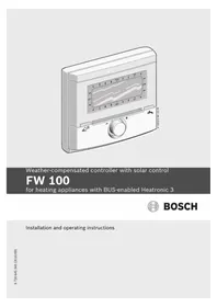
- FW
- OVERVIEW OF CONTROLS AND SYMBOLS
- CONTENTS
- EXPLANATION OF SYMBOLS AND SAFETY INFORMATION
- INFORMATION ABOUT THE APPLIANCE
- INSTALLATION (FOR INSTALLERS ONLY)
- COMMISSIONING (INSTALLERS ONLY)
- OPERATION
- MAIN MENU SETTINGS
- VIEWING INFORMATION
- MENU SETTINGS INSTALLER SETTINGS (FOR INSTALLERS ONLY)
- TROUBLESHOOTING
- ENERGY SAVING TIPS
- ENVIRONMENTAL PROTECTION
- COMMISSIONING LOG FOR THE HEATING SYSTEM
- INDIVIDUAL TIMER PROGRAM SETTINGS
- GUIDE TO INSTRUCTIONS
- IF YOU
- EXPLANATION OF SYMBOLS
- WARNINGS
- IMPORTANT INFORMATION
- ADDITIONAL SYMBOLS
- SYMBOL MEANING
- CONVENTIONS USED IN THESE INSTRUCTIONS FOR REPRESENTING THE MENU STRUCTURE
- SAFETY INSTRUCTIONS
- TECHNICAL SPECIFICATIONS 2.3 CLEANING
- SUPPLEMENTARY ACCESSORIES
- INSTALLATION EXAMPLE
- INSTALLATION
- INSTALLATION IN BOILER
- WALL MOUNTING
- INSTALLATION (FOR INSTALLERS ONLY) US/CA
- MOUNTING OF THE OUTDOOR TEMPERATURE SENSOR
- MOUNTING OTHER ACCESSORIES
- DISPOSAL
- MAKING THE ELECTRICAL CONNECTIONS
- ELECTRICAL CONNECTION IN BOILER
- ELECTRICAL CONNECTION TO WALL
- INTRODUCTION
- HEATING AND DHW PROGRAMS
- GENERAL INFORMATION
- WEEKLY PROGRAMS
- STRUCTURE OF PROGRAMS
- HEATING PROGRAMS
- DHW PROGRAMS
- RECIRCULATION PROGRAM
- SETTING PROGRAMS
- VIEWING ON THE DISPLAY AND NAVIGATING THROUGH THE MENU
- SETTING AND CHANGING SWITCH POINTS AND OPERATING MODES
- CHANGING (MOVING OR DELETING) A SINGLE SWITCH POINT
- USING GROUPS OF DAYS WHEN PROGRAMMING
- COPYING READY-MADE PROGRAMS
- RESETTING AN ENTIRE PROGRAM (REPLACING WITH FACTORY SETTINGS)
- RESETTING ALL SETTINGS (FOR INSTALLERS ONLY)
- MANUAL SETTING OF OPERATING MODES
- SELECTING THE OPERATING MODE FOR HEATING
- AUTOMATIC (FACTORY SETTING)
- CONSTANT HEATING
- CONSTANT ECONOMY
- CONSTANT FROST PROTECTION
- CHANGING HEATING MODE BEFORE THE PROGRAMMED TIME (BRINGING FORWARD THE NEXT SWITCH POINT)
- CHANGING THE DOMESTIC HOT WATER OPERATING MODE (TIME-LIMITED)
- VACATION MODE
- CHANGING THE SPECIFIED ROOM TEMPERATURE
- PERMANENTLY CHANGING THE SPECIFIED ROOM TEMPERATURE
- CHANGING THE SPECIFIED ROOM TEMPERATURE FOR A LIMITED PERIOD
- MAIN MENU SUMMARY AND SETTINGS
- HEATING PROGRAM
- MAIN MENU: HEATING
- TIMER PROGRAMS FOR HEATING
- MENU: HEATING > PROGRAM
- MENU: HEATING > PROGRAM > ACTIVATE
- MENU: HEATING > PROGRAM > EDIT
- MENU: HEATING > PROGRAM > EDIT > A:PROGRAM A ... F:PROGRAM F
- MENU: HEATING > PROGRAM > EDIT > A:PROGRAM A ... F:PROGRAM F > ALL DAYS
- MENU: HEATING > PROGRAM > EDIT > A:PROGRAM A ... F:PROGRAM F > MON - FRI
- MENU: HEATING > PROGRAM > EDIT > A:PROGRAM A ... F:PROGRAM F > SAT + SUN
- MENU: HEATING > PROGRAM > EDIT > A:PROGRAM A ... F:PROGRAM F > MONDAY, TUESDAY... SUNDAY
- MENU: HEATING > PROGRAM > VIEW
- TEMPERATURE LEVELS FOR OPERATING MODES AND HEATING RATE
- MENU: HEATING > PARAMETER
- MENU: HEATING > PARAMETER > HEATING CIRCUIT
- MENU: HEATING > PARAMETER > HEATING CIRCUIT > HEATING LEVELS
- DHW PROGRAM
- MAIN MENU: DOMESTIC HOT WATER
- WITH COMBI BOILER
- WITH HOT WATER TANK
- COMFORT
- SEPARATE PROGRAMS (INDEPENDENT TIMER PROGRAMS)
- DHW PROGRAM OPERATING MODES
- TIMER PROGRAM FOR DOMESTIC HOT WATER WITH COMBI BOILER
- MENU: DOMESTIC HOT WATER > DHW PROGRAM
- MENU: DOMESTIC HOT WATER > DHW PROGRAM > EDIT
- MENU: DOMESTIC HOT WATER > DHW PROGRAM > EDIT > ALL DAYS
- MENU: DOMESTIC HOT WATER > DHW PROGRAM > EDIT > MON - FRI
- MENU: DOMESTIC HOT WATER > DHW PROGRAM > EDIT > SAT + SUN
- MENU: DOMESTIC HOT WATER > DHW PROGRAM > EDIT > MONDAY, TUESDAY... SUNDAY
- MENU: DOMESTIC HOT WATER > DHW PROGRAM > VIEW
- TIME/TEMPERATURE LEVEL PROGRAM FOR DOMESTIC HOT WATER VIA TANK
- TIMER PROGRAM FOR DHW RECIRCULATION PUMP (SYSTEMS WITH DOMESTIC HOT WATER TANK ONLY)
- MENU: DOMESTIC HOT WATER > DHW RECIRC PUMP PROG > EDIT > ALL DAYS
- MENU: DOMESTIC HOT WATER > DHW RECIRC PUMP PROG > EDIT > MON - FRI
- MENU: DOMESTIC HOT WATER > DHW RECIRC PUMP PROG > EDIT > SAT + SUN
- MENU: DOMESTIC HOT WATER > DHW RECIRC PUMP PROG > EDIT > MONDAY, TUESDAY... SUNDAY
- MENU: DOMESTIC HOT WATER > DHW RECIRC PUMP PROG > VIEW
- PARAMETERS FOR DOMESTIC HOT WATER
- THERMAL DISINFECTION OF DOMESTIC HOT WATER
- MENU: DOMESTIC HOT WATER > THERMAL DISINFECTION
- OPERATING MODE
- OPERATING STATUS
- GENERAL SETTINGS
- TIME, DATE
- MENU: GENERAL SETTINGS > TIME AND DATE
- DISPLAY FORMATS
- MENU: GENERAL SETTINGS > DISPLAY FORMAT
- KEY LOCK
- LANGUAGE
- SOLAR SETTINGS
- MAIN MENU: SOLAR
- LIMITING TANK TEMPERATURE(S)
- SOLAR OPTIMIZATION
- MENU INFO
- INFO MENU OVERVIEW
- INSTALLER SETTINGS MENU SUMMARY AND SETTINGS
- INSTALLER SETTINGS: FAULT HISTORY
- INSTALLER SETTINGS: CUST SERVICE ADDRESS
- CONFIGURING THE HEATING SYSTEM
- INSTALLER SETTINGS: SYSTEM CONFIGURATION
- PARAMETERS FOR HEATING
- INSTALLER SETTINGS: HEATING PARAMETERS
- PARAMETERS FOR THE ENTIRE HEATING SYSTEM
- HEATING CIRCUIT PARAMETERS
- MENU: HEATING PARAMETERS > HEATING CIRCUIT 1 ... HEATING CIRCUIT
- CONFIGURING THE SOLAR THERMAL SYSTEM
- INSTALLER SETTINGS: SOLAR SYSTEM CONFIG
- PARAMETERS FOR SOLAR THERMAL SYSTEM
- INSTALLER SETTINGS: SOLAR SYS PARAMETERS
- COMMISSIONING THE SOLAR THERMAL SYSTEM
- RESETTING PARAMETERS FOR SOLAR THERMAL SYSTEM
- PARAMETERS FOR THE STANDARD SOLAR THERMAL SYSTEM
- MENU: SOLAR SYS PARAMETERS > 1. STANDARD SYSTEM
- PARAMETERS FOR SOLAR HEATING BOOST SYSTEM
- MENU: SOLAR SYS PARAMETERS > 2. HEATING SUPPORT
- PARAMETERS FOR THE SECOND COLLECTOR FIELD
- MENU: SOLAR SYS PARAMETERS > A COLLECTOR FIELD
- PARAMETERS FOR THE SOLAR RECHARGE SYSTEM
- MENU: SOLAR SYS PARAMETERS > B RELOAD SYS
- PARAMETERS FOR A HIGH/LOW PRIORITY SYSTEM
- MENU: SOLAR SYS PARAMETERS > C HIGH/LOW PRIORITY
- PARAMETERS FOR AN EXTERNAL HEAT EXCHANGER
- MENU: SOLAR SYS PARAMETERS > D EXT HEAT EXCHANGER
- PARAMETERS FOR THERMAL DISINFECTION
- MENU: SOLAR SYS PARAMETERS > E THERM DISINFECTION
- PARAMETERS FOR SOLAR OPTIMIZATION
- MENU: SOLAR SYS PARAMETERS > SOLAR OPTIMIZATION
- FAULT HISTORY
- VIEWING AND ENTERING THE CUSTOMER SERVICE ADDRESS
- INSTALLER SETTINGS: CUSTOMER SERVICE ADDRESS
- VIEWING SYSTEM INFORMATION
- INSTALLER SETTINGS: SYSTEM INFO
- SLAB DRYING FUNCTION
- INSTALLER SETTINGS: SLAB DRYING
- MENU: SLAB DRYING
- TOTAL SLAB DRYING TIME
- D 1 DAY
- TEST OF THE ACTUATORS ON THE SYSTEM
- INSTALLER SETTINGS: OUTPUT TEST
- TROUBLESHOOTING WITH DISPLAY
- TROUBLESHOOTING WITHOUT USING DISPLAY
- APPLIANCE DETAILS
- PACKAGING
- OLD APPLIANCES
- HEATING PROGRAM FOR HEATING CIRCUIT 1 AND HEATING CIRCUIT
- DHW CIRCULATION PROGRAM
- INDEX
- A
- B
- C
- D
- E
- F
- G
- H
- K
- L
- M
- N
- OPTION
- P
- PROGRAMMING
- R
- S
- T
- V
- W
- NOTES
- UNITED STATES AND CANADA
Brand : BOSCH
Model : FW 200
Category : Thermostat