GM-5400T - Audio Amplifier PIONEER - Free user manual and instructions
Find the device manual for free GM-5400T PIONEER in PDF.

| Product type | 2-channel audio amplifier |
| Brand | PIONEER |
| Model | GM-5400T |
| Power supply voltage | 14.4 V DC (10.8 V to 15.1 V acceptable) |
| Grounding | Negative pole |
| Power consumption | 30 A (4 Ω continuous supply) |
| Average current draw | 10 A (4 Ω for two channels) / 19 A (4 Ω for one channel) |
| Fuse | 30 A × 2 |
| Dimensions (W × H × D) | 265 mm × 62 mm × 346 mm |
| Weight | 3.8 kg (wiring cables not included) |
| Maximum output power | 250 W × 2 (4 Ω) / 760 W × 1 (4 Ω) |
| Continuous output power | 125 W × 2 (4 Ω, 14.4 V, 20 Hz-20 kHz, 0.2% THD) 380 W × 1 (4 Ω, 14.4 V, 20 Hz-20 kHz, 0.8% THD) 190 W × 2 (2 Ω, 14.4 V, 20 Hz-20 kHz, 0.8% THD) |
| Load impedance | 4 Ω (2 Ω to 8 Ω acceptable) Bridged connection: 4 Ω to 8 Ω acceptable |
| Frequency response | 10 Hz to 50 kHz (+0 dB, -1 dB) |
| Signal-to-noise ratio | 95 dB (IEC-A network) |
| Distortion | 0.03% (10 W, 1 kHz) |
| Separation | 70 dB (1 kHz) |
| Low-pass filter | Cutoff frequency: 80 Hz Slope: -12 dB/octave |
| Bass boost | Frequency: 50 Hz Levels: 0 dB, 6 dB, 12 dB |
| Gain control | RCA: 200 mV to 6.5 V Speaker: 0.8 V to 26 V |
| Maximum input level / impedance | RCA: 6.5 V / 22 kΩ Speaker: 26 V / 90 kΩ |
| Main functions | Bridged mode, low-pass filter, bass boost, power indicator, BFC switch (beat frequency control) |
| Safety | Overload, short circuit, and excessive temperature protection. Disconnect the negative battery terminal before installation. Use a fuse that meets specifications. |
| Installation | Requires battery wire and ground wire RD-223 (sold separately). Secure wiring with cable ties or adhesive tape. Do not cover the amplifier. |
Frequently Asked Questions - GM-5400T PIONEER
User questions about GM-5400T PIONEER
0 question about this device. Answer the ones you know or ask your own.
Ask a new question about this device
Download the instructions for your Audio Amplifier in PDF format for free! Find your manual GM-5400T - PIONEER and take your electronic device back in hand. On this page are published all the documents necessary for the use of your device. GM-5400T by PIONEER.
USER MANUAL GM-5400T PIONEER
BRIDGEABLE TWO-CHANNEL POWER AMPLIFIER
PykoBoDCTBO NOIb3OBaTeJia
Thank you for purchasing this PIONEER product.
Please read through this manual before using the product for the first time, to ensure proper use. After reading, please keep the manual in a safe and accessible place for future reference.
01 Before you start
Visit our website 3
In case of trouble 3
Before connecting/installing the amplifier 3
02 Setting the Unit
What's what 5
Setting gain properly 5
03 Connecting the units
Connection diagram 7
Before connecting the amplifier 7
About bridged mode 8
About suitable specification of speaker 8
Connecting the speakers 8
Connections when using the speaker input wire 9
Connecting the power terminal 9
Connecting the speaker output terminals 10
04 Installation
Before installing the amplifier 12
Example of installation on the floor mat or chassis 12
Additional information
Specifications 13

If you want to dispose this product, do not mix it with general household waste. There is a separate collection system for used electronic products in accordance with legislation that requires proper treatment, recovery and recycling.
Private households in the member states of the EU, in Switzerland and Norway may return their used electronic products free of charge to designated collection facilities or to a retailer (if you purchase a similar new one). For countries not mentioned above, please contact your local authorities for the correct method of disposal.
By doing so you will ensure that your disposed product undergoes the necessary treatment, recovery and recycling and thus prevent potential negative effects on the environment and human health.
Visit our website
Visit us at the following site:
http://www.pioneer.co.uk
- Register your product. We will keep the details of your purchase on file to help you refer to this information in the event of an insurance claim such as loss or theft.
We offer the latest information about Pioneer Corporation on our website.
In case of trouble
Should this product fail to operate properly, contact your dealer or nearest authorized Pioneer Service Station.
Before connecting/ installing the amplifier
WARNING
- The use of a special red battery and ground wire RD-223, available separately, is recommended. Connect the battery wire directly to the car battery positive terminal and the ground wire to the car body.
- This unit is for vehicles with a 12 V battery and negative grounding. Before installing in recreational vehicles, trucks or buses, check the battery voltage.
Always use a fuse of the rating prescribed. The use of an improper fuse could result in overheating and smoke, damage to the product and injury, including burns. - Check the connections of the power supply and speakers if the fuse of the separately sold battery wire or the amplifier fuse blows. Determine and resolve the cause, then replace the fuse with identical equivalent.
- Do not allow this unit to come into contact with liquids. Electrical shock could result. Also, damage to this unit, smoke, and overheating could result from contact with liquids. The surfaces of the amplifier and any attached speakers may also heat up and cause minor burns.
- In the event of any abnormality, the power supply to the amplifier is cut off to prevent equipment malfunction. If this occurs, switch the system power OFF and check the power supply and speaker connections. If you are unable to determine the cause, please contact your dealer.
Always disconnect the negative terminal of the battery beforehand to avoid the risk of electric shock or short circuit during installation.

CAUTION
Always keep the volume low enough so that you can hear sounds from outside the vehicle.
- Extended use of the car stereo while the engine is at rest or idling may exhaust the battery.
What's what
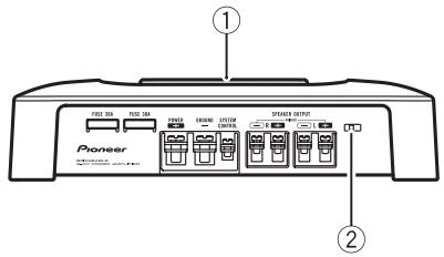
Front side
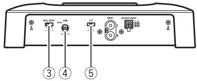
Rear side
To adjust the switch, use a flathead screwdriver if needed.
① Power indicator
The power indicator lights up to indicate power ON.
② BFC (beat frequency control) switch
Located front side the unit. If beats are audible while listening to MW/LW broadcasts via car stereo, change the BFC switch using a small flathead screwdriver.
BASS BOOST (bass boost level control) switch
You can select a bass boost level from 0 dB, 6 dB and 12 dB.
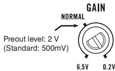
④ GAIN (gain) control
If output remains low, even when the car stereo volume is turned up, turn controls to lower level. If distortion occurs when the car stereo volume is turned up, turn these controls to higher level.
- For use with an RCA equipped car stereo (standard output of 500mV ), set to the
NORMAL position. For use with an RCA equipped Pioneer car stereo, with max. output of 4 V or more, adjust level to match that of the car stereo output.
- If you hear too much noise when using the speaker input terminals, turn the gain control to higher level.
LPF (low-pass filter) switch
Switch the settings based on the connected speaker.
- When the Subwoofer is connected: Select ON. This eliminates high range frequency and outputs low range frequency.
- When the full range speaker is connected: Select OFF. OFF outputs the entire frequency range.
Setting gain properly
- Protective function included to prevent malfunction of the unit and/or speakers due to excessive output, improper use or improper connection.
- When outputting high volume sound etc., this function cuts off the output for a few seconds as a normal function, but output is restored when the volume of the head unit is turned down.
- A cut in sound output may indicate improper setting of the gain control. To ensure continuous sound output with the head unit at a high volume, set amplifier gain control to a level appropriate for the preout maximum output level of the head unit, so that volume can remain unchanged and to control excess output.
- Despite correct volume and gain settings, the unit sound still cuts out periodically. In such cases, please contact the nearest authorized Pioneer Service Station.
Gain control of this unit
Above illustration shows NORMAL gain setting.
Relationship between amplifier gain and head unit output power
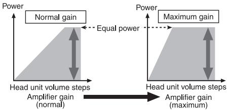
If amplifier gain is raised improperly, this will simply increase distortion, with little increase in power.
Signal waveform when outputting at high volume using amplifier gain control
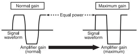
Signal waveform distorted with high output, if you raise the gain of the amplifier the power changes only slightly.
Connection diagram
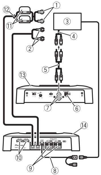
① Special red battery wire RD-223 (sold separately)
After completing all other amplifier connections, finally connect the battery wire terminal of the amplifier to the positive () battery terminal.
② Ground wire (Black)
RD-223 (sold separately)
Connect to metal body or chassis.
③ Car stereo with RCA output jacks (sold separately)
④ External output
⑤ Connecting wire with RCA pin plugs (sold separately)
⑥ Speaker input terminal
Please see the following section for speaker connection instructions. Refer to Connections when using the speaker input wire on page 9.
⑦ RCA input jack
⑧ System remote control wire (sold separately)
Connect male terminal of this wire to the system remote control terminal of the car stereo (SYSTEM REMOTE CONTROL). The female terminal can be connected to the auto-antenna relay control terminal. If the car stereo lacks a system remote control terminal, connect the male terminal to the power terminal via the ignition switch.
⑨ Speaker output terminals
Please see the following section for speaker connection instructions. Refer to Connections when using the speaker input wire on page 9.
10 Fuse (30A)× 2
⑪ Fuse (30A)× 2
⑫ Grommet
(13) Rear side
14 Front side
Before connecting the amplifier
WARNING
- Secure the wiring with cable clamps or adhesive tape. To protect the wiring, wrap sections in contact with metal parts in adhesive tape.
- Never cut the insulation of the power supply to feed power to other equipment. Current capacity of the wire is limited.
CAUTION
- Never shorten any wires, the protection circuit may malfunction.
- Never ground speaker wire directly or band together multiple speakers' negative () lead wires.
- If the system remote control wire of the amplifier is connected to the power terminal via the ignition switch (12 V DC), the amplifier will remain on with the ignition whether the car stereo is on or off, which may exhaust battery if the engine is at rest or idling.
Connecting the units
Install and route the separately sold battery wire as far as possible from the speaker wires. Install and route the separately sold battery wire, ground wire, speaker wires and the amplifier as far away as possible from the antenna, antenna cable and tuner.
About bridged mode
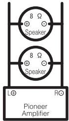
Diagram A - Proper
4Ω Bridged Mode
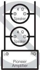
Diagram B - Improper
2Ω Bridged Mode
Speaker impedance is max. 4 please carefully check. Improper connection to the amplifier may result in malfunction or personal injury due to burns from overheating.
For bridged mode for a two-channel amplifier, with a 4 load, either wire two 8 speakers in parallel, Left and Right (Diagram A) or use a single 4 speaker. For other amplifiers, please follow the speaker output connection diagram for bridging shown on rear: two 8 speakers in parallel for a 4 load or a single 4 speaker per channel.
For any further enquiries, contact your local authorized Pioneer dealer or customer service.
About suitable specification of speaker
Ensure speakers conform to the following standards, otherwise there is a risk of fire, smoke or damage. Speaker impedance is 2
to 8 for stereo connection, or 4 to 8 for monaural and other bridge connection.
Subwoofer
| Speaker channel | Power |
| Two-channel output | Nominal input: Min. 135 W |
| One-channel output | Nominal input: Min. 420 W |
Other than subwoofer
| Speaker channel | Power |
| Two-channel output | MAX input: Min. 250 W |
| One-channel output | MAX input: Min. 760 W |

Connecting the speakers
The speaker output mode can be two-channel (stereo) or one-channel (mono). Connect the speaker leads to suit the mode according to the figures shown below.
Two-channel output (Stereo)
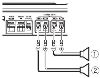
① Speaker (Left)
② Speaker (Right)
Connecting the units
One-channel output
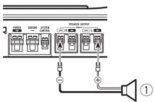
① Speaker (Mono)
Connections when using the speaker input wire
Connect the car stereo speaker output wires to the amplifier using the supplied speaker input wire.
- Do not connect both the RCA input and the speaker input at the same time.
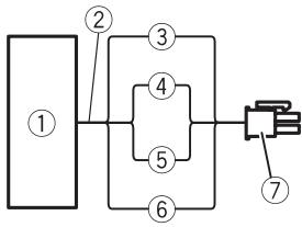
① Car Stereo
② Speaker output
③ Gray: Right
④ Gray/black: Right
⑤ White/black: Left
⑥ White: Left
⑦ Speaker input connector To speaker input terminal of this unit.
Connecting the power terminal
- The use of a special red battery and ground wire RD-223, available separately, is recommended. Connect the battery wire directly to the car battery positive terminal () and the ground wire to the car body.
WARNING
If the battery wire is not securely fixed to the terminal using the terminal screws, there is a risk of overheating, malfunction and injury, including minor burns.
1 Route battery wire from engine compartment to the vehicle interior.
After completing all other amplifier connections, finally connect the battery wire terminal of the amplifier to the positive () battery terminal.
① Positive () terminal
② Engine compartment
③ Vehicle interior
④ Fuse(30A)×2
⑤ Insert the O-ring rubber grommet into the vehicle body.
⑥ Drill a 14 mm hole into the vehicle body.
Connecting the units
2 Twist the battery wire, ground wire and system remote control wire.
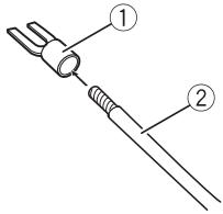
3 Attach lugs to wire ends. Lugs not supplied.
Use pliers, etc., to crimp lugs to wires.

① Lug
② Battery wire
③ Ground wire
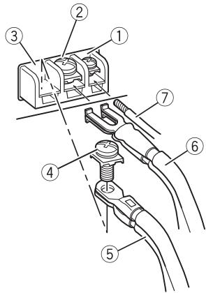
4 Connect the wires to the terminal.
Fix the wires securely with the terminal screws.

① System remote control terminal
② GND terminal
③ Power terminal
④ Terminal screws
⑤ Battery wire
⑥ Ground wire
⑦ System remote control wire
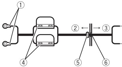
Connecting the speaker output terminals
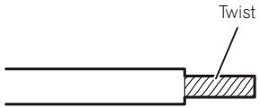
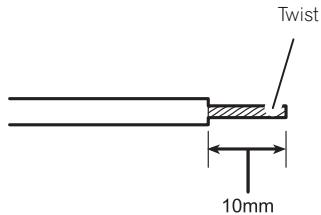
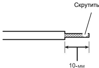
1 Expose the end of the speaker wires using nippers or a cutter by about 10mm and twist.
2 Attach lugs to speaker wire ends. Lugs not supplied.
Use pliers, etc., to crimp lugs to wires.
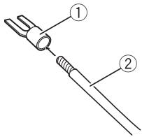
① Lug
② Speaker wire
3 Connect the speaker wires to the speaker output terminals.
Fix the speaker wires securely with the terminal screws.
Connecting the units
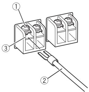
① Terminal screws
② Speaker wires
③ Speaker output terminals
Before installing the amplifier

WARNING
- To ensure proper installation, use the supplied parts in the manner specified. If any parts other than those supplied are used, they may damage internal parts of the amplifier, or become loose causing the amplifier to shut down.
- Do not install in:
Places where it could injure the driver or passengers if the vehicle stops suddenly.
Places where it may interfere with the driver, such as on the floor in front of the driver's seat.
- Install tapping screws in such a way that the screw tip does not touch any wire. This is important to prevent wires from being cut by vibration of the car, which can result in fire.
- Make sure that wires are not caught in the sliding mechanism of the seats, resulting in a short-circuit.
- When drilling to install the amplifier, always confirm no parts are behind the panel and protect all cables and important equipment (e.g. fuel/brake lines, wiring) from damage.

CAUTION
To ensure proper heat dissipation of the amplifier, ensure the following during installation:
- Allow adequate space above the amplifier for proper ventilation.
- Do not cover the amplifier with a floor mat or carpet.
- Avoid routing wires through hot areas, such as near the heater outlet. Heat may damage the insulation, resulting in a short-circuit through the vehicle body.
- The optimal installation location differs depending on the car model. Secure the amplifier at a sufficiently rigid location.
- Firstly make temporary connections and check to ensure the amplifier and system operate properly.
After installing the amplifier, confirm that the spare tire, jack and tools can be easily removed.
Example of installation on the floor mat or chassis
1 Place the amplifier in the desired installation location.
Insert the supplied tapping screws (4 mm × 18 mm) into the screw holes and push on the screws with a screwdriver so they make an imprint where the installation holes are to be located.
2 Drill 2.5mm diameter holes at the imprints either on the carpet or directly on the chassis.
3 Install the amplifier with the use of supplied tapping screws (4 mm × 18 mm).
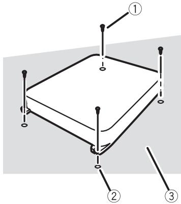
① Tapping-screws (4mm× 18mm)
② Drill a 2.5 ~mm diameter hole
③ Floor mat or chassis
Additional information
Specifications
Power source 14.4 V DC (10.8 V to 15.1 V allowable)
Grounding system Negative type
Current consumption 30 A (at continuous power, 4
Average current drawn 10 A (4 Ω for two channels)
19 A (4 Ω for one channel)
Fuse 30 A x 2
Dimensions (W× H× D) ...265 mm × 62 mm × 346 mm
Weight 3.8 kg (Leads for wiring not included)
Maximum power output ......... 250W× 2 (4) /760 W x 1 (4Ω)
Continuous power output ... 125W× 2 (at 14.4 V, 4 20 Hz to 20 kHz 0.2% THD) 380W× 1 (at 14.4 V, 4 20 Hz to 20 kHz 0.8% THD) 190W× 2 (at 14.4 V, 2 20 Hz to 20 kHz 0.8% THD)
Load impedance 4Ω (2Ω to 8Ω allowable)
(Bridge connection: 4Ω to 8Ω allowable)
Frequency response 10 Hz to 50 kHz (+0 dB, -1 dB)
Signal-to-noise ratio 95 dB (IEC-A network)
Distortion . 0.03% (10 W, 1 kHz)
Separation 70 dB (1 kHz)
Low pass filter: Cut off frequency ..80 Hz Cut off slope .-12 dB/oc
Bass boost: Frequency 50 Hz Level 0 dB/6 dB/12 dB
Gain control: RCA 200 mV to 6.5 V Speaker 0.8 V to 26 V
Maximum input level / impedance: RCA 6.5 V/22 kΩ Speaker 26 V/90 kΩ

Notes
- Specifications and the design are subject to modifications without notice due to improvements.
- The average current drawn is nearly the maximum current drawn by this unit when an audio signal is input. Use this value when
working out total current drawn by multiple power amplifiers.
④ Commande GAIN (gain)
Dimensioni (L x A x P) ......265 mm x 62 mm x 346 mm
Deverstkingsfactor (gain) instellen 69
⑤ LPF-schakelaar (low pass filter)
Deversterkingsfactor (gain)instellen
250 W × 2 (4 Ω) / 760 W × 1
(4Ω)
Ipepe yctahOBKOYcINNTeJI 90

m = 311 ;
EcnBbJxenaTe yTnIIN3NpOBaTb DaHNoe
n3dJIne, He BbIbpaCbIbAaTe erO BMeCTe C
o6bIyHbIM bItobBbIM MycOpom. CyuecTByeT
OTdJIbHaay CnCTema C6opa NcIOnIb30BaHHbIX
3JIeKTPoHHbIX n3dJIIn B COOTBeTCTBnC 3a-
KOHOaTeNbCTBOM, KOTOPa IpeDnOlaRaET COOTBeTCTByUouee o6paUeHne, Bo3Bpat n
nepepa6OtKy.
YacThbIe IInuBa C tpaHax EbpocOIO3a, UBei- cApnN HOpBernn MOryt 6ecPnAtho Bo3Bpa- uTaTb NcIOnIb3OBaHbIe 3JIeKTPoHHbIe
13JeIIBA C nEuaIIN3IpOBaHbIe PnyKtbl
Ipiema IN B MaRa3IN (pN pOKyIKe aHaNo- rHOrO HOBOr yCTpoICTBa).
Ecni Ba7a cTpaHa He yka3aHa B npBedeHnOM BblIe nepeYe, o6paauTebc B oprAhbI MeCTHO ynpaBLeHnna 3a INHcTpyKzmaMn IOp npabInbHoYtINN3aCnI pOdykTa.
Tem cambIM Bby oobcepeHTe yTnH3aunio BaWero n3dennr c co6nIOJeHHem o6raTeIb- HbIX npOeUp no 6pa60Te, yTnH3aunu IN BTOPNHOr nepepa60Te K, TAKM O6pa3OM, IpeoTbPaTIte NOTeHuaJIbHOe HeraTINBHOe BO3DeiCTBne Ha OKpykaIoUyU CpeDu Y 3DopOBBe JIODeE.
Pocetnte haaw caT
Iocetnte haw caT:
http://www.pioneer-rus.ru
3aperncnpyntpno6peHnoe n3dene. Mbl coxpanm CbeDEnn o BaSei noKynke, yTO pOnoxet Bam ccbIaTbcra Ha 3Ty INfOpMaunIO B cnyae ctpaxoBOrO Tpe6obAnHn IO npuHne notepn nn KpaKn.
- Camyio CBexyIO INHΦopMaζIIO O Pioneer Corporation MOxHO NpIyUHTb Ha Hauεm Be6-caITe.
B Clyuae BO3HnKHOBeHnHaHeNoJaOk
PnB BKJIOUeHIN NITaHIN 3aRopaETcN INdKATOP NITaHIN.
② PeryIaTOp BFC (uactOtbl 6neHn)
PacnoIoxen Ha nepeDnei naHei ycTpoIcTaBa.EcnPiBn BocnpOn3BeDeHn TpaHCJIaun C4/HU dnaNa3oHOB B pexImeCTepeo CbluHbI 6NeHnI, n3MeHnteNoIIOxHHe peYrJATopa BFC c NOMOu bO tBeptKc nllockm JkaIOM.
③ PeruJrTop BASS BOOST (ypoBeHb ycnJIeHn Hn3Knx YacToT)
C nOMOuBIO peryIaTopa MoXHO BbIbpaTb OdIN H3 cIeNyUoIuX yPobHeN Hn3Knx Ya-ctOT: 0 d5, 6 d5 n 12 d5.
④ PeryIaTOp GAIN (ypOBHry yCnJIeHNJ)
EcnBbIXoHnaMoUHocTbOCTaETcHn3-Ko,JaKe KOrdapeRyIaTOp rPOMKoCTN 3Byka HaxoDITcB MaKcMmaIbHOM NO
JIOXeHN, yCTaHOBnTe peRyIaTOpbl MOUHOcTn Ha 6OJIe Hn3Km IyPOBeHb. EcIn npi YCTaHOBKe peRyIaTOpora rPOMKOCTn B MaKcMJaBHoE NOLOXeHne NOBnIOTcN ICKaKeHn, yCTaHOBnTe peRyIaTOpbl MOUHOCTn Ha 6OJIe BbICOKn IyPOBeHb.
- Пи IncNoJIb3OBAHn ABTomO6nJIbHOy aydnoCnCTembl, OchauSeHHoR RCA (ctaHdapTHaB bIXODHaMoUHocTb 500 MB), yctahOBIne peRyIaTOp B noIOKeHne NORMAL. Пи IncNoJIb3OBAHn ABTomO6nJIbHOy ayduNOCnCTembl Pioneer, ochaueHHoR RCA, c bIXoHDHm MoUHoCTbH 4 B n 6oJee ycTaHOBIne ypoBeHb MOUHocTN yCNIInTeTaN TAK, YTObbl OH COOTBETCTBOBaN yPOBnIO BbIXODHOu MoUHocTN aBTOMO6nJIbHOH ayDINOcNCTembl.
- Ecni npi nCIOJIb3OBAHnB XOДнbIX pa3-bEMOB DIIЯ NOДКЛIOUChENI rPOMKOrOBOpIteNcblIshNbI ShMbI, yBeJIuHbTe ypoBeHb ycINeHnI.
⑤ PerylTop LPF (Фильтг Нзкх застот)
IpeekJIIOUHTe HAcTPOKIN B COOTBETCTBM C XapaKTePcNCTIKaMNI OJKNIOUeHHOTo rPOMKOROBOpNTeI.
- Ppi nodknIOueHm ca6Bypepa:
Bb6epnte ON. PnI 3tOM OTCEKAOTc BbICOKNE YACTOTbl N BOCPON3BOJATCR HN3KNE YACTOTbl. - Пи подключенишироконлочогorpoMKOROBOPHTEL:
YcTaHOBnTe NepeKnIOuATEb B NoIOXeHne OFF. Pn yCtAHOBKe nepeKnIOuATEJIa B NoIOXeHne OFF BOCnPON3BOUHTcB BECb DnIaNa3OH YAcTOT.
YCTAHOBka KO3ΦΦnCneHTa YCSJIeHnA
BycpoCTBe npedymTopeHa yHKzna 3aunTbI OT yctaHOBKn CnUkOM BbcOKoM OuHOCTN, HeBepHoro NcNoJIb3OBAHn IIN HeBepHoro NpokNIOHeHn, cnoocbHex npnbEcTN K BbIXOy ycuiNTeJr n3 CTPOR.
- Пиу установке слшков ВьсOKОу уровья Гомкости и.T.п.даная Функця на Heckолько Секунд OTКПЮает 3BYK (ЗTO HeЯВяяETСЕнCSРавHOCtю) и BHOБВ BKПЮает erо при снжжени уровья ГомкOSTи на ГЛавНOM yCTpoiCTBE.
- OTKJIIOUeHHe 3Byka MoKet O3HaayaTb, YTO yCTaHOBJIeH HeBepHbI KO3ΦΦnIeHT ycIIeHnry. YTO6bl 3Byk He OTKIIOuAJIcR npu yCTaHOBKe MaKcIMaJIbHOrO yPOBnRA rPOMKOCTn Ha OCHOBHOM yCTpOJCTBe, KO3ΦΦnIeHT ycIIeHnry ycINITeRЯ DOJIKeH COOTBETCTBOBaT MaKcIMaJIbHOMy yPOBHIO BbIXoHDm MOIHCToN OCHOBHOY cTPOJCTBa.B 3tOM Cnyuae yPOBeHb rPOMKOCTn He 6yDet n3MeHrTaCBA, a KO3ΦΦnIeHT ycIIeHnry He 6yDet npeBbIwaTb DONYCTMIMO 3HaueHnra.
- UpoBHeI rPOMKocTn I KO3ΦΦuNMeHT yCINJIeHnY yCTaHOBJIeHbI IpaBnIbHO, HO 3ByK BCE paBHO IepNoDiUneCKn OTKnIOHaETcR. B 3tOM cIyuae O6paTntEcB B 6nJaI Shn aBTOpN3OBaHHbI cepBnCHbI pNHT Pioneer.
Perylnpobka Ko3ΦnueHt a ychneHna daHHoro yctpoiCTBa
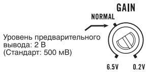
Ha pncyHke BblIe NOKa3aHo NnONoXeHne perynToppa ycInHeNHa yPobHe NORMAL.
OTHOSeHHe KO3ΦΦnIeHtA yCnJIeHnY CYNJIInTeJI N BbIXoHoi MOUHOCTN OCHOBHorO yCTpoiCTBa

ПричрзмернOM NOВышении KOЗФпциЕн Та усilеня pe3KO yBeINuHBAIOTc ИСКаж- н,在a MОSUHOCTb NOБИSaETc He3HaHTeJIbHo.
ΦopMa CnrgHana Ha BbIXoGe npn BbICOKOM ypOBHe rPOMKoCTn, CO3daHHOM C nOmoUbIOp peRyJIaTopa Ko3ΦΦnUeHTa ycInJeHHy ycInNTeJIa
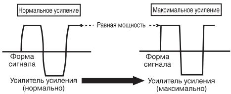
NcKaKeHHaФopMa CnHaHa npi BbICOKOM yPoBHe rPOMKoCTn.Пр nOBblIeHm NkOΦ-ФицHeNTa yCnJIeHMy yCnJIInTeJI MOnHOCt b N3MeHReTc Hc3HaHInTeJIbHo.
IopKJIIOUeHne yCTpoiCTB

Cxema nodkloucheHn
① CneuNbHbI KpaChbI npOBd nIy noDkHoueHnK aKKymyJrTOpy RD-223 (npno6peTaETcOtJeBHo) PocLe pOdkHoueHn BceX npOBoB yCInTeLa NocLeDNHM NpOKHOnTE npOBoD, NdyuNt OKJIeMMbl YcNInTeLa K NOJokHTbHO () KJIeMMe AKKymyJrTOpa
② Пювов заимлени (Черный) RD-223 (принобразаетс отдьно) Рожнисте К металлическов чакишсян.
③ ABTOMO6HbHaayDIOscIeMa C BbIXoHNbIMn IHe3dAmn IJaI NOkJIuOeHnKa6EJRA (Pnio6petaTe OTDJIbHO)
④ BHeuHnBbIXoD
⑤ CoeHnHTeJbHbI npOBc StKepeamRCA (npno6peTaetcraOTdJIbHO)
⑥ BxOJHoe rHe3do rPOMKOrOBOpnteIa HnCTpykUINIO NOIPOKJIoueHNIO rPOMKOrOBOpNTeIe CM.Bpa3dene, yKa3aHHOM HnKe. CM.IoKJIoueHnC nCnONb3ObaHnEm BXoJHOrO IpoBODa rPOMKOrOBOpNTeIHa cTp.86.
⑦ BxOJHoeIHe3oRCA
⑧ПювODДЯ NOДКЛQUECHENCиCTeMbIДИСТанцIOHHOунравLEня(пюбpeTaetcra OTdJIbHO) ПОДКЛQUCHITEшTEKEPньВБIBOДпювOAк pa3bemyCиCTeMbIДИСТанцIOHHOунравLEня abTOMOBINьнayaDIONCiTe-MоY(SYSTEM REMOTE CONTROL).ΓHe3doBOB bVBoD MOXHO NOДКЛQUCHITbKpa3bemypeIe ynpabLNeHЯ aHTEHOHayDIONCiTeMbI.EcIny aBTOMOBINbHoy aYDIONCiTeMbIOTcYcTcByET pa3bEmДЯ NOДКЛQUECHENCиCTeMbIДИСТанцIOHHOунравLEня,NOДКЛQUCHITEшTEKEPньВБIBOДКЛEMMe NITaHMyЧepe3ЗAMOK3aJNIRAHN.
⑨ BbIXoNDhBie KIeMMblIy IIOKIIoueHnI rIpOM-KorOBOpHTeNeI HNcTpkyuINNo IOKIIoueHnIO rPOMKOrOBOpHTeNeI cm.B pa3dene, yka3aHHOM HnKe. Cm.IoKIIoueHnC uCnONb3ObaHnEM BXoH-Horo npoBOda rPOMKOrOBOpHTeNa CTp.86.
10Плавскийпразадхарнтель(30A) × 2
⑪ Плавский п体现在халтейь (30 A) × 2
12 PtoxOHaHn30IpyUo7aBtUka
⑬ 3aJnJaHaHeIb
14 PerednnaHelb
Ipeed nodkloucheHnem ycnltela

PNEyPPEKDEHNE
3aKpeINTE npOBOda npn NOMOUs 3aXIMOB nIIN I3OJLcIOHNOJIeHTb.IYTo6bl 3aUNTbI npOBOkU, 3aI3OJNpyIte yUacTKn, COpNIkaCaHOUIeCEcC MTeAIIJIueCKMm YactrMM, C NOMOUsIOI3OJLcIOHNOHJIeHTbl.
He hapuataIte n3oJauIIO npOBoOB nITaHnIaIy IpaIINITaHnHa Ja pyroe o6OpydoBaHne. IpOBoDa IMeIoT orpaHnueHHy IO donyCTmMyIO Harpy3Ky NO TOky.

BHIMAHNE
3anpeaetcyaKopauBaTb npoBoa, cenb 3aunTb MOKeT BbIuN3 CTPOJ.
He npdklouaTe npOBoI rpoMkoROBOpnteHa HnocpeIcTBeHHO K 3a3eMnEHHIO He CBA3bIBaTe BmecTe HECKoJIbKO OTPuCaTeNbHbIX () BBIOOB npOBoOB rpoMkoROBOpnteJe.
- Ecni npOBoC nCTeMbI dNCTaHcUHOHHOrO ynpabJIeHnY ycINITeMe NODKNIuOHEN K KJIemme NiTaHnY uepe3 3AMOK 3aXJrHaHnY (12 B Noct. ToKa),To ycINITeBb dyET hXoDNTb C8 BV KJIIOUeHHOM COCToRHN Npi BVKJIIOUeH-NOM 3aXJrAHN BHE 3aBNCIMOCtN OT TORO, BKIOUeHa ABTOMO6InbHaaydIOscNTema IINI HET; 3TO MOKeT pINBecTn K pa3PraDke Ak-KymyIaTOPa,EcNI DBrIaTeB BbIKIOUeH INI pa6Otaet Ha XOIOCTbIX O6OpOTax.
- Пюложип e 3akpeniTe npno6peTaembl OТдьно пpoBOd ДЯ NOДКЛчЕня K akkyMулгОу Кк можно Дальш e OT ppoBOOВ rPOMKOROBOPHTeNeI.
ПролokNTe ИЗakpenITE пиобраземь OТДЕЛБНО ПЮВОД ДЯ NOДКПUCHENHA K AkkyMулТOPу,пюВОД 3a3eMLeHINЯ,пюВОД aTROMKOROBOPITeNeI N yCINITeJI KAK MOxHOnDAДЛБШЕ OT aHTeHHbl, Ka6eIЯ aHTeHHbl I TIOHEpa.
PexMM MocTOBOro CoeINHeHnA

CXMHa-A-PrpBnHBoe NDKQNQHHe
MocBoe coeHneHne 4 Ω

CxemhaB-HenpabvlnbHoe pndkHoHeMe
MocroBoe coeHneHne 2Ω
MaKcImaJIbHoe cOpOTnBJIeHne rPOMKOrOBOpNTeI He DoJNKe IpeBbIaTb 4 Ω. Y6eIITecb, yTO daHHe ycIOBne BbIOnHeNo. HeBePHO noDkJIIOUeHne ycINTeJI M0KET pINBecTu K erO NOBpeJDeHIO INI K TpaBMam B BVNe OxKOrOB, BbI3BaHHbIX NpeERpeBOM.
MocToboe coeDInHeHne DByXkaHaIbHorO yCnIInTe n C harpy3ko4 0 npedctabIaETco6oB npapAnIbHoe noKKnIOHe H DByx rPOMKOROBOpNTe n C conpoTnBHeHem 8 O KaKdbI, IeBOrO n npaboro (CxemaA), IIn6oOnHO rPOMKOROBOpNTe n C conpoTnBHeHem 4 O.ДЯ npdynx ycNITe n Cm.Cxemy MocTOBOrno NOkKnOChE hraPOMKOROBOpNTe n Ha 3aJHe nPaHEn: Dba rPOMKOROBOpNTe n C conpoTnBHeHem 8 O, NoKKnOChEHHbIX npapAnJIbHo, DnHarpy3kn 4 O, IIn6oOnn rPOMKOROBOpNTe b C conpoTnBHeHem 4 O Ha KaKdbI KaHaI.
4 PoiKJIIOHHTe npoBOda K KJIEMMaM.
Плnotно зakpenite побова на КнемMax спомоцью ВИNTOB.
① Knemma CnCTembl DnctaHNoHHOrO ynpabNeHn
② KJemma 3a3eMJIeHnGND
③ KneMMA nHTaHn
④ KJIeMMHbIe BNHTbl
⑤ Пювовдя подклоченя К akkyмлгTo- py
⑥ Побовд заemonюня
⑦ ПобовсnteMbI ДИСТаHCUOHHOупавлeneria
ПОДКЛЮЧЕни пюворов К БыхоньIM КLEMМаM rgpOMKOrOBOPHTeJei
1 C nomoIbIy KcyaueK IIN peKyUeero HnCTpyMeHTA ONUCTNTE OT N3OJIaUN npIMepHO 10-MM yuaTOK npoBoDa n ckpyTnte erO.
2 HaedeHbTe HakoHeuHnKn Ha KOHcbl npoBODB rPOMKOROBOpNTeJIa. HakoHeuHKn B KOMNJIeKT NocTaBKN He BXOJrT.
C NOMOUIIIOCKORYB EINI aHJIOrNHO- IIOHCTpyMeHTa 3akpeIITe HAKOHeuHKn Ha npoBOdax.
① HakoHeuHnK
② Побовд ромкогор本质上
ПOTpe6PЯEMbI TOK 30A (pnpHOMHaJIbHOB BbIXOHOH MOUHOCn,4Ω)
CpeiHoe 3NaueHne Toka ...10A (4ΩДЯ DByX KaHa-nOB) 19A (4ΩДЯ OJHOro KaHa-na)
TpomkoorOBopntJIb.....26B/90KΩ
Приимechanical:
B coOTBcETCBn CO cTaTbe 5 3aKoHa PocCncko Fedepaun "O 3aunTe npab noTpebnte" n noCTaHOBnEHnEMnpaBnTeBCTBa PocCncko Fedepaun N720 ot 16.06.97 kOMPAnHr Pioneer Europe NV orOBApIBaet cIeDyUoJcI cPOK cLyXkbIu3JeNl, oΦuuaJIbHO NOCTABnREMbIX Ha pocCnckn pbHok.
AByTomobunbna 3neKtpoHnka:6IeT Dpyrue n3dennia (HayuHnKn, Mnkpofohbl n t.n.):5IeT

PpIMeuaHn
XapakTepeNtKnIKoHCTpyKUmaMOryT6bITbI3MeHeHbICeJIbIOxUYuUHeHna6e3PpeBapHTeJbHOrOYBeDOMHeHn.
CpeJhee 3NaHeHne TOKa 6nI3KO K MaKcIMaJIbHOMy 3HaHeHIO TOKa, NOTpe6JIeEMOMy DaHHbIM yCTPOINCTBOM, KOrga Ha BXoI NOdaETcaydIoNcIHnA.IcNoIb3yTe 3TO 3Na-ueHne npi nOcHteCymMapHOrTO Ka, NOTpe6JIeEMOrO HeckoJIbKIMn YcNJInTeJIaMm MOUHOCTn.
Данhoe yctpoICTBO npOIN3BedeHO B Manai3nn.
http://www.pioneer.eu
Visit www.pioneer.co.uk (or www.pioneer.eu) to register your product.
4-1, MEGURO 1-CHOME, MEGURO-KU
PIONEER ELECTRONICS (USA) INC.
P.O. Box 1540, Long Beach, California 90801-1540, U.S.A.
TEL: (800) 421-1404
PIONEER EUROPE NV
Haven 1087, Keetberglaan 1, B-9120 Melsele, Belgium
TEL: (0) 3/570.05.11
PIONEER ELECTRONICS ASIACENTRE PTE. LTD.
253 Alexandra Road, #04-01, Singapore 159936
TEL: 65-6472-7555
PIONEER ELECTRONICS AUSTRALIA PTY. LTD.
178-184 Boundary Road, Braeside, Victoria 3195, Australia
TEL: (03) 9586-6300
PIONEER ELECTRONICS OF CANADA, INC.
300 Allstate Parkway, Markham, Ontario L3R 0P2, Canada
TEL: 1-877-283-5901
TEL: 905-479-4411
PIONEER ELECTRONICS DE MEXICO, S.A. de C.V.
Blvd.Manuel Avila Camacho 138 10 piso
Col.Lomas de Chapultepec, Mexico, D.F. 11000
TEL: 55-9178-4270
先鋒股份有限公司
總公司:台北市中山北路二段44號13樓
電話:(02) 2521-3588
先鋒電子(香港)有限公司
香港九龍尖沙咀海港城世界商業中心
9樓901-6室
電話:(0852) 2848-6488
Published by Pioneer Corporation.
Copyright © 2008 by Pioneer Corporation.
All rights reserved.