
DJM-350 - DJ mixer PIONEER - Free user manual and instructions
Find the device manual for free DJM-350 PIONEER in PDF.



User questions about DJM-350 PIONEER
0 question about this device. Answer the ones you know or ask your own.
Ask a new question about this device
Download the instructions for your DJ mixer in PDF format for free! Find your manual DJM-350 - PIONEER and take your electronic device back in hand. On this page are published all the documents necessary for the use of your device. DJM-350 by PIONEER.
USER MANUAL DJM-350 PIONEER
The Pioneer website listed above provides answers to frequently asked questions, information about software, and other up-to-date data of assistance to our customers.
Operating Instructions
Mode d'emploi
Bedienungsanleitung
Thank you for buying this Pioneer product. Please read through these operating instructions so you will know how to operate your model properly. After you have finished reading the instructions, put them away in a safe place for future reference. In some countries or regions, the shape of the power plug and power outlet may sometimes differ from that shown in the explanatory drawings. However the method of connecting and operating the unit is the same.
IMPORTANT
The lightning flash with arrowhead symbol, within an equilateral triangle, is intended to alert the user to the presence of uninsulated “dangerous voltage” within the product’s enclosure that may be of sufficient magnitude to constitute a risk of electric shock to persons.
CAUTION
RISK OF ELECTRIC SHOCK DO NOT OPEN
CAUTION:
TO PREVENT THE RISK OF ELECTRIC SHOCK, DO NOT REMOVE COVER (OR BACK). NO USER-SERVICEABLE PARTS INSIDE. REFER SERVICING TO QUALIFIED SERVICE PERSONNEL.

The exclamation point within an equilateral triangle is intended to alert the user to the presence of important operating and maintenance (servicing) instructions in the literature accompanying the appliance.
D3-4-2-1-1_A1_En
Replacement and mounting of an AC plug on the power supply cord of this unit should be performed only by qualified service personnel.
IMPORTANT: THE MOULDED PLUG
This appliance is supplied with a moulded three pin mains plug for your safety and convenience. A 5 amp fuse is fitted in this plug. Should the fuse need to be replaced, please ensure that the replacement fuse has a rating of 5 amps and that it is approved by ASTA or BSI to BS1362.
Check for the ASTA mark ASA or the BSI mark 🏠 on the body of the fuse.
If the plug contains a removable fuse cover, you must ensure that it is refitted when the fuse is replaced. If you lose the fuse cover the plug must not be used until a replacement cover is obtained. A replacement fuse cover can be obtained from your local dealer.
If the fitted moulded plug is unsuitable for your socket outlet, then the fuse shall be removed and the plug cut off and disposed of safely. There is a danger of severe electrical shock if the cut off plug is inserted into any 13 amp socket.
If a new plug is to be fitted, please observe the wiring code as shown below. If in any doubt, please consult a qualified electrician.
IMPORTANT: The wires in this mains lead are coloured in accordance with the following code: Blue : Neutral Brown : Live
As the colours of the wires in the mains lead of this appliance may not correspond with the coloured markings identifying the terminals in your plug, proceed as follows;
The wire which is coloured BLUE must be connected to the terminal which is marked with the letter N or coloured BLACK. The wire which is coloured BROWN must be connected to the terminal which is marked with the letter L or coloured RED.
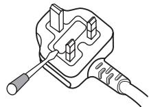
How to replace the fuse: Open the fuse compartment with a screwdriver and replace the fuse.
natural_image
Line drawing of a plug with a screwdriver inserted, no text or symbols presentD3-4-2-1-2-2*_A2_En

If you want to dispose this product, do not mix it with general household waste. There is a separate collection system for used electronic products in accordance with legislation that requires proper treatment, recovery and recycling.
Private households in the member states of the EU, in Switzerland and Norway may return their used electronic products free of charge to designated collection facilities or to a retailer (if you purchase a similar new one).
For countries not mentioned above, please contact your local authorities for the correct method of disposal.
By doing so you will ensure that your disposed product undergoes the necessary treatment, recovery and recycling and thus prevent potential negative effects on the environment and human health.
K058b_A1_En
WARNING
This equipment is not waterproof. To prevent a fire or shock hazard, do not place any container filled with liquid near this equipment (such as a vase or flower pot) or expose it to dripping, splashing, rain or moisture.
D3-4-2-1-3_A1_En
WARNING
Before plugging in for the first time, read the following section carefully.
The voltage of the available power supply differs according to country or region. Be sure that the power supply voltage of the area where this unit will be used meets the required voltage (e.g., 230 V or 120 V) written on the rear panel.
D3-4-2-1-4*_A1_En
WARNING
To prevent a fire hazard, do not place any naked flame sources (such as a lighted candle) on the equipment.
D3-4-2-1-7a_A1_En
WARNING
Slots and openings in the cabinet are provided for ventilation to ensure reliable operation of the product, and to protect it from overheating. To prevent fire hazard, the openings should never be blocked or covered with items (such as newspapers, table-cloths, curtains) or by operating the equipment on thick carpet or a bed.
D3-4-2-1-7b*_A1_En
Operating Environment
Operating environment temperature and humidity: +5 °C to +35 °C (+41 °F to +95 °F); less than 85 %RH (cooling vents not blocked)
Do not install this unit in a poorly ventilated area, or in locations exposed to high humidity or direct sunlight (or strong artificial light)
D3-4-2-1-7c*_A1_En
If the AC plug of this unit does not match the AC outlet you want to use, the plug must be removed and appropriate one fitted. Replacement and mounting of an AC plug on the power supply cord of this unit should be performed only by qualified service personnel. If connected to an AC outlet, the cut-off plug can cause severe electrical shock. Make sure it is properly disposed of after removal.
The equipment should be disconnected by removing the mains plug from the wall socket when left unused for a long period of time (for example, when on vacation).
D3-4-2-2-1a_A1_En
CAUTION
The ⏻ switch on this unit will not completely shut off all power from the AC outlet. Since the power cord serves as the main disconnect device for the unit, you will need to unplug it from the AC outlet to shut down all power. Therefore, make sure the unit has been installed so that the power cord can be easily unplugged from the AC outlet in case of an accident. To avoid fire hazard, the power cord should also be unplugged from the AC outlet when left unused for a long period of time (for example, when on vacation).
D3-4-2-2-2a*_A1_En
POWER-CORD CAUTION
Handle the power cord by the plug. Do not pull out the plug by tugging the cord and never touch the power cord when your hands are wet as this could cause a short circuit or electric shock. Do not place the unit, a piece of furniture, etc., on the power cord, or pinch the cord. Never make a knot in the cord or tie it with other cords. The power cords should be routed such that they are not likely to be stepped on. A damaged power cord can cause a fire or give you an electrical shock. Check the power cord once in a while. When you find it damaged, ask your nearest PIONEER authorized service center or your dealer for a replacement.
S002*_A1_En
How to read this manual
The names of displays, menus, and buttons in this manual are enclosed in brackets. (e.g. [MASTER] channel, [ON/OFF], [File] menu)
01 Before start
Features 5
System setup example....5
What's in the box....5
02 Connections
Names of terminals....6
Connecting the input/output terminals 7
03 Operations
Control panel 8
About the power switch of this unit....9
Basic operations (mixer section)....9
Monitoring the sound over headphones (headphones section) .....11
Using the effect function (master effect section) 11
Using a microphone or external device (MIC/AUX section) 11
Recording the performance (USB recording section) 12
About the auto standby function....12
04 Additional information
Troubleshooting 14
About errors....15
About USB devices/files usable on this unit 15
About the exemption clauses 16
Specifications....16
Before start
Features
This unit is a DJ mixer that carries over the technology of the Pioneer DJM series, the world standard in club sound. It is a standard type unit equipped with the basic functions required for mixing, enabling full-fledged DJ play easily.
USB recording
With this unit, the sound of DJ performances can easily be recorded on USB devices (portable flash memory devices, etc.). The recorded sound can also be played on this unit.
3-band equalizer
This unit is equipped with a 3-band equalizer allowing the volume of the high, medium and low frequency ranges to be adjusted separately. Not only can the tone be adjusted to your tastes, the sound for a certain range can be turned completely off by turning the control all the way counterclockwise (isolator function).
MASTER EFFECT (GATE, CRUSH, JET, FILTER)
This unit is equipped with four effect buttons allowing the sound to be changed in various ways. The mood of the sound can be modified easily, simply by pressing a button and turning the control.
MIC/AUX INPUT
This unit is equipped with a microphone/auxiliary input allowing connection of a microphone or external device (sampler, portable audio device, etc.). DJ play is possible using up to three sets of inputs: CH-1 (channel 1), CH-2 (channel 2) and MIC/AUX (microphone/auxiliary channel).
FADER START
When connected to a Pioneer DJ player with a control cord (included with the DJ player), playback on the DJ player can be started by operating this unit's fader (Fader Start Play).
System setup example
A DJ system like the one shown on the diagram below can be achieved by combining this unit with a DJ player and peripheral equipment.
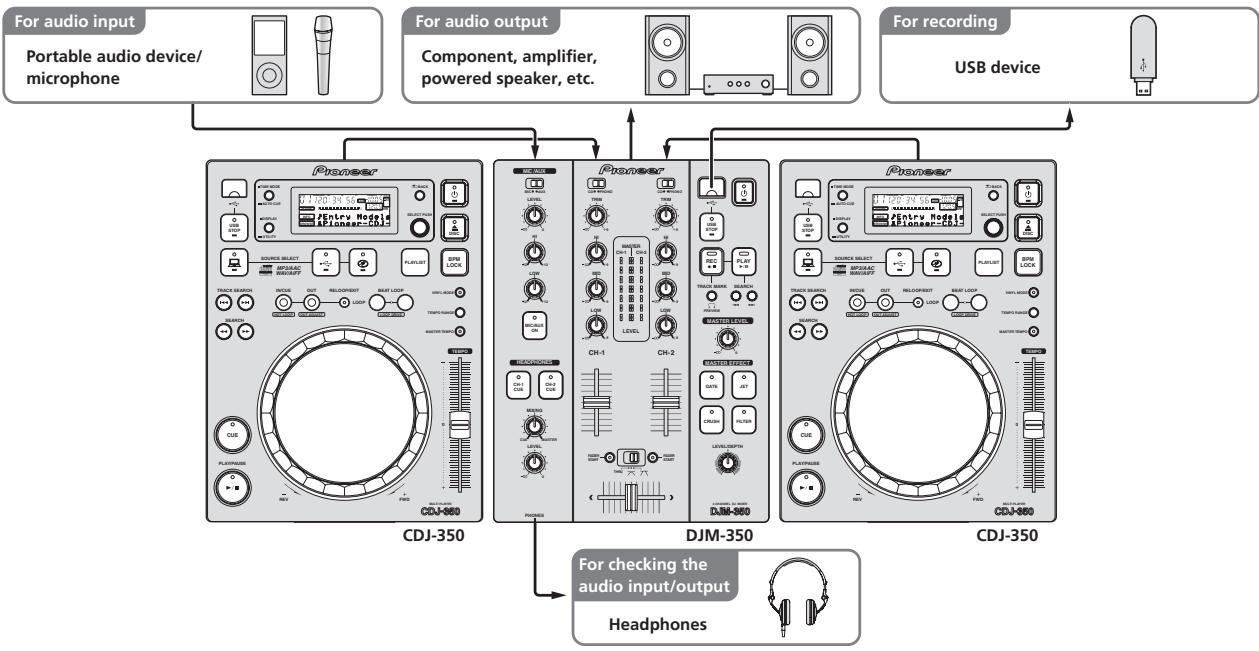
flowchart
graph TD
    A["For audio input\nPortable audio device/microphone"] --> B["Pioneer"]
    C["For audio output\nComponent, amplifier, powered speaker, etc."] --> B
    D["For recording\nUSB device"] --> E["Pioneer"]
    B --> F["CDJ-350"]
    E --> G["DJM-350"]
    F --> H["CP-1"]
    F --> I["CP-2"]
    G --> J["CP-3"]
    G --> K["CP-4"]
    H --> L["DAJ-350"]
    I --> M["DAJ-350"]
    J --> N["DAJ-350"]
    K --> O["DAJ-350"]
    L --> P["CP-1"]
    L --> Q["CP-2"]
    M --> R["CP-3"]
    N --> S["DAJ-350"]
    O --> T["DAJ-350"]
    P --> U["CP-1"]
    P --> V["CP-2"]
    Q --> W["CP-3"]
    R --> X["DAJ-350"]
    S --> Y["DAJ-350"]
    T --> Z["CP-1"]
    T --> AA["CP-2"]
    U --> AB["CP-3"]
    V --> AC["CP-4"]
    W --> AD["CP-1"]
    X --> AE["CP-2"]
    Y --> AF["CP-3"]
    Z --> AG["DAJ-350"]
    AA --> AH["DAJ-350"]
    AB --> AI["CP-1"]
    AB --> AJ["CP-2"]
    AC --> AK["CP-3"]
    AD --> AL["DAJ-350"]
    AE --> AM["DAJ-350"]
    AF --> AN["DAJ-350"]
    AG --> AO["CP-1"]
    AG --> AP["CP-2"]
    AH --> AQ["CP-3"]
    AI --> AR["DAJ-350"]
    AJ --> AS["DAJ-350"]
    AK --> AT["CP-1"]
    AK --> AU["CP-2"]
    AL --> AV["CP-3"]
    AM --> AW["DAJ-350"]
    AN --> AX["DAJ-350"]
    AO --> AY["CP-1"]
    AO --> AZ["CP-2"]
    AP --> BA["CP-3"]
    AQ --> BB["DAJ-350"]
    AR --> BC["DAJ-350"]
What's in the box
- Power cable
- Warranty card
- Operating instructions (this document)
Connections
Be sure to turn off the power and unplug the power cord from the power outlet whenever making or changing connections.
Refer to the operating instructions for the component to be connected.
Connect the power cord after all the connections between devices have been completed.
Be sure to use the included power cord.
Names of terminals
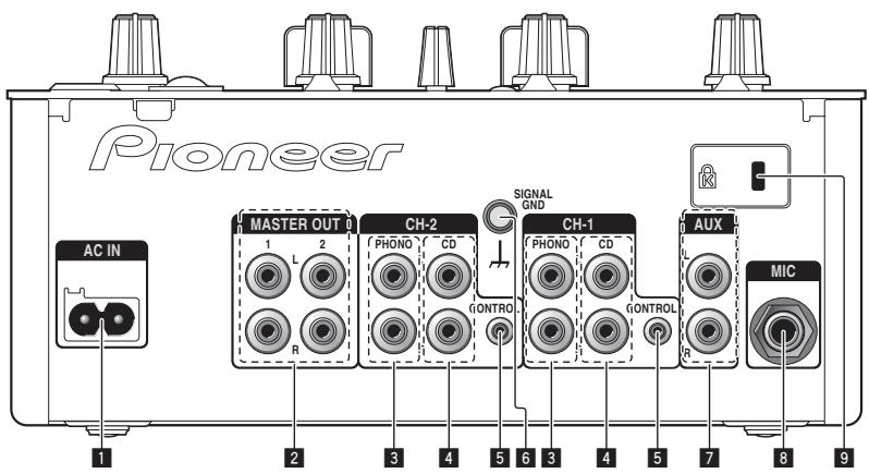
Rear panel
text_image
Pioneer AC IN MASTER OUT 1 1 L 2 CH-2 PHONO CD GONTROL SIGNAL GND CH-1 PHONO CD CONTROL AUX MIC 1 2 3 4 5 6 3 4 5 7 8 91 AC IN
Connect to an AC outlet. Plug in the power cord after all connections have been made.
Be sure to use the included power cord.
2 MASTER OUT 1, 2 (page 7)
Connect to a power amplifier, etc.
3 PHONO (page 7)
Connect to an analog player or other phono level (MM cartridge) output device. Do not connect to a DJ player or other line level device.
4 CD (page 7)
Connect to a DJ player or other line level device.
5 CONTROL (page 7)
Connect using a control cord (included with Pioneer DJ players).
6 SIGNAL GND (page 7)
Connect an analog player's ground wire here. This helps reduce noise when the analog player is connected.
7 AUX (page 7)
Connect to the output terminal of an external device (sampler, portable audio device, etc.)
8 MIC (page 7)
Connect to a microphone.
9 Kensington security slot
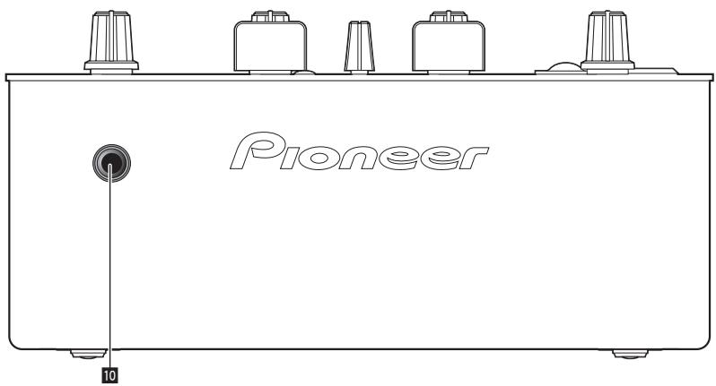
Front panel
text_image
Pioneer 1010 PHONES (page 7)
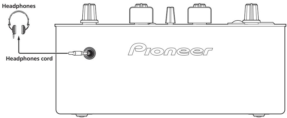
Connect headphones here.
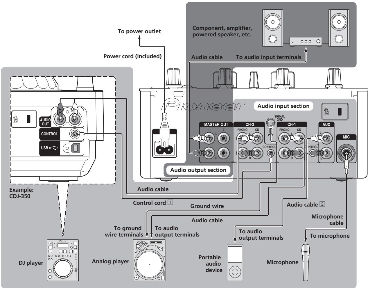
Connecting the input/output terminals
Rear panel
flowchart
graph TD
    A["Example: CDJ-350"] --> B["DJ player"]
    B --> C["Analog player"]
    C --> D["Portable audio device"]
    D --> E["Microphone"]
    E --> F["Microphone cable"]
    F --> G["To microphone"]
    G --> H["Ground wire"]
    H --> I["To ground wire terminals"]
    I --> J["Control cord 1"]
    J --> K["Audio cable"]
    K --> L["Audio output section"]
    L --> M["Audio cable"]
    M --> N["Ch-2"]
    N --> O["CH-1"]
    O --> P["AUX"]
    P --> Q["MIC"]
    Q --> R["Component, amplifier, powered speaker, etc."]
    R --> S["To audio input terminals"]
    S --> T["Audio cable"]
    T --> U["Power cord (included)"]
    U --> V["To power outlet"]
    V --> W["Audio output section"]
1 To use the fader start function, connect a control cord (page 10).
The fader start function can only be used when connected to a Pioneer DJ player.
2 A portable audio device can be connected using an RCA pin - mini-plug (∅ 3.5 mm) converter cable (page 11).
Front panel
text_image
Headphones Headphones cord PioneerOperations
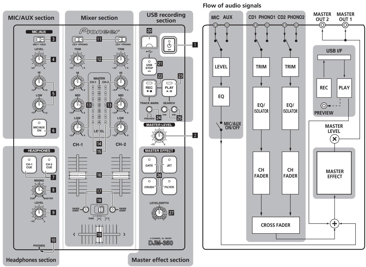
Control panel
flowchart
graph TD
    subgraph MIC/AUX Section
        A["MIC/AUX"] --> B["3"]
        B --> C["LEVEL"]
        C --> D["4"]
        D --> E["HI"]
        E --> F["LOW"]
        F --> G["6"]
        G --> H["Headphones section"]
    end

    subgraph Mixer Section
        I["Pioneer"] --> J["11"]
        J --> K["CD+@PHONO"]
        K --> L["TRIM"]
        L --> M["12"]
        M --> N["CH-1"]
        N --> O["HI"]
        O --> P["MID"]
        P --> Q["LOW"]
        Q --> R["9"]
        R --> S["CH-2"]
        S --> T["CH-2"]
        T --> U["CH-1"]
        U --> V["LE"]
        V --> W["THRU"]
        W --> X["13"]
        X --> Y["CH-2"]
        Y --> Z["CH-1"]
        Z --> AA["LE"]
        AA --> AB["THRU"]
        AB --> AC["15"]
        AC --> AD["Ch-1"]
        AD --> AE["14"]
        AE --> AF["CH-2"]
    end

    subgraph USB Recording Section
        AG["USB STOP"] --> AH["20"]
        AH --> AI["21"]
        AI --> AJ["22"]
        AJ --> AK["RECACT"]
        AK --> AL["TRACK MARK"]
        AL --> AM["PREVIEW"]
        AM --> AN["PLAY"]
        AN --> AO["SEARCH"]
        AO --> AP["23"]
        AP --> AQ["MASTER LEVEL"]
        AQ --> AR["24"]
        AR --> AS["25"]
    end

    subgraph Master Effect Section
        AT["MASTER EFFECT"] --> AU["2 CHANNEL DJ MIXER DJM-350"]
        AU --> AV["LEVEL/DEPTH"]
        AV --> AW["CRUSH"]
        AW --> AX["JET"]
        AX --> AY["GATE"]
        AY --> AZ["16"]
        AZ --> BA["MIXING"]
        BA --> BB["CUE"]
        BB --> BC["MASTER LEVEL"]
        BC --> BD["9"]
        BD --> BE["THRU"]
        BE --> BF["FADER START"]
        BF --> BG["17"]
        BG --> BH["FADER START"]
    end

    subgraph Flow of audio Signals
        BI["MIC AUX"] --> BJ["LEVEL"]
        BJ --> BK["EQ"]
        BK --> BL["MIC/AUX ON/OFF"]
        BL --> BM["Flow of audio signals"]

        BN["CD1 PHONO1 CD2 PHONO2"] --> BO["TRIM"]
        BO --> BP["EQ/ISOLATOR"]
        BP --> BQ["EQ/ISOLATOR"]
        BQ --> BR["CH FADER"]
        BR --> BS["CH FADER"]
        BS --> BT["CROSS FADER"]

        BU["USB I/F"] --> BV["REC"]
        BV --> BW["PLAY"]
        BW --> BX["PREVIEW"]

        BY["MASTER LEVEL"] --> CA["X"]
        CA --> CB["MASTER EFFECT"]

    end
1 ⏻ (Power switch) (page 9)
2 MASTER LEVEL (page 9)
MIC/AUX section
The sound of a microphone or external device (sampler, portable audio device, etc.) can be handled (page 11).
3 MIC, AUX
4 LEVEL
5 HI, LOW
6 MIC/AUX ON
Headphones section
The sound being input to this unit can be checked over headphones (page 11).
7 CH-1 CUE, CH-2 CUE
8 MIXING
9 LEVEL
10 PHONES
Mixer section
Two sets of audio signals can be adjusted separately for basic DJ mixing (page 9).
11 CD, PHONO (input selector switch)
12 TRIM
13 HI, MID, LOW
14 Master level indicator
15 Channel level indicator
16 Channel fader
17 FADER START
18 THRU, ✗, ✗ (crossfader curve selector switch)
19 Crossfader
USB recording section
DJ performances can be recorded onto and played from USB devices (page 12).
20 USB device insertion slot
21 USB STOP
22 REC ●/■
23 PLAY ▶/II
24 TRACK MARK (PREVIEW)
25 SEARCH ◀◀◀, ▶▶▶
Master effect section
Effects can be applied to the sound output from [MASTER OUT 1, 2] (page 11).
26 MASTER EFFECT (GATE, CRUSH, JET, FILTER)
27 LEVEL/DEPTH
About the power switch of this unit
To turn the power on
Press [⏻] 1.
Turn on the power of this unit.
The [◎] indicator lights green.
To set to the standby mode
When this unit's power is on, press [💡] 1 for at least 2 seconds.
This unit is set to the standby mode.
The [◎] indicator lights red.
- When [∅] is pressed again, the power turns on.
- This unit is equipped with an auto standby function. For details, see About the auto standby function on page 12.
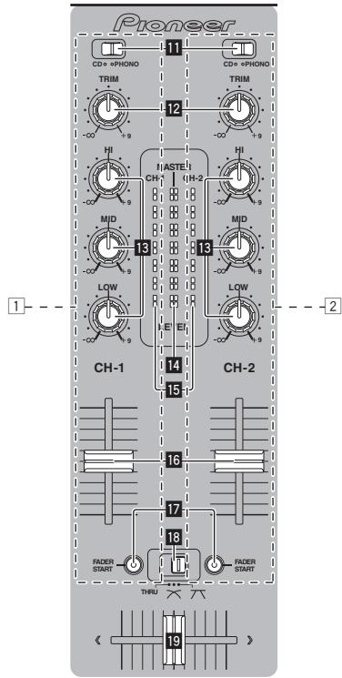
Basic operations (mixer section)
text_image
Pioneer 11 CD+ +PHONO TRIM 12 CD+ +PHONO 13 HI HI MID 14 CH-1 15 CH-2 16 17 FADER START THRU 18 FADER START 19Outputting sound
Check that this unit is properly connected to the DJ player, etc., before outputting sound. For instructions on connections, see Connecting the input/output terminals on page 7.
Set the volume of the power amplifiers connected to the [MASTER OUT 1, 2] terminals to an appropriate level. Note that very loud sounds will be output if the volume is set too high.
To output the sound of channel 1 [CH-1]
To output the sound of channel 2 ([CH-2]) 2 , perform the procedure below replacing [CH-1] with [CH-2].
1 Switch the [CD, PHONO] (input selector) switch 11 for the [CH-1] 1.
Select the input source for [CH-1] from among the devices connected to this unit.
— [CD]: Selects the DJ player connected to the [CD] terminals.
— [PHONO]: Selects the analog player connected to the [PHONO] terminals.
2 Turn the [TRIM] 12 control for the [CH-1] 1 clockwise.
Adjusts the audio level input to the [CH-1] terminal.
The [CH-1] channel level indicator 15 lights when audio signals are being properly input to [CH-1].
Adjust [TRIM] so that the orange indicator lights at the point in the track where the volume is loudest (the climax, etc.).
Be careful that the red indicator does not light, or the sound could be distorted.
3 Move the [CH-1] 1 channel fader 16 to the back side.
The level of the sound output from the [CH-1] terminals is adjusted.
4 Switch [THRU, X, X] (the crossfader curve selector switch) 18.
This switches the crossfader curve characteristics.
— [THRU]: Choose this when you do not want to use the crossfader.
— [✗]: Set here for a curve that rises gradually.
— [7]: Set here for a curve that rises steeply. (When the cross-fader moves away from either the left or right edge, the sound is immediately output from the opposite side.)
5 Move the crossfader 19.
Switch the channel whose sound is output from the speakers.
— Left edge: The [CH-1] sound is output.
— Center position: The sound of [CH-1] and [CH-2] is mixed and output.
— Right edge: The [CH-2] sound is output.
- This operation is not necessary when the [THRU, × , × ] (cross-fader curve selector) switch is set to [THRU].
6 Turn [MASTER LEVEL] 2 clockwise.
Sound is output from the speakers.
The master level indicator 14 on the control panel lights.
Adjust [MASTER LEVEL] so that the orange indicator lights at the point in the track where the volume is loudest (the climax, etc.).
Be careful that the red indicator does not light, or the sound could be distorted.
Adjusting the sound quality
Turn the [CH-1] 1 or [CH-2] 2 [HI], [MID] or [LOW] 13 control.
Refer to Specifications on page 16 for the range of sound that can be adjusted by each control.
- The sound for that range can be turned completely off by turning the control all the way counterclockwise (isolator function).
Mixing using the faders
Prepare the unit in advance so that the sound of [CH-1] is being output from the speakers. For instructions on preparation, see Outputting sound on page 9.
For instructions on monitoring the sound, see Monitoring the sound over headphones (headphones section) on page 11.
◆ Mixing using the channel faders
1 Set [THRU, X, X] (the crossfader curve selection switch) 18 to [THRU].
2 Switch the [CD, PHONO] (input selector) switch 11 for the [CH-2] 2.
3 Turn the [TRIM] 12 control for the [CH-2] 2 clockwise.
4 Press [CH-2 CUE] 7.
The sound of [CH-2] is monitored from the headphones.
5 Turn [MIXING] 8.
This adjusts the balance of the monitor volume between the sound output from the [MASTER OUT 1, 2] terminals (the sound of [CH-1]) and the sound of [CH-2].
6 Operate the DJ player connected to the [CH-2] terminals.
While checking the sound over the headphones, adjust the tempo of [CH-2] track to match the tempo of [CH-1] track.
7 While moving the [CH-2] 2 channel fader to the back, move the [CH-1] 1 channel fader to the front.
While checking the sound output from the speakers, operate the channel faders to substitute the sound of [CH-1] with the sound of [CH-2] . Mixing is completed once only the [CH-2] sound is being output from the speakers.
◆ Mixing using the crossfader
1 Set [THRU, X, X] (the crossfader curve selector switch) 18 to [X] or [X].
2 Operate [CH-2] 2.
Operate as described in steps 2 to 6 under Mixing using the channel faders on page 10.
3 Move the crossfader 19 gradually to the right.
While checking the sound output from the speakers, operate the crossfader to substitute the sound of [CH-1] with the sound of [CH-2] . Mixing is completed once only the [CH-2] sound is being output from the speakers.
Using the fader to play a Pioneer DJ player (fader start)
If you connect a Pioneer DJ player using a control cable (supplied with a DJ player), you can start playback of control other operations of the DJ player with the fader of this unit.
The fader start function can only be used when connected to a Pioneer DJ player.
Connect this unit and Pioneer DJ player beforehand. For instructions on connections, see Connecting the input/output terminals on page 7.
To start playback using the channel faders
1 Set [THRU, ✗, ✘] (the crossfader curve selection switch) 18 to [THRU].
2 Press [FADER START] 17.
Turn the fader start function on.
3 Move the channel fader 16 all the way to the front.
4 Set the cue on the DJ player.
The DJ player pauses playback at the cue point.
5 Move the channel fader 16 to the back.
Playback starts on the DJ player.
- If you set the channel fader back to the original position, the player instantaneously returns to the cue point already set and pauses playback (back cue).
To start playback using the crossfader
1 Set [THRU, X, X] (the crossfader curve selector switch) 18 to [X] or [X].
2 Press [FADER START] 17.
Turn the fader start function on.
3 Move the crossfader 19.
Move the crossfader to the opposite edge from the channel for which you want to use the fader start function.
4 Set the cue on the DJ player.
The DJ player pauses playback at the cue point.
5 Move the crossfader 19.
Playback starts on the DJ player.
- If you set the crossfader back to the original position, the player instantaneously returns to the cue point already set and pauses playback (back cue).
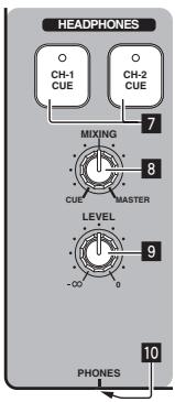
Monitoring the sound over headphones (headphones section)
text_image
HEADPHONES CH-1 CUE CH-2 CUE MIXING CUE MASTER LEVEL -∞ 0 7 8 9 10 PHONES1 Connect headphones to the [PHONES] jack.
For instructions on connections, see Connecting the input/output terminals on page 7.
2 Press [CH-1 CUE] or [CH-2 CUE] 7.
Select the channel you want to monitor.
— [CH-1 CUE]: The sound of [CH-1] is monitored.
— [CH-2 CUE]: The sound of [CH-2] is monitored.
- This operation is not necessary to monitor the master channel sound (the sound output from the [MASTER OUT 1, 2] terminals).
3 Turn [MIXING] 8.
— When turned counterclockwise: The volume of [CH-1] and [CH-2] becomes relatively louder.
— At the center position: The sound of [CH-1] and [CH-2] has the same volume as the sound from the [MASTER OUT 1, 2] terminals.
— When turned clockwise: The volume of the sound output from the [MASTER OUT 1, 2] terminals becomes relatively louder.
4 Turn [LEVEL] 9 in the headphones section clockwise.
Sound is output from the headphones.
- Monitoring is canceled when [CH-1 CUE] or [CH-2 CUE] is pressed again.
- Monitoring of the sound output from the [MASTER OUT 1, 2] terminals cannot be canceled.
Using the effect function (master effect section)
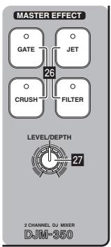
This unit is equipped with four effect buttons. When an effect button is pressed, the corresponding effect is applied to the audio signals output from the [MASTER OUT 1, 2] terminals.
text_image
MASTER EFFECT GATE JET 26 CRUSH FILTER LEVEL/DEPTH 27 2 CHANNEL DJ MIXER DJM-350Applying an effect
Press one of the [MASTER EFFECT (GATE, CRUSH, JET, FILTER)] 26 buttons.
The effect is applied to the sound.
The button that was pressed flashes.
The effect differs for the different buttons. For details on the different effects, see the table below.
- When a button that is flashing is pressed again, the effect is turned off.
| Effect Name | Descriptions | LEVEL/DEPTH |
| GATE | The distinctive range is cut from the sound of the track's rhythm section to give variation to the rhythm. | Left: The high range (high hat, etc.) is given variation.Right: The low range (bass drum, etc.) is given variation. |
| CRUSH | The sound is moderately crushed, adding accent. | Left: The sound is crushed and an effect as if the high range was gradually cut is achieved.Right: The sound is crushed and an effect as if the low range was gradually cut is achieved. |
| JET | An effect like a jet ascending and descending is achieved. | Left: An effect like a jet descending is achieved.Right: An effect like a jet ascending is achieved. |
| FILTER | The sound of the high or low range is filtered out, greatly changing the tone. | Left: An effect as if the high range was gradually cut is achieved.Right: An effect as if the low range was gradually cut is achieved. |
Varying the effect
Turn [LEVEL/DEPTH] 27.
The effect changes according to the direction in which the [LEVEL/DEPTH] is turned and its position.
- The original sound is output when [LEVEL/DEPTH] is set to the center position.
Using a microphone or external device (MIC/AUX section)
text_image
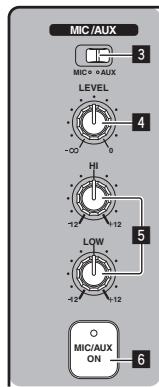
MIC /AUX MIC = AUX LEVEL HI LOW MIC/AUX ON1 Switch [MIC, AUX] 3.
— [MIC]: The microphone connected to the [MIC] terminal is selected.
— [AUX]: The external device connected to the [AUX] terminals is selected.
2 Press [MIC/AUX ON] 6.
3 Turn [LEVEL] 4 in the MIC/AUX section clockwise.
The sound of the microphone or external device is output from the speakers.
Adjusting the sound quality
Turn [HI] or [LOW] 5 in the MIC/AUX section.
Refer to Specifications on page 16 for the range of sound that can be adjusted by each control.
Recording the performance (USB recording section)
The same sound as the sound being output from the [MASTER OUT 1, 2] terminals can be recorded as a WAV file on a USB device.
- The name of the files created when the sound is recorded is in the format [REC***.WAV] (** is a 3-digit number).
flowchart
graph TD
    A["20"] --> B["USB STOP"]
    B --> C["21"]
    C --> D["22"]
    D --> E["23"]
    E --> F["24"]
    F --> G["25"]
    G --> H["24"]
    H --> I["TRACK MARK"]
    I --> J["24"]
    J --> K["SEARCH"]
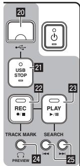
1 Insert the USB device into the USB device insertion slot 20.
The [USB STOP] indicator 21 flashes.
After a while, the [USB STOP] indicator stops flashing, remaining lit, and the recording standby mode is set.
2 Press [REC ●/■] 22.
Recording starts.
The [REC ●/■] indicator 22 flashes.
- When [REC ●/■] is pressed again, the [REC ●/■] indicator turns off and recording stops.
- Continuous recording is possible for 180 minutes. If recording continues for over 180 minutes, the recording data on the USB device is automatically split.
- Recording is possible for about 90 minutes on a 1 GB USB device.
Playing recorded tracks
Press [PLAY ▶/II] 23.
Playback starts.
The [PLAY ▶/II] indicator 23 lights.
- When [PLAY ▶/II] is pressed again, playback is paused.
- Only WAV files stored in the [PIONEER DJM / DJM350 REC] folder on the USB device can be played.
Previewing recorded tracks
1 Turn [MIXING] 8 counterclockwise from the center position.
2 Press and hold in [TRACK MARK (PREVIEW)] 24.
The sound of the recorded track can be heard over the headphones while the button is pressed.
- The sound being previewed is added to the sound of [CH-1] and [CH-2] and output from the headphones.
- The sound being previewed is not output from the speakers.
- Previewing is not possible while the track is being recorded or played.
Fast-forwarding/reversing recorded tracks
During playback, press and hold in [SEARCH ◀◀◀, ▶▶▶] 25.
The track is fast-forwarded when [▶▶] is pressed and held in.
The track is fast reversed when [I◀◀] is pressed and held in.
The [PLAY ▶/II] indicator flashes during fast-forwarding/reversing.
- Fast-forwarding/reversing is not possible when in the pause mode.
❖ Cuing to the beginning of recorded tracks
Press [SEARCH ◀◀◀, ▶▶▶] 25.
Press the [▶▶] to move to the beginning of the next track.
Press [I◄◄] once to move to the beginning of the currently playing track, twice to move to the beginning of the previous track.
Splitting tracks while recording
During recording, press [TRACK MARK (PREVIEW)] 24.
The currently recording track is split and stored on the USB device.
- When split tracks are played on this unit, the sound may be interrupted at the boundary between the two tracks.
Deleting recorded tracks
1 While playing the track, press [PLAY ▶/II] 23.
The track you want to delete is paused.
2 Press [PLAY ▶/II] 23 for at least 2 seconds.
The [REC ●/■] indicator flashes.
3 While pressing [PLAY ▶/■] 23, press [REC ●/■] 22.
The [REC ●/■] indicator lights and the track is deleted.
- Track deleting is canceled if [PLAY ▶/■] is released while the [REC ●/■] indicator is flashing.
Disconnecting USB devices
Always perform the following procedure to disconnect USB devices. Pulling the USB device out without performing this procedure could make the USB device unreadable.
When turning the set's power off, be sure to remove the USB device first.
1 Press [USB STOP] 21 for at least 1 second.
The [USB STOP] indicator flashes, then turns off.
2 Disconnect the USB device.
About the auto standby function
When the auto standby function is turned on, the power is automatically set to the standby mode after the set time has passed with all of the conditions below met.
— That none of this unit's buttons or controls are operated.
— That this unit's channel level indicator is not lit.
— That the USB device's recording and playback functions are not in use.
Setting the auto standby function
First set this unit to the standby mode.
1 Press [⏻] 1 while pressing [◀◀] and [▶▶] 25.
This unit switches to the mode for changing the auto standby function's setting.
The topmost point on the master level indicator flashes. The other points on the indicator light according to the currently set time.
2 Press [I◄◄] or [►►I] 25.
Set the time until the standby mode is set.
The set time switches each time the button is pressed.
The points on the master level indicator light according to the set time (not including the topmost point).
— Off — 20 minutes — 40 minutes — 60 minutes
— 20 minutes: The bottom two points light.
— 40 minutes: The bottom four points light.
— 60 minutes: The bottom six points light.
- The time is set to 20 minutes upon shipment from the factory.
3 Press [⏻] 1 for at least 2 seconds.
The new auto standby function setting is saved.
The [∅] indicator flashes green while the setting is being saved, then stops flashing, remaining lit, once the setting has been saved.
- Do not disconnect the power cord while the setting is being saved.
Additional information
Troubleshooting
- Incorrect operation is often mistaken for trouble or malfunction. If you think that there is something wrong with this component, check the points below. Sometimes the trouble may lie in another component. Inspect the other components and electrical appliances being used. If the trouble cannot be rectified after checking the items below, ask your nearest Pioneer authorized service center or your dealer to carry out repair work.
- This unit may not operate properly due to static electricity or other external factors. In this case, normal operation may be restored by unplugging the power cord, waiting about 5 seconds or more, then plugging the power cord back in.
| Problem | Check | Remedy |
| The power is not turned on. | Is the power cord properly connected? | Plug in the power cord to an AC outlet. (page 7) |
| No sound or small sound. | Is the [CD, PHONO] (input selector) switch set to the proper position? | Switch the [CD, PHONO] (input selector) switch to select the input source for that channel. (page 9) |
| Are the [TRIM], [channel fader], [crossfader] and [MASTER LEVEL] controls set to the proper positions? | Set the [TRIM], [channel fader], [crossfader] and [MASTER LEVEL] controls to the proper positions. (page 9) | |
| Are the connected components, amplifiers, etc., properly set? | Set the external input selection, volume, etc., on the components/amplifiers properly. | |
| Are the connection cables properly connected? | Connect the connection cables properly. (page 7) | |
| Are the terminals and plugs dirty? | Clean the terminals and plugs before making connections. | |
| Distorted sound. | Is [MASTER LEVEL] set at the proper position? | Adjust [MASTER LEVEL] so that the orange indicator on the master level indicator lights at the peak level. (page 9) |
| Is [TRIM] set at the proper position? | Adjust [TRIM] so that the orange indicator on the channel level indicator lights at the peak level. (page 9) | |
| Can't crossfade. | Is the [THRU, X, X] (crossfader curve selector) switch set to [THRU]? | Set the [THRU, X, X] (crossfader curve selector) switch to a position other than [THRU]. (page 9) |
| Can't fader start a DJ player. | Is [FADER START] set to off? | Set [FADER START] to on. (page 10) |
| Is the control cord properly connected? | Connect this unit and DJ player with a control cord. (page 7) | |
| Are the audio cables properly connected? | Connect this unit to the audio output terminal of a DJ player with an audio cable. (page 7) | |
| No effect. | Has one of the [MASTER EFFECT (GATE, CRUSH, JET, FILTER)] buttons been pressed? | Press one of the [MASTER EFFECT (GATE, CRUSH, JET, FILTER)] buttons. (page 11) |
| Is [LEVEL/DEPTH] set to the center position? | Turn [LEVEL/DEPTH] clockwise or counterclockwise. (page 11) | |
| No sound is produced or the sound is faint when playing a track recorded on a USB device. | Is [MASTER LEVEL] set at the proper position? | Before recording, adjust [MASTER LEVEL] so that the orange indicator on the master level indicator lights at the peak level. (page 9) |
| Sound is distorted when playing a track recorded on a USB device. | Is [TRIM] set at the proper position? | Before recording, adjust [TRIM] so that the orange indicator on the channel level indicator lights at the peak level. (page 9) |
| The sound of a recorded track cannot be previewed over the headphones even when [TRACK MARK (PREVIEW)] is pressed and held. | Is [MIXING] turned all the way clockwise? | Turn [MIXING] counterclockwise from the center position. (page 12) |
| USB device is not recognized. | Is the USB device properly connected? | Insert the USB device securely all the way in. (page 12) |
| Is the USB device one that can be used on this unit? | This unit supports such USB mass storage class USB devices as external hard disks and portable flash memory devices. |
About errors
If this unit cannot operate normally, the [☐] (the power switch), [USB STOP] and [PLAY ▶/II] indicators flash to indicate an error.
Check the table below and take the measures indicated.
If the same error is indicated after the measures have been taken, contact your store of purchase or nearby Pioneer service station.
About the [USB STOP] indicator's error indication
If the [USB STOP] indicator flashes repeatedly 2 to 5 times
1 Disconnect the USB device.
2 Press [USB STOP].
Check the table below and take the measures indicated.
| Indicator name | Number of times indicator flashes | Description of error | Cause | Measure |
| USB STOP | 2 times repeatedly | File format problem | USB device is not formatted. | Use a USB device formatted with a file system supported by this unit (FAT or HFS+). |
| You are using a USB device with a file system that is not supported by this unit. | ||||
| 3 times repeatedly | USB class problem | A device other than a USB mass storage class device is connected. | Connect a USB mass storage class USB device. | |
| A USB hub is connected. | Do not connect USB hubs. | |||
| 4 times repeatedly | Problem writing on the USB device | Not enough free space on the USB device. | Use a USB device with sufficient free space. | |
| There is a file name “REC999.WAV” in the recorded data storage folder (PIONEER DJM / DJM350 REC). | Files created through recording are given a 3-digit number. Once the number 999 is reached, no new files can be created in the folder. If this happens, move the files in the folder to a different folder. | |||
| USB device's write protect switch is set to the on position. | Set the USB device's write-protect switch to the off position. | |||
| You are using a USB device with a security function. | Use a USB device without a security function. | |||
| The recorded data storage folder (PIONEER DJM / DJM350 REC) is set to “Read Only”. | Change the setting so that the recorded data storage folder is writable. | |||
| 5 times repeatedly | USB device over-current detected | You are using a USB device (such as a bus power-driven hard disk) whose current is higher than this unit's rated current (500 mA). | Use a USB device within this unit's rated current (such as a hard disk driven by an AC adapter or other external power supply). | |
| PLAY ▶/II | 3 times | Playback error | There are no playable files in the recorded data storage folder (PIONEER DJM / DJM350 REC). | Perform the recording operation on this unit to create playable files before playing them. |
| ○(power switch) | Continuous | Circuit problem | There is a problem in the internal circuitry. | Unplug this unit's power cord from the power outlet. |
About USB devices/files usable on this unit
This unit supports external hard disks, portable flash memory devices and other USB mass storage class devices.
| Folder layers | Max. 2 layers (PIONEER DJM / DJM350 REC) |
| Max. number of files | Maximum 999 tracks |
| Supported file systems | FAT, FAT32 and HFS+ |
- Optical disk type devices such as external DVD/CD drives, etc., are not supported.
- When there are many folders or files, some time may be required for loading.
- If multiple partitions are set for the USB device, the device may not be recognized.
Cautions on using USB devices
- Some USB devices may not operate properly. Please note that Pioneer will accept no responsibility whatsoever for loss of data recorded on USB devices.
• USB hubs cannot be used.
• USB devices equipped with flash card readers may not operate.
- It may happen that, when a current stronger than the maximum allowable current is detected in this unit's USB port, the [USB STOP] indicator flashes 5 times, the power supply to the USB device is cut off, and communications with the USB device are interrupted. To restore normal operation, disconnect the USB device from this unit, then press [USB STOP]. Avoid reusing USB devices for which an excess current has been detected. If normal operation is not restored (if communications cannot be established) after the above procedure is performed, try turning off this unit's power then turning it back on.
- Depending on the USB device you are using, the desired performance may not be achieved.
About WAV files
The DJM-350 supports WAV files in the formats shown below.
| Compatible formats | Files in 16-bit non-compressed PCM format with a sampling frequency of 44.1 kHz are supported. |
| File extension | .WAV or .wav |
About the exemption clauses
• Pioneer is a registered trademark of Pioneer Corporation.
- The names of companies and products mentioned herein are the trademarks of their respective owners.
- When playing music files you have acquired on this unit, we kindly ask you to respect copyrights.
Specifications
General
Power requirements...... AC 220 V to 240 V, 50 Hz/60 Hz
Power consumption 17 W
Power consumption (standby)....0.4 W
Main unit weight 3.2 kg
Max. dimensions..... 218 mm (W) × 107 mm (H) × 301 mm (D)
Tolerable operating temperature....+5 °C to +35 °C
Tolerable operating humidity....5 % to 85 % (no condensation)
Audio Section
Sampling rate....48 kHz
A/D, D/A converter.... 24 bits
Frequency characteristic CD/AUX/MIC....20 Hz to 20 kHz
S/N ratio (rated output) CD....97 dB PHONO....86 dB MIC....80 dB
Total harmonic distortion (CD — MASTER1) 0.007 %
Standard input level / Input impedance CD....-12 dBu/36 kΩ PHONO....-52 dBu/47 kΩ MIC....-52 dBu/10 kΩ AUX....-12 dBu/27 kΩ
Standard output level / Load impedance / Output impedance MASTER OUT......+2 dBu/10 kΩ/2.5 Ω PHONES......+2 dBu/32 Ω/150 Ω
Rated output level / Load impedance MASTER OUT......+18 dBu/10 kΩ
Crosstalk (CD) 78 dB Channel equalizer characteristic
HI....- to + 9 dB (13 kHz) MID....- to + 9 dB (1 kHz) LOW....- to +9 dB (70 Hz)
MIC/AUX equalizer characteristics HI....-12 dB to +12 dB (10 kHz) LOW....-12 dB to +12 dB (100 Hz)
Input/output terminals
CD input terminal RCA pin jack....2 sets
PHONO input terminal RCA pin jack....2 sets
MIC input terminal Phone jack (∅ 6.3 mm) .... 1 set
AUX input terminal RCA pin jack....1 sets
MASTER output terminal RCA pin jack....2 sets
PHONES output terminal Stereo phone jack (∅ 6.3 mm) .... 1 set
USB terminal Type A.... 1 set
CONTROL terminal Mini phone jack (∅ 3.5 mm)....2 sets
- The specifications and design of this product are subject to change without notice.
• Published by Pioneer Corporation. Copyright © 2010 Pioneer Corporation. All rights reserved.
text_image
Pioneer 1010 PHONES (la page 7)
3 MIC, AUX
4 LEVEL
5 HI, LOW
6 MIC/AUX ON
La lecture commence.
text_image
Pioneer 1010 PHONES (Seite 7)
3 MIC, AUX
4 LEVEL
5 HI, LOW
6 MIC/AUX ON
Kopfhörer-Sektion
text_image
MIC /AUX MIC = AUX LEVEL -00 0 HI -12 112 LOW -12 112 O MIC/AUX ON 61 Schalter [MIC, AUX] 3.
text_image
Pioneer 103 MIC, AUX
4 LEVEL
5 HI, LOW
6 MIC/AUX ON
Sezione cuffia
text_image
MIC /AUX MIC = AUX LEVEL HI LOW MIC/AUX ONWAARSCHUWING NETSNOER
text_image
Pioneer 103 MIC, AUX
4 LEVEL
5 HI, LOW
6 MIC/AUX ON
natural_image
Line drawing of a Pioneer electric vehicle battery casing with mounting ports and a circular vent (no text or symbols on the diagram itself)3 MIC, AUX
4 LEVEL
5 HI, LOW
6 MIC/AUX ON
PHONO....86 dB MIC....80 dB
text_image
Pioneer 1010 PHONES (стр. 7)
3 MIC, AUX
4 LEVEL
5 HI, LOW
6 MIC/AUX ON
Раздел наушников
Published by Pioneer Corporation.
Copyright © 2010 Pioneer Corporation.
All rights reserved.
Publication de Pioneer Corporation.
© 2010 Pioneer Corporation.