
DJM-900NXS - DJ mixer PIONEER - Free user manual and instructions
Find the device manual for free DJM-900NXS PIONEER in PDF.
User questions about DJM-900NXS PIONEER
0 question about this device. Answer the ones you know or ask your own.
Ask a new question about this device
Download the instructions for your DJ mixer in PDF format for free! Find your manual DJM-900NXS - PIONEER and take your electronic device back in hand. On this page are published all the documents necessary for the use of your device. DJM-900NXS by PIONEER.
USER MANUAL DJM-900NXS PIONEER
The Pioneer website shown above offers FAQs, information on software and various other types of information and services to allow you to use your product in greater comfort.
Operating Instructions
Mode d'emploi
Bedienungsanleitung
IHCTpyKcnnn no 3Kcnpnyataaun
Thank you for buying this Pioneer product. Please read through these operating instructions so you will know how to operate your model properly. After you have finished reading the instructions, put them away in a safe place for future reference. In some countries or regions, the shape of the power plug and power outlet may sometimes differ from that shown in the explanatory drawings. However the method of connecting and operating the unit is the same.
IMPORTANT

The lightning flash with arrowhead symbol, within an equilateral triangle, is intended to alert the user to the presence of uninsulated "dangerous voltage" within the product's enclosure that may be of sufficient magnitude to constitute a risk of electric shock to persons.
CAUTION
RISK OF ELECTRIC SHOCK DO NOT OPEN
CAUTION:
TO PREVENT THE RISK OF ELECTRIC SHOCK,DO NOT REMOVE COVER (OR BACK).NO USER-SERVICEABLE PARTS INSIDE.REFER SERVICING TO QUALIFIED SERVICE PERSONNEL.

The exclamation point within an equilateral triangle is intended to alert the user to the presence of important operating and maintenance (servicing) instructions in the literature accompanying the appliance.
D3-4-2-1-1_A1_En
Replacement and mounting of an AC plug on the power supply cord of this unit should be performed only by qualified service personnel.
IMPORTANT: THE MOULDED PLUG
This appliance is supplied with a moulded three pin mains plug for your safety and convenience. A 10 amp fuse is fitted in this plug. Should the fuse need to be replaced, please ensure that the replacement fuse has a rating of 10 amps and that it is approved by ASTA or BSI to BS1362.
Check for the ASTA mark or the BSI mark on the body of the fuse.
If the plug contains a removable fuse cover, you must ensure that it is refitted when the fuse is replaced. If you lose the fuse cover the plug must not be used until a replacement cover is obtained. A replacement fuse cover can be obtained from your local dealer.
If the fitted moulded plug is unsuitable for your socket outlet, then the fuse shall be removed and the plug cut off and disposed of safely. There is a danger of severe electrical shock if the cut off plug is inserted into any 13 amp socket.
If a new plug is to be fitted, please observe the wiring code as shown below. If in any doubt, please consult a qualified electrician.
IMPORTANT: The wires in this mains lead are coloured in accordance with the following code: Blue : Neutral Brown : Live
As the colours of the wires in the mains lead of this appliance may not correspond with the coloured markings identifying the terminals in your plug, proceed as follows;
The wire which is coloured BLUE must be connected to the terminal which is marked with the letter N or coloured BLACK.
The wire which is coloured BROWN must be connected to the terminal which is marked with the letter L or coloured RED.
How to replace the fuse: Open the fuse compartment with a screwdriver and replace the fuse.
D3-4-2-1-2-2*A2_EN

If you want to dispose this product, do not mix it with general household waste. There is a separate collection system for used electronic products in accordance with legislation that requires proper treatment, recovery and recycling.
Private households in the member states of the EU, in Switzerland and Norway may return their used electronic products free of charge to designated collection facilities or to a retailer (if you purchase a similar new one).
For countries not mentioned above, please contact your local authorities for the correct method of disposal.
By doing so you will ensure that your disposed product undergoes the necessary treatment, recovery and recycling and thus prevent potential negative effects on the environment and human health.
K058b_A1_En
WARNING
This equipment is not waterproof. To prevent a fire or shock hazard, do not place any container filled with liquid near this equipment (such as a vase or flower pot) or expose it to dripping, splashing, rain or moisture.
D3-4-2-1-3_A1_En
WARNING
Before plugging in for the first time, read the following section carefully.
The voltage of the available power supply differs according to country or region. Be sure that the power supply voltage of the area where this unit will be used meets the required voltage (e.g., 230 V or 120 V) written on the side panel.
D3-4-2-1-4*A1En
WARNING
To prevent a fire hazard, do not place any naked flame sources (such as a lighted candle) on the equipment.
D3-4-2-1-7a_A1_En
VENTILATION CAUTION
When installing this unit, make sure to leave space around the unit for ventilation to improve heat radiation (at least 5 cm at rear, and 3 cm at each side).
WARNING
Slots and openings in the cabinet are provided for ventilation to ensure reliable operation of the product, and to protect it from overheating. To prevent fire hazard, the openings should never be blocked or covered with items (such as newspapers, table-cloths, curtains) or by operating the equipment on thick carpet or a bed.
D3-4-2-1-7b*A1En
Operating Environment
Operating environment temperature and humidity: +5^ to +35^ (+41^ to +95^) ; less than 85% RH (cooling vents not blocked)
Do not install this unit in a poorly ventilated area, or in locations exposed to high humidity or direct sunlight (or strong artificial light)
D3-4-2-1-7c*A1En
If the AC plug of this unit does not match the AC outlet you want to use, the plug must be removed and appropriate one fitted. Replacement and mounting of an AC plug on the power supply cord of this unit should be performed only by qualified service personnel. If connected to an AC outlet, the cut-off plug can cause severe electrical shock. Make sure it is properly disposed of after removal. The equipment should be disconnected by removing the mains plug from the wall socket when left unused for a long period of time (for example, when on vacation).
D3-4-2-2-1a_A1_En
CAUTION
The POWER switch on this unit will not completely shut off all power from the AC outlet. Since the power cord serves as the main disconnect device for the unit, you will need to unplug it from the AC outlet to shut down all power. Therefore, make sure the unit has been installed so that the power cord can be easily unplugged from the AC outlet in case of an accident. To avoid fire hazard, the power cord should also be unplugged from the AC outlet when left unused for a long period of time (for example, when on vacation).
D3-4-2-2-2a*A1_EN
POWER-CORD CAUTION
Handle the power cord by the plug. Do not pull out the plug by tugging the cord and never touch the power cord when your hands are wet as this could cause a short circuit or electric shock. Do not place the unit, a piece of furniture, etc., on the power cord, or pinch the cord. Never make a knot in the cord or tie it with other cords. The power cords should be routed such that they are not likely to be stepped on. A damaged power cord can cause a fire or give you an electrical shock. Check the power cord once in a while. When you find it damaged, ask your nearest PIONEER authorized service center or your dealer for a replacement.
S002*A1En
Contents
How to read this manual
The names of displays, menus, and buttons in this manual are enclosed in brackets. (e.g. [MASTER] channel, [ON/OFF], [File] menu)
01 Before start
Features 5
What's in the box. 5
12 Connections
Rear panel.. 6
Connecting input terminals. 7
Connecting output terminals.. 7
Connecting to the control panel.. 8
About the driver software and setting utility software.. 8
Operations
Control Panel. 11
Basic Operation. 13
Advanced Operations. 14
Types of effects
Types of SOUND COLOR FX effects. 17
Types of BEAT EFFECT. 17
05 List of MIDI Messages
06 Changing the settings
About the auto standby function. 22
About the talk over function.. 22
Setting preferences.. 22
07 Additional information
Troubleshooting 23
Block Diagram 24
Disclaimer 25
Specifications 25
Before start
Features
This unit is a standard type DJ mixer for professional DJs that carries over the technology of the Pioneer DJM series, the world standard in club sound. Not only is it equipped with a wide variety of functions for DJ performances, including PRO DJ LINK, SOUND COLOR FX and BEAT EFFECT, it also uses a high sound quality design and a panel layout with high operability to provide strong support for performances to all professional DJs active in the club scene.
SOUND CARD
This unit is equipped with "sound card/USB audio interface".
- Up to 4 sets of audio signals from a single computer can be assigned to the different channels and mixed.
- DVS (Digital Vinyl System) software time code signals played from a DJ player or analog player can be output to the user's DVS software. This enables DJ play using DVS software without all the complicated connections.
- Up to 4 sets of audio signals from the different channels (channels 1 to 4, REC OUT, crossfader sides A and B and microphone) can be output to the computer. This is very convenient for recording the mixed sound.
HIGH SOUND QUALITY
Efforts have been made for improved sound quality in the digital/analog inputs/outputs. Sound processing with 96 kHz sampling, a 24-bit high sound quality A/D converter and a 32-bit high sound quality D/A converter result in more powerful, high grade sound.
96 kHz 24-bit USB audio is supported.
SOUND COLOR FX
This unit is equipped with 6 types of effects. Effects can be obtained simply by turning the [COLOR] controls provided for each of the channels, letting DJs adjust the sound quality of the tracks input to the different channels and make improvisational performances.
BEAT EFFECT
The BEAT EFFECT function well-received on the DJM series is carried over and further evolved.
This unit has been newly equipped with an [X-PAD] for achieving various effects by touch operation, allowing you to achieve intuitive live performances with great freedom.
CHANNEL FADER
A newly developed high reliability fader is used for the channel fader.
Compared to channel faders on previous models in the DJM series, this new fader offers improved endurance with respect to deterioration due to dust, liquids, etc., getting on the fader. Smooth operation is maintained even under tough usage conditions.
PRO DJ LINK
The PRO DJ LINK functions can be used when a Pioneer DJ player supporting PRO DJ LINK (CDJ-2000, CDJ-900 etc.), a computer on which rekordbox is installed and this unit are connected by LAN cable.
For details on PRO DJ LINK, see About PRO DJ LINK on page 14.
STANDARD LAYOUT
This unit carries over the control panel layout of the Pioneer DJM series, the world standard in DJ mixers.
The simple, straightforward control panel layout not only facilitates DJ performances but lets even DJs using this unit for the first time to operate it without hesitation, so it can be used without worry as a mixer that is permanently installed in the club.
What's in the box
- CD-ROM
USB cable
Power cord
Warranty card - Operating instructions (this document)
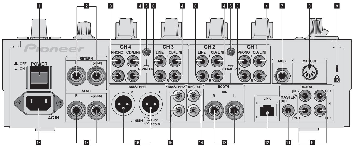
Connections
Be sure to turn off the power and unplug the power cord from the power outlet whenever making or changing connections.
Refer to the operating instructions for the component to be connected.
Connect the power cord after all the connections between devices have been completed.
Be sure to use the included power cord.
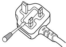
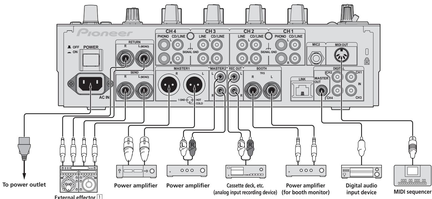
Rear panel
1 POWER button (page 13)
Turns this unit's power on and off.
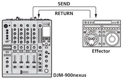
2 RETURN terminals (page 7)
Connect to the output terminal of an external effector. When the [L (MONO)]
channel only is connected, the [L (MONO)] channel input is simultaneously input to the [R] channel.
3 PHONO terminals (page 7)
Connect to a phono level (MM cartridge) output device. Do not input line level signals.
To connect a device to the [PHONO] terminals, remove the short-circuit pin plug inserted in the terminals.
Insert this short-circuit pin plug into the [PHONO] terminals when nothing is connected to them to cut external noise.
4 CD/LINE terminals (page 7)
Connect to a DJ player or a line level output component.
5 SIGNAL GND terminal (page 7)
Connect an analog player's ground wire here. This helps reduce noise when the analog player is connected.
6 LINE terminals (page 7)
Connect to a cassette deck or a line level output component.
MIC2 terminal (page 7)
Connect a microphone here.
8 MIDI OUT terminal (page 7)
Connect this to the MIDI IN terminal on an external MIDI sequencer.
9 Kensington security slot
10 DIGITAL IN terminal (page 7)
Connect these to the digital coaxial output terminals on DJ players, etc. The sound may be momentarily interrupted when the output signal sampling frequency is switched.
DIGITAL MASTER OUT terminals (page 7)
Outputs the master channel audio signals.
LINK terminal (page 7)
Connect these to the LINK terminals on Pioneer DJ players or the LAN ports of computers on which rekordbox is installed (PRO DJ LINK).
To connect multiple devices, use a switching hub (commercially available).
Use a 100Base-TX-compatible switching hub. Some switching hubs may not operate properly.
13 BOOTH terminals (page 7)
Output terminals for a booth monitor, compatible with balanced or unbalanced output for a TRS connector.
14 REC OUT terminals (page 7)
This is an output terminal for recording.
15 MASTER2 terminals (page 7)
Connect to a power amplifier, etc.
16 MASTER1 terminals (page 7)
Connect to a power amplifier, etc.
17 SEND terminals (page 7)
Connect to the input terminal of an external effector. When the [L (MONO)] channel only is connected, a monaural audio signal is output.
18 AC IN
Connect to a power outlet using the included power cord. Wait until all connections between the equipment are completed before connecting the power cord. Be sure to use the included power cord.
WARNING
The short-circuit pin plugs out of the reach of children and infants. If accidentally swallowed, contact a doctor immediately.
Connecting input terminals
- When creating a DVS (Digital Vinyl System) combining a computer, audio interface, etc., be careful in connecting the audio interface to this unit's input terminals and in the settings of the input selector switches.
Also refer to the operating instructions of the DJ software and audio interface.
For details on PRO DJ LINK, see About PRO DJ LINK on page 14.
2 To use the fader start function, connect a LAN cable (page 13).
Connecting output terminals
1 Also connect the external effector to the [RETURN] terminal (input terminal).
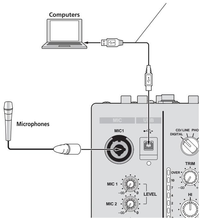
Connecting to the control panel
Be sure to connect using the included USB cable.
About the driver software and setting utility software
This driver software is a proprietary program for inputting and outputting audio signals from the computer. To use this unit connected to a computer on which a Windows or Mac OS is installed, install the driver software on the computer beforehand.
Software end user license agreement
This Software End User License Agreement ("Agreement") is between you (both the individual installing the Program and any single legal entity for which the individual is acting) ("You" or "Your") and PIONEER CORPORATION ("Pioneer"). TAKING ANY STEP TO SET UP OR INSTALL THE PROGRAM MEANS THAT YOU ACCEPT ALL OF THE TERMS OF THIS LICENSE AGREEMENT. PERMISSION TO DOWNLOAD AND/OR USE THE PROGRAM IS EXPRESSLY CONDITIONED ON YOUR FOLLOWING THESE TERMS. WRITTEN OR ELECTRONIC APPROVAL IS NOT REQUIRED TO MAKE THIS AGREEMENT VALID AND ENFORCEABLE. IF YOU DO NOT AGREE TO ALL OF THE TERMS OF THIS AGREEMENT, YOU ARE NOT AUTHORIZED TO USE THE PROGRAM AND MUST STOP INSTALLING IT OR UNINSTALL IT, AS APPLICABLE.
1 Definitions
1 "Documentation" means written documentation, specifications and help content made generally available by Pioneer to aid in installing and using the Program.
"Program" means all or any part of Pioneer's software licensed to You by Pioneer under this Agreement.
2 Program license
1 Limited License. Subject to this Agreement's restrictions, Pioneer grants to You a limited, non-exclusive, nontransferable, license (without the right to sublicense):
a To install a single copy of the Program on the hard disk drive of Your computer, to use the Program only for Your personal purpose complying with this Agreement and the Documentation ("Authorized Use");
b To use the Documentation in support of Your Authorized Use; and
c To make one copy of the Program solely for backup purposes, provided that all titles and trademark, copyright and restricted rights notices are reproduced on the copy.
2 Restrictions. You will not copy or use the Program or Documentation except as expressly permitted by this Agreement. You will not transfer, sublicense, rent, lease or lend the Program, or use it for third-party training, commercial time-sharing or service bureau use. You will not Yourself or through any third party modify, reverse engineer, disassemble or decompile the Program, except to the extent expressly permitted by applicable law, and then only after You have notified Pioneer in writing of Your intended activities. You will not use the Program on multiple processors without Pioneer's prior written consent.
Ownership. Pioneer or its licensor retains all right, title and interest in and to all patent, copyright, trademark, trade secret and other intellectual property rights in the Program and Documentation, and any derivative works thereof. You do not acquire any other rights, express or implied, beyond the limited license set forth in this Agreement.
No Support. Pioneer has no obligation to provide support, maintenance, upgrades, modifications or new releases for the Program or Documentation under this Agreement.
3 Warranty disclaimer
THE PROGRAM AND DOCUMENTATION ARE PROVIDED "AS IS" WITHOUT ANY REPRESENTATIONS OR WARRANTYES, AND YOU AGREE TO USE THEM AT YOUR SOLE RISK. TO THE FULlest EXTENT PERMISSIBLE BY LAW, PIONEER EXPRESSLY DISCLAIMS ALL WARRANTYES OF ANY KIND WITH RESPECT TO THE PROGRAM AND DOCUMENTATION, WHETHER EXPRESS, IMPLIED, STATUTORY OR ARISING OUT OF COURSE OF PERFORMANCE, COURSE OF DEALING OR USAGE OF TRADE, INCLUDING ANY WARRANTYES OF MERCHANTABILITY, FITNESS FOR A PARTICULAR PURPOSE, SATISFACTORY QUALITY, ACCURACY, TITLE OR NON-INFRINGEMENT.
4 Damages and remedies for breach
You agree that any breach of this Agreement's restrictions would cause Pioneer irreparable harm for which money damages alone would be inadequate. In addition to damages and any other remedies to which Pioneer may be entitled, You agree that Pioneer may seek injunctive relief to prevent the actual, threatened or continued breach of this Agreement.
5 Termination
Pioneer may terminate this Agreement at any time upon Your breach of any provision. If this Agreement is terminated, You will stop using the Program, permanently delete it from the computer where it resides, and destroy all copies of the Program and Documentation in Your possession, confirming to Pioneer in writing that You have done so. Sections 2.2, 2.3, 2.4, 3, 4, 5 and 6 will continue in effect after this Agreement's termination.
6 General terms
1 Limitation of Liability. In no event will Pioneer or its subsidiaries be liable in connection with this Agreement or its subject matter, under any theory of liability, for any indirect, incidental, special, consequential or punitive damages, or damages for lost profits, revenue, business, savings, data, use, or cost of substitute procurement, even if advised of the possibility of such damages or if such damages are foreseeable. In no event will Pioneer's liability for all damages exceed the amounts actually paid by You to Pioneer or its subsidiaries for the Program. The parties acknowledge that the liability limits and risk allocation in this Agreement are reflected in the Program price and are essential elements of the bargain between the parties, without which Pioneer would not have provided the Program or entered into this Agreement.
The limitations or exclusions of warranties and liability contained in this Agreement do not affect or prejudice Your statutory rights as consumer and shall apply to You only to the extent such limitations or exclusions are permitted under the laws of the jurisdiction where You are located.
3 Severability and Waiver. If any provision of this Agreement is held to be illegal, invalid or otherwise unenforceable, that provision will be enforced to the extent possible or, if incapable of enforcement, deemed to be severed and deleted from this Agreement, and the remainder will continue in full force and effect. The waiver by either party of any default or breach of this Agreement will not waive any other or subsequent default or breach.
No Assignment. You may not assign, sell, transfer, delegate or otherwise dispose of this Agreement or any rights or obligations under it, whether voluntarily or involuntarily, by operation of law or otherwise, without Pioneer's prior written consent. Any purported assignment, transfer or delegation by You will be null and void. Subject to the foregoing, this Agreement will be binding upon and will inure to the benefit of the parties and their respective successors and assigns.
5 Entire Agreement. This Agreement constitutes the entire agreement between the parties and supersedes all prior or contemporaneous agreements or representations, whether written or oral, concerning its subject matter. This Agreement may not be modified or amended without Pioneer's prior and express written consent, and no other act, document, usage or custom will be deemed to amend or modify this Agreement.
6 You agree that this Agreement shall be governed and construed by and under the laws of Japan.
Cautions on Installation
- Before installing the driver software, be sure to turn off the power of this unit and disconnect the USB cable from both this unit and your computer.
- If you connect this unit to your computer without installing the driver software first, an error may occur on your computer depending on the system environment.
- If you have discontinued the installation process in progress, step through the installation process again from the beginning according to the following procedure.
- Read Software end user license agreement carefully before installing this unit's proprietary driver software.
- Before installing the driver software, terminate all other programs running on your computer.
- The driver software is compatible with the following OSs.
Supported operating systems
| Mac OS X (10.3.9 and later) | ✓ | |
| Windows® 7 Home Premium/Professional/Ultimate | 32-bit version | ✓ |
| 64-bit version | ✓ | |
| Windows Vista® Home Basic/Home Premium/Business/Ultimate | 32-bit version | ✓ |
| 64-bit version | ✓ | |
| Windows® XP Home Edition/Professional (SP2 or later) | 32-bit version | ✓ |
Windows® XP Professional x64 Edition is not supported.
- The included CD-ROM includes installation programs in the following 12 languages.
English, French, German, Italian, Dutch, Spanish, Portuguese, Russian, Simplified Chinese, Traditional Chinese, Korean, and Japanese When using operating systems in other languages, follow the instructions on the screen to select [English (English)].
Installing the driver software
Installation Procedure (Windows)
Read Cautions on Installation carefully before installing the driver software.
- To install or uninstall the driver software, you need to be authorized by the administrator of your computer. Log on as the administrator of your computer before proceeding with the installation.
1 Insert the included CD-ROM into the computer's CD drive.
The CD-ROM folder appears.
- If the CD-ROM folder is not displayed after a CD-ROM is loaded, open the CD drive from [Computer (or My Computer)] in the [Start] menu.
2 Double-click [DJM-900 nexus_X.XXX.exe].
The driver installation screen appears.
3 When the language selection screen appears, select [English] and click [OK].
You can select one from multiple languages depending on the system environment of your computer.
4 Carefully read the Software end user license agreement and if you consent to the provisions, put a check mark in [I agree.] and click [OK].
If you do not consent to the provisions of the Software end user license agreement, click [Cancel] and stop installation.
5 Proceed with installation according to the instructions on the screen.
If [Windows Security] appears on the screen while the installation is in progress, click [Install this driver software anyway] and continue with the installation.
- When installing on Windows XP
If [Hardware Installation] appears on the screen while the installation is in progress, click [Continue Anyway] and continue with the installation. - When the installation program is completed, a completion message appears.
- When the installation of the driver software is completed, you need to reboot your computer.
Installation Procedure (Macintosh)
Read Cautions on Installation carefully before installing the driver software.
- To install or uninstall the driver software, you need to be authorized by the administrator of your computer. Have the name and password of the administrator of your computer ready in advance.
1 Insert the included CD-ROM into the computer's CD drive.
The CD-ROM folder appears.
- Double-click the CD icon on the desktop when folders are not displayed after a CD-ROM has been loaded.
2 Double-click [DJM-900 nexus_M_X.X.X.dmg].
The [DJM-900nexusAudioDriver] menu screen appears.
3 Double-click [DJM-900nexusAudioDriver pkg].
The driver installation screen appears.
4 Check the details on the screen and click [Continue Anyway].
5 When the Software Use Agreement screen appears, select [English], carefully read the Software end user license agreement and click [Continue Anyway].
You can select one from multiple languages depending on the system environment of your computer.
6 If you consent to the provisions of the Software end user license agreement, click [Agree].
If you do not consent to the provisions of the Software end user license agreement, click [I disagree] and stop installation.
7 Proceed with installation according to the instructions on the screen.
- Click [Cancel] to cancel installation after it has started.
- When the installation of the driver software is completed, you need to reboot your computer.
Connecting this unit and computer
1 Connect this unit to your computer via a USB cable.
This unit functions as an audio device conforming to the ASIO standards.
This operation does not work with computers that do not support USB 2.0.
- When using ASIO-compatible applications, [USB 1/2], [USB 3/4], [USB 5/6] and [USB 7/8] can be used as inputs.
- When using DirectX-compatible applications, only [USB 1/2] can be used as the input.
- The computer's recommended operating environment depends on the DJ application. Be sure to check the recommended operating environment for the DJ application you are using.
- When another USB audio device is connected to the computer at the same time, it may not operate or be recognized normally.
We recommend only connecting the computer and this unit.
- When connecting the computer and this unit, we recommend connecting directly to this unit's USB port.
2 Press [POWER] button.
Turn on the power of this unit.
- The message [Installing device driver software] may appear when this unit is first connected to the computer or when it is connected to a different USB port on the computer. Wait awhile until the message [Your devices are ready for use] appears.
-
When installing on Windows XP
-
[Can Windows connect to Windows Update to search for software?] may appear while the installation is in progress. Select [No, not this time], then click [Next] to continue installation.
- [What do you want the wizard to do?] may appear while the installation is in progress. Select [Install the software automatically (Recommended)], then click [Next] to continue installation.
- If [Windows Security] appears on the screen while the installation is in progress, click [Install this driver software anyway] and continue with the installation.
About the setting utility software
The setting utility can be used to make the checks and settings described below.
- Checking the status of this unit's [DIGITAL, CD/LINE, PHONO, LINE, USB */] selector switch
Setting the audio data output from this unit to the computer
Adjusting the buffer size (when using Windows ASIO) - Checking the version of the driver software
Displaying the setting utility
For Windows
Click [Start] menu > [All Programs] > [Pioneer] > [DJM-900nexus] > [DJM-900nexus Settings Utility].
For Mac OS X
Click [Macintosh HD] icon > [Application] > [Pioneer] > [DJM-900nexus] > [DJM-900nexus Settings Utility].
Checking the status of this unit's [DIGITAL, CD/LINE, PHONO, LINE, USB \*/\*] selector switch
Display the setting utility before starting.
Click the [MIXER INPUT] tab.
![PIONEER DJM-900NXS - Click the [MIXER INPUT] tab. - 1](/content/2019/11/118942/images/d9ac3a693a4548a016efca8254a5d8c23b73f827a7eecb798f208c5f66721446.jpg)
Setting the audio data output from this unit to the computer
Display the setting utility before starting.
1 Click the [MIXER OUTPUT] tab.
![PIONEER DJM-900NXS - Click the [MIXER OUTPUT] tab. - 1](/content/2019/11/118942/images/fe1ab1c2c953aed44fd4869b5540d4b132b5a646ae76134fc34cc0d791e47496.jpg)
2 Click the [Mixer Audio Output] pull-down menu.
Select and set the audio data to be output to the computer from the flow of audio signals inside this unit.
| CH1 | CH2 | CH3 | CH4 |
| CH1 Timecode PHONO1 | CH2 Timecode CD/ LINE1 | CH3 Timecode CD/ LINE1 | CH4 Timecode PHONO1 |
| CH1 Timecode CD/ LINE1 | CH2 Timecode LINE1 | CH3 Timecode LINE1 | CH4 Timecode CD/ LINE1 |
| CH1 Timecode DIGITAL1 | CH2 Timecode DIGITAL1 | CH3 Timecode DIGITAL1 | CH4 Timecode DIGITAL1 |
| POST CH1 Fader2 | POST CH2 Fader2 | POST CH3 Fader2 | POST CH4 Fader2 |
| Cross Fader A2 | Cross Fader A2 | Cross Fader A2 | Cross Fader A2 |
| Cross Fader B2 | Cross Fader B2 | Cross Fader B2 | Cross Fader B2 |
| MIC | MIC | MIC | MIC |
| REC OUT2 | REC OUT2 | REC OUT2 | REC OUT2 |
1: The audio data is output with the same volume at which it is input to this unit, regardless of the [USB Output Level] setting.
2): When using for applications other than recording, pay attention to the DJ application's settings so that no audio loops are generated. If audio loops are generated, sound may be input or output at unintended volumes.
3 Click the [USB Output Level] pull-down menu.
Adjust the volume of the audio data output from this unit.
- The [USB Output Level] setting is applied equally to all audio data. However, when 1 on the table at step 2 is selected, the audio data is output with the same volume at which it is input to this unit.
- If not enough volume can be achieved with the DJ software's volume adjustment alone, change the [USB Output Level] setting to adjust the volume of the audio data output from this unit. Note that the sound will be distorted if the volume is raised too high.
Adjusting the buffer size (when using Windows ASIO)
If an application using this unit as the default audio device (DJ software, etc.) is running, quit that application before adjusting the buffer size.
Display the setting utility before starting.
Click the [ASIO] tab.
![PIONEER DJM-900NXS - Click the [ASIO] tab. - 1](/content/2019/11/118942/images/63a8af93516a05de776d17d4833538bd840a43ea8c6f2d34390478d2718aca13.jpg)
- If the buffer size is made large, drops in audio data (breaks in the sound) occur less easily, but the time lag due to the delay in the transfer of the audio data (latency) increases.
Checking the version of the driver software
Display the setting utility before starting.
Click the [About] tab.
![PIONEER DJM-900NXS - Click the [About] tab. - 1](/content/2019/11/118942/images/497f8751083b5efabe4794c4477837416f524abad117d2265166d680068bc8b3.jpg)
Checking the latest information on the driver software
For the latest information on the driver software for exclusive use with this unit, visit our website shown below.
http://www.prodjnet.com/support/
- Operation cannot be guaranteed when multiple units of this mixer are connected to a single computer.
Control Panel
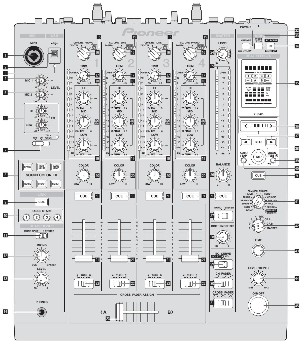
MIC1 terminal (page 14)
Connect a microphone here.
2 USB terminal (page 8)
Connect the computer.
3 USB connection indicator
Lights when signals are being exchanged with the computer.
4 MIC1 LEVEL control (page 14)
Adjusts the sound level output from the [MIC1] channel.
MIC2 LEVEL control (page 14)
Adjusts the sound level output from the [MIC2] channel.
6 EQ (HI, LOW) controls (page 14)
These adjust the tone quality of the [MIC1] and [MIC2] channels.
OFF, ON, TALK OVER selector switch (page 14)
Turns the microphone on/off.
8 SOUND COLOR FX buttons (page 14)
These turn the SOUND COLOR FX effects on/off.
9 CUE buttons (page 13)
Press the [CUE] button(s) for the channel(s) you want to monitor.
10 FADER START (1, 2, 3, 4) buttons (page 13)
These turn the fader start function on/off.
11 MONO SPLIT, STEREO selector switch (page 13)
Switches how the monitor sound output from the headphones is distributed.
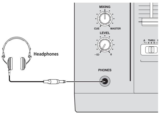
12 MIXING controls (page 13)
These adjust the monitor volume balance of the sound of channels for which the [CUE] button is pressed and the sound of the [MASTER] channel.
LEVEL control (page 13)
Adjusts the sound level output from the headphones.
14 PHONES terminal (page 13)
Connect headphones here.
15 USB audio input indicator
Lights when sound is being input from the computer to the various channels.
16 DIGITAL, CD/LINE, PHONO, LINE, USB */* selector switch (page 13)
Select the input source of each channel from the components connected to this unit.
17 TRIM control (page 13)
Adjusts the level of audio signals input in each channel.
18 EQ/ISO (HI, MID, LOW) controls (page 13)
These adjust the sound quality of the different channels.
19 Channel Level Indicator (page 13)
Displays the sound level of the different channels before passing through the channel faders.
20 COLOR controls (page 14)
These change the parameters of the SOUND COLOR FX of the different channels.
21 Channel Fader (page 13)
Adjusts the level of audio signals output in each channel.
22 CROSS FADER ASSIGN (A, THRU, B) selector switch (page 13)
Set the output destination of each channel to [A] or [B].
23 Crossfader (page 13)
Outputs audio signals assigned by the crossfader assign switch corresponding to the curve characteristics selected by [CROSS FADER] (Crossfader Curve Selector Switch).
24 MASTER LEVEL controls (page 13)
Adjusts the sound level output from the [MASTER] channel.
25 Master Level Indicator (page 13)
Displays the sound level output from the [MASTER] channel.
26 BALANCE controls (page 14)
Adjusts the left/right balance of the sound output from the [MASTER1] terminals, etc.
27 MONO, STEREO selector switch (page 14)
Switches the sound output from the [MASTER1] terminals, etc., between mon-aural and stereo.
28 BOOTH MONITOR controls (page 14)
Adjusts the level of audio signals output at the [BOOTH] terminal.
29 EQ CURVE (ISOLATOR, EQ) selector switch (page 13)
Switches the function of the [EQ/ISO (HI, MID, LOW)] controls.
30 CH FADER ( , ,) selector switch (page 13)
Switches the channel fader's curve characteristics.
31 CROSS FADER (一,一,一) selector switch (page 13)
This switches the crossfader curve characteristics.
32 ON/OFF (UTILITY) button
ON/OFF:Turns the MIDI function on/off (page 16).
- UTILITY: Displays the [USER SETUP] or [CLUB SETUP] screen (page 22).
38 START/STOP button (page 16)
Sends the MIDI start/MIDI stop signals.
34 LFO FORM (WAKE UP) button
LFO FORM: When [MIDI LFO] is selected at BEAT EFFECT, the MIDI signal's waveform switches each time the button is pressed (page 19).
- WAKE UP: Cancels the auto standby mode (page 22).
Main unit display
36 X-PAD (page 15)
Adjusts the quantitative parameter of the BEAT EFFECT function.
57 BEAT , buttons (page 15)
Sets the beat fraction for synchronizing the effect sound.
58 TAP (ENTER) button
TAP: When the BPM measurement mode is set to [TAP], the BPM is input manually by tapping the button with a finger (page 15).
- ENTER: Used to change this unit's settings (page 22).
39 QUANTIZE button
Used to change this unit's settings (page 22).
- When the QUANTIZE function is turned on for BEAT EFFECT, the effect is applied to the sound without going off tempo when the currently playing track. (page 15).
40 AUTO/TAP button (page 15)
Switches the BPM measurement mode.
41 DELAY, ECHO, SPIRAL, REVERB, TRANS, FILTER, FLANGER, PHASER, ROBOT, MELODIC, SLIP ROLL, ROLL, REV ROLL, SND/RTN (MIDI LFO) selector switch (page 15)
Switches the BEAT EFFECT effect type.
42 1, 2, 3, 4, MIC, CF.A, CF.B, MASTER selector switch (page 15) Switches the channel to which the BEAT EFFECT is to be applied.
TIME control (page 15)
Adjust the BEAT EFFECT's time parameter.
44 LEVEL/DEPTH control (page 15)
Adjusts the BEAT EFFECT's quantitative parameter.
45 ON/OFF button (page 15)
Turns the BEAT EFFECT function on/off.
Do not pull on the channel fader and crossfader knobs with excessive force. The knobs are not designed to be removed. Pulling the knobs strongly may result in damaging the unit.
Basic Operation
Outputting sound
1 Press [POWER] button.
Turn on the power of this unit.
2 Turn the [DIGITAL, CD/LINE, PHONO, LINE, USB /] selector switch.
Select the input sources for the different channels from among the devices connected to this unit.
- [DIGITAL]: Selects the DJ player connected to the [DIGITAL] terminals.
- [PHONO]: Selects the analog player connected to the [PHONO] terminals.
- [CD/LINE], [LINE]: Selects the cassette deck or CD player connected to the [LINE] terminals.
- [USB / ]: Selects the sound of the computer connected to the [USB] port.
3 Turn the [TRIM] control.
Adjusts the level of audio signals input in each channel.
The corresponding channel level indicator lights when audio signals are being properly input to that channel.
4 Set the channel fader to the inner position.
Adjusts the level of audio signals output in each channel.
5 Switch the [CROSS FADER ASSIGN (A, THRU, B)] selector switch.
Switches the output destination of each channel.
[A]: Assigns to [A] (left) of the crossfader.
[B]: Assigns to [B] (right) of the crossfader.
- [THRU]: Select this when you do not want to use the crossfader. (The signals do not pass through the crossfader.)
6 Set the crossfader.
This operation is not necessary when the [CROSS FADER ASSIGN (A, THRU, B)] selector switch is set to [THRU].
7 Turn the [MASTER LEVEL] control.
Audio signals are output from the [MASTER1] and [MASTER2] terminals.
The master level indicator lights.
Adjusting the sound quality
Turn the [EQ/ISO (HI, MID, LOW)] controls for the different channels.
Refer to Specifications on page 25 for the range of sound that can be adjusted by each control.
Switching the function of the [EQ/ISO (HI, MID, LOW)] controls
Switch the [EQ CURVE (ISOLATOR, EQ)] selector switch.
[ISOLATOR]: Functions as an isolator.
- [EQ]: The equalizer function is set.
Monitoring sound with headphones
1 Connect headphones to the [PHONES] jack.
2 Press the [CUE] button(s) for the channel(s) you want to monitor.
3 Switch the [MONO SPLIT, STEREO] selector switch.
- [MONO SPLIT]: The sound of the channels for which the [CUE] button is pressed is output from the headphones output's left channel, the [MASTER] channel sound is output from the right channel.
- [STEREO]: The sound of the channels for which the [CUE] button is pressed is output from the headphones in stereo.
4 Turn the [MIXING] control.
These adjust the monitor volume balance of the sound of channels for which the [CUE] button is pressed and the sound of the [MASTER] channel.
5 Turn the [LEVEL] control for [HEADPHONES].
The sound of the channels for which the [CUE] button is pressed is output from the headphones.
- When the [CUE] button is pressed again, monitoring is canceled.
Monitoring the sound of the computer
- Check [Use "LINK MONITOR" of Pioneer DJ Mixers.] at [File] > [Preferences] > [Audio] inrekordbox beforehand. Also refer to therekordbox operating instructions.
1 Connect headphones to the [PHONES] jack.
2 Connect a computer on which rekordbox is installed.
For instructions on connections, see Connecting input terminals on page 7.
3 Selecting the track to be monitored withrekordbox
4 Press the [CUE] button for [LINK].
The track selected withrekordbox is output from the headphones.
- When the [CUE] button is pressed again, monitoring is canceled.
- The same operation as at Monitoring sound with headphones (steps 3 to 5) can be performed.
Switching the fader curve
Select the channel fader curve characteristics.
Switch the [CH FADER ( , ,) ] selector switch.
- [J]: The curve rises suddenly at the back side.
- []: A curve between the ones above and below is set.
- []: The curve rises gradually (the sound gradually increases as the channel fader is moved away from the front side).
Select the crossfader curve characteristics.
Switch the [CROSS FADER (六, 六, 六)] selector switch.
- [N]: Makes a sharply increasing curve (if the crossfader is moved away from the [A] side, audio signals are immediately output from the [B] side).
- [N]: Makes a curve shaped between the two curves above and below.
- [X] : Makes a gradually increasing curve (if the crossfader is moved away from the [A] side, the sound on the [B] side gradually increases, while the sound on the [A] gradually decreases).
Starting playback on a DJ player using the fader (fader start)
When connected to a Pioneer DJ player by LAN cable, such operations as starting playback on the DJ player can be controlled using this unit's fader.
Connect this unit and Pioneer DJ player beforehand. For instructions on connections, see Connecting input terminals on page 7.
For instructions on setting the player numbers of Pioneer DJ players, see About PRO DJ LINK on page 14.
The fader start function can be switched on and off for all DJ players all at once. For the switching procedure, see Changing the settings on page 22.
Start playback using the channel fader
1 Set the [CROSS FADER ASSIGN (A, THRU, B)] selector switch to [THRU].
2 Press one of the [FADER START (1, 2, 3, 4)] buttons.
Select the channel to be started with the fader start function.
3 Set the channel fader to the outermost position.
4 Set the cue on the DJ player.
The DJ player pauses playback at the cue point.
5 Set the channel fader to the inner position.
Playback starts on the DJ player.
- If you set the channel fader back to the original position, the player instantaneously returns to the cue point already set and pauses playback (back cue).
Start playback using the crossfader
1 Set the [CROSS FADER ASSIGN (A, THRU, B)] selector switch to [A] or [B].
2 Press one of the [FADER START (1, 2, 3, 4)] buttons.
Select the channel to be started with the fader start function.
3 Set the crossfader.
Set to the edge opposite the side on which the channel you want to use with the fader start function is set.
4 Set the cue on the DJ player.
The DJ player pauses playback at the cue point.
5 Set the crossfader.
Playback starts on the DJ player.
- If you set the crossfader back to the original position, the player instantaneously returns to the cue point already set and pauses playback (back cue).
Using a microphone
1 Connect a microphone to the [MIC1] or [MIC2] terminal.
2 Set the [OFF, ON, TALK OVER] selector switch to [ON] or [TALK OVER].
- ON: The indicator lights.
— [TALK OVER]: The indicator flashes.
- When set to [TALK OVER], the sound of channels other than the [MIC] channel is attenuated by 18 dB (default) when a sound of -10 dB or greater is input to the microphone.
- The [TALK OVER] sound attenuation level can be changed at [USER SETUP]. For instructions on changing this, see Changing the settings on page 22.
3 Turn the [MIC1 LEVEL] or [MIC2 LEVEL] control.
Adjust the level of the sound output from the [MIC] channel.
- Pay attention that rotating to the extreme right position outputs a very loud sound.
4 Input audio signals to the microphone.
Adjusting the sound quality
Turn the [MIC] channels' [EQ (HI, LOW)] controls.
Refer to Specifications on page 25 for the range of sound that can be adjusted by each control.
Switching between monaural and stereo audio
This switches the sound output from the [MASTER1], [MASTER2], [BOOTH], [REC OUT], [PHONES], [DIGITAL MASTER OUT] and [USB] terminals between monaural and stereo.
- To adjust the sound output from the [USB] terminals, select [REC OUT] at [Mixer Audio Output] in the setting utility.
Switch the [MONO, STEREO] selector switch.
- [MONO]: Outputs monaural audio.
- [STEREO]: Outputs stereo audio.
Adjusting the L/R balance of audio
The left/right balance of the sound output from the [MASTER1], [MASTER2], [BOOTH], [REC OUT], [PHONES], [DIGITAL MASTER OUT] and [USB] terminals can be adjusted.
- To adjust the sound output from the [USB] terminals, select [REC OUT] at [Mixer Audio Output] in the setting utility.
1 Set the [MONO, STEREO] selector switch to [STEREO].
2 Turn the [BALANCE] control.
The sound's left/right balance changes according to the direction in which the [BALANCE] control is turned and its position.
- Rotating to the rightmost position outputs only the right sound of stereo audio. Rotating to the leftmost position outputs only the left sound of stereo audio.
Audio is output from the [BOOTH] terminal
Turn the [BOOTH MONITOR] control.
Adjusts the level of audio signals output at the [BOOTH] terminal.
Advanced Operations
About PRO DJ LINK
When a PRO DJ LINK-compatible Pioneer DJ player (CDJ-2000, CDJ-900 etc.), a computer on which rekordbox is installed and this unit are connected by LAN cable, the PRO DJ LINK functions below can be used.
For more details on the PRO DJ LINK function, also refer to the DJ player's handling instructions and rekordbox's operating instructions.
For instructions on connections, see Connecting input terminals on page 7.
- When connected using a switching hub, up to 4 DJ players and 2 computers can be connected.
- Use a 100Base-TX-compatible switching hub. Some switching hubs may not operate properly.
- Set the DJ player's player number to the same number as the channel to which the audio cable is connected.
LINK MONITOR
With this function,rekordbox music files stored on the computer can be quickly monitored over the headphones.
STATUS INFORMATION
This function informs the DJ players of the connected channel status (on-air status, channel number, etc.).
QUANTIZE
When tracks analyzed withrekordbox are used, the track is put on beat even when the [ON/OFF] button of [BEAT EFFECTS] is pressed or the [X-PAD] is touched roughly.
FADER START
Playback on the DJ player can be started by operating this unit's fader (Fader Start Play).
SOUND COLOR FX
These effects change in association with the [COLOR] controls for the different channels.
1 Press one of the [SOUND COLOR FX] buttons.
This selects the type of effect.
The button that was pressed flashes.
- For the types of effects, see Types of SOUND COLOR FX effects on page 17.
The same effect is set for [CH1] to [CH4].
2 Turn the [COLOR] control.
The effect is applied to the channel(s) for which the control(s) was (were) pressed.
BEAT EFFECT
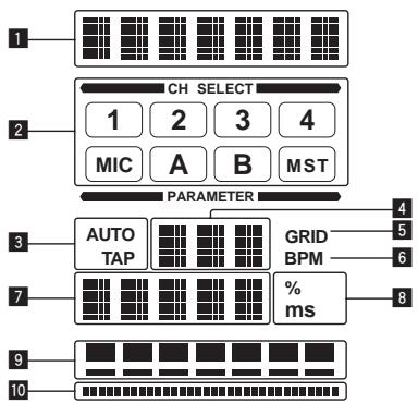
This function lets you instantaneously set various effects according to the tempo (BPM = Beats Per Minute) of the currently playing track.
| 1 | Effect display section | The name of the selected effect is displayed. |
| 2 | Channel select display section | The name of the channel to which the effect is applied is displayed. |
| 3 | AUTO (TAP) | [AUTO] lights when the BPM measurement mode is set to the auto mode. [TAP] lights when in the manual input mode. |
| 4 | BPM value display (3 digits) | When in the auto mode, this displays the automatically detected BPM value. When the BPM cannot be detected, the previously detected BPM value is displayed and flashes. When in the manual input mode, this displays the BPM value that was input manually. |
| 5 | GRID | When playing tracks that have been analyzed with rekord-box, this lights when the QUANTIZE function can be used in combination with the DJ player. This flashes or remains off if the QUANTIZE function cannot be used. |
| 6 | BPM | This is always lit. |
| 7 | Parameter display section | This displays the parameters specified for the individual effects. When the [BEAT←] button is pressed, the corresponding beat fraction is displayed for 1 second. When a value outside the parameter range is specified with the [BEAT←] button, the value does not change and the display flashes. |
| 8 | % (ms) | These light according to the units for the different effects. |
| 9 | Beat display section | This lights according to the selected beat number position. |
| 10 | Touch display section | This lights when the [X-PAD] is touched. |
1 Press [AUTO/TAP] button.
Select the BPM measurement mode.
-
[AUTO]: The BPM is measured automatically from the audio signal that is being input. The [AUTO] mode is set when this unit's power is turned on.
-
[TAP]: The BPM is input manually by tapping the [TAP] button with a finger.
-
The [AUTO] BPM measurement range is BPM = 70 to 180. With some tracks it may not be possible to measure the BPM correctly. If the BPM cannot be measured, the BPM value on the display flashes. In such cases, use the [TAP] button to input the BPM manually.
2 Turn the [DELAY, ECHO, SPIRAL, REVERB, TRANS, FILTER, FLANGER, PHASER, ROBOT, MELODIC, SLIP ROLL, ROLL, REV ROLL, SND/RTN (MIDI LFO)] selector switch.
This selects the type of effect.
For the types of effects, see Types of BEAT EFFECT on page 17.
To use [SND/RTN], see Using the external effector below.
To use [MIDI LFO], see Using the MIDl LFO on page 16.
3 Turn the [1, 2, 3, 4, MIC, CF.A, CF.B, MASTER] selector switch.
This selects the channel to which the effect is applied.
- [1] - [4]: The effect is applied to the sound of the respective channel.
- [MIC]: The effect is applied to the sound of [MIC] channel.
- [CF.A], [CF.B]: The effect is applied to the sound of the crossfader's [A] (left)
or [B] (right) side.
-
[MASTER]: The effect is applied to the sound of the [MASTER] channel.
-
This operation is not necessary when [MIDI LFO] is selected.
4 Press the [BEAT ] button.
Sets the beat fraction for synchronizing the effect sound.
The effect time corresponding to the beat fraction is set automatically.
5 Press the [ON/OFF] button for [BEAT EFFECTS].
The effect is applied to the sound.
The effect's time parameter can be adjusted by turning the [TIME] control.
The effect's quantitative parameter can be adjusted by turning the [LEVEL/DEPTH] control.
The [ON/OFF] button flashes when the effect is on.
- When the [ON/OFF] button is pressed again, the effect turns off.
Inputting the BPM manually
Tap the [TAP] button at least 2 times in rhythm with the beat (in quarter notes) of the sound being played.
The average value of the interval at which the [TAP] button was tapped by finger is set as the BPM.
- When the BPM is set using the [TAP] button, the beat fraction is set to [1/1] and the time of one beat (quarter note) is set as the effect time.
- The BPM can be set manually by turning the [TIME] control while pressing the [TAP] button.
- The BPM can be set in units of 0.1 by pressing the [AUTO/TAP] button while pressing the [TAP] button and turning the [TIME] control while pressing the two buttons.
Using the external effector
1 Connect this unit and external effector.
For instructions on connections, see Connecting output terminals on page 7.
2 Turn the [DELAY, ECHO, SPIRAL, REVERB, TRANS, FILTER, FLANGER, PHASER, ROBOT, MELODIC, SLIP ROLL, ROLL, REV ROLL, SND/RTN (MIDI LFO)] selector switch.
Select [SND/RTN (MIDI LFO)].
3 Turn the [1, 2, 3, 4, MIC, CF.A, CF.B, MASTER] selector switch.
This selects the channel to which the effect is applied.
4 Press the [ON/OFF] button for [BEAT EFFECTS].
The sound that has passed through the external effector is output from the [MASTER] channel.
- When the [ON/OFF] button is pressed again, the effect turns off.
Using the QUANTIZE function
Based on the GRID information of tracks that have been analyzed withrekordbox, effects can be added to the sound without getting out of tempo with the currently playing track.
Connect this unit and PRO DJ LINK-compatible Pioneer DJ player in advance. For instructions on connections, see Connecting input terminals on page 7.
Music files must be analyzed with rekordbox in advance in order to use the QUANTIZE function. For instructions on analyzing music files with rekordbox, also refer to the rekordbox operating instructions.
- The QUANTIZE function cannot be used when [REVERB], [ROBOT], [MELODIC] or [SND/RTN(MIDI LFO)] is selected.
- To use in combination with the CDJ-2000 or CDJ-900, first update the firmware to version 4.0 or later. (As of February 2011)
1 Press the [QUANTIZE] button.
The QUANTIZE function turns on.
[GRID] lights on this unit's main unit display when the GRID information has been properly received from the DJ player and the QUANTIZE function can be used.
[GRID] flashes if the GRID information could not be properly received.
- Depending on the status of the DJ player (off air, scratching, reverse playing, etc.), it may not be possible to receive the GRID information.
2 Press the [ON/OFF] button of [BEAT EFFECTS] or touch the [X-PAD].
The effect is added to the sound in tempo with the track being played.
- When the [QUANTIZE] button is pressed again, the QUANTIZE function turns off.
Operating the [X-PAD]
| Operating procedure | [ON/OFF] button status of [BEAT EFFECTS] | X-PAD | Effect |
| ① | Off (lit) | Release ⇌ Touch | On ⇌ Off |
| ② | On (flashing) | Release ⇌ Touch | On ⇌ On |
Operating procedure ①
1 Perform steps 1 to 4 of the BEAT EFFECT procedure.
2 Touch the [X-PAD].
The [X-PAD] turns the effect on and off and changes the quantitative parameter.
- When you release your finger from the [X-PAD], the effect turns off.
- To keep the effect on when you release your finger from the [X-PAD], while touching the [X-PAD] press the [ON/OFF] button of [BEAT EFFECTS], then release your finger from the [X-PAD].
1 Perform steps 1 to 5 of the BEAT EFFECT procedure.
2 Touch the [X-PAD].
The [X-PAD] changes the effect's quantitative parameter.
Operating DJ software using the MIDI function
This unit outputs the operation information of buttons and controls in universal MIDI format.
When connected by USB cable to a computer on which a MIDI-compatible DJ software program is installed, the DJ software can be operated from this unit. Install the DJ software on your computer in advance. Also, adjust audio and MIDI settings for the DJ software.
- For MIDI channel setting instructions, see Changing the settings on page 22.
- For the messages output by this unit, see List of MIDI Messages on page 20.
1 Connect this unit's [USB] terminal to the computer.
For details about connections, see Connecting to the control panel on page 8.
2 Start the DJ software.
3 Press the [ON/OFF (UTILITY)] button.
Turn the MIDI function on.
Transmission of the MIDI messages begin.
- When a fader or control is moved, a message corresponding to the position is sent.
- When the [START/STOP] button is pressed and held in for more than 2 seconds, a set of MIDI messages corresponding to the button, fader or control positions is sent (Snapshot).
- When the [ON/OFF (UTILITY)] button is pressed again, sending of the MIDI messages is stopped.
- The MIDI timing clock (BPM information) is sent regardless of the status of the [ON/OFF (UTILITY)] button.
Making the preparations to use the MIDI LFO function
The MIDI-compatible software, devices, etc. (referred to as the "MIDI signal reception side" below) must be prepared ("learned") before using the MIDI LFO function. Perform the learning operations on the MIDI signal reception side.
- For the messages output by this unit, see List of MIDI Messages on page 20.
1 Press the [ON/OFF (UTILITY)] button.
Turn the MIDI function on.
2 Turn the [DELAY, ECHO, SPIRAL, REVERB, TRANS, FILTER, FLANGER, PHASER, ROBOT, MELODIC, SLIP ROLL, ROLL, REV ROLL, SND/RTN (MIDI LFO)] selector switch.
Select [SND/RTN (MIDI LFO)].
[S/R←LFO] flashes on the effect display section, then [SND/RTN] is displayed.
3 Press the [ON/OFF] button for [BEAT EFFECTS].
Learn the [ON/OFF] button's MIDI message of the [BEAT EFFECTS] in the MIDI signal reception side.
- The MIDI message sent from the [ON/OFF] button of the [BEAT EFFECTS] differs when [SND/RTN (MIDI LFO)] is selected and when anything other than [SND/RTN (MIDI LFO)] is selected.
The [ON/OFF] button's MIDI message of [BEAT EFFECTS] when [SND/RTN (MIDI LFO)] is selected is only sent when the operation is performed following this procedure.
4 Press the [LFO FORM (WAKE UP)] button.
Learn the [LFO FORM (WAKE UP)] button's MIDI message in the MIDI signal reception side.
[1/7] and [1/7 LFO] are displayed alternately on the effect display section.
- If necessary, set the MIDI mapping for other buttons and controls. Because the [LFO FORM (WAKE UP)] button's MIDI message is sent sequentially, depending on the MIDI signal reception side's settings, it may not be possible to learn the MIDI message. To set the MIDI mapping for other buttons and controls, press the [LFO FORM(WAKE UP)] button to switch to [SND/RTN].
Using the MIDI LFO
Make the preparations following the procedure at Making the preparations to use the MIDI LFO function beforehand.
1 Turn the [DELAY, ECHO, SPIRAL, REVERB, TRANS, FILTER, FLANGER, PHASER, ROBOT, MELODIC, SLIP ROLL, ROLL, REV ROLL, SND/RTN (MIDI LFO)] selector switch.
Select [SND/RTN (MIDI LFO)].
[S / R LFO] flashes on the effect display section, then [SND/RTN] is displayed.
2 Press the [LFO FORM (WAKE UP)] button.
Transmission of the MIDI signals begins.
The MIDI signal waveform pattern switches each time the [LFO FORM (WAKE UP)] button is pressed.
$$ \left[\begin{array}{l}\rightarrow [ \text {S N D / R T N} ] \rightarrow [ 1 / 7 \quad \bullet \bullet ] \rightarrow [ 2 / 7 \quad \bullet \bullet ] \rightarrow [ 3 / 7 \quad \bullet \bullet ]\[ 7 / 7 \quad \bullet \bullet ] \leftarrow [ 6 / 7 \quad \bullet \bullet ] \leftarrow [ 5 / 7 \quad \bullet \bullet ] \leftarrow [ 4 / 7 \quad \bullet \bullet ]\end{array}\right] $$
3 Press the [BEAT ,] button.
Set the MIDI signal's waveform output time.
4 Press the [ON/OFF] button of [BEAT EFFECTS] or touch the [X-PAD].
The MIDI message for turning the effect on is sent.
- When the [LFO FORM (WAKE UP)] button is pressed and a setting from [1/7, 4] - [7/7] , [4] is selected, the MIDl message for the buttons and controls below can be sent even when the MIDl mode is turned off.
— [X-PA] (Touch Release)
[CUE] button of [BEAT EFFECTS]
[1,2,3,4,MIC,CF.A,CF.B,MASTER] selector switch
LEVEL/DEPTH control -
[ON/OFF] button of [BEAT EFFECTS]
-
When the [LFO FORM (WAKE UP)] button is pressed to switch between [SND/RTN] and [MIDI LFO], BEAT EFFECT automatically turns off.
- It is not possible to switch between [SND/RTN] and [MIDI LFO] while touching the [X-PAD].
Sending the MIDI start and MIDI stop messages
Press the [START/STOP] button for [MIDI].
- The MIDI start and MIDI stop messages are sent alternatively each time the [START/STOP] button is pressed, regardless of whether the MIDI function is on or off.
Operating an external MIDI sequencer
This unit outputs the operation information of buttons and controls in universal MIDI format.
This unit sends the tempo of the currently playing source (BPM information) as the MIDI timing clock. This can be used to synchronize an external MIDI sequencer with the tempo of the source.
For the messages output by this unit, see List of MIDI Messages on page 20.
- External MIDI sequencers not supporting MIDI timing clocks cannot be synchronized.
- External MIDI sequencers cannot be synchronized for sources for which the BPM cannot be measured stably.
- The MIDI timing clock is output even with BPM values input manually by tapping the [TAP] button with a finger. The MIDI timing clock output range is 40 BPM to 250 BPM.
1 Connect the [MIDI OUT] terminal to the external MIDI sequencer's MIDI IN terminal using a commercially available MIDI cable.
2 Set the external MIDI sequencer's sync mode to Slave.
3 Press the [START/STOP] button for [MIDI].
The MIDI start message is sent.
4 Press [ON/OFF] in the [MIDI] section.
Transmission of the MIDI messages begin.
Types of effects
Types of SOUND COLOR FX effects
| Effect Name | Descriptions | COLOR control |
| SPACE | Applies a reverberation effect to the original sound. | Turn counterclockwise: Applies the reverberation effect to the mid- and low ranges.Turn clockwise: Applies the reverberation effect to the mid- and high ranges. |
| DUB ECHO | Applies an echo effect, with the sound delayed slightly after the original sound output several times and gradually attenuated. | Turn counterclockwise: Applies the echo effect to the mid-range only.Turn clockwise: Applies the echo effect to the high range only. |
| GATE/COMP | Changes the texture of the overall sound. | Turn counterclockwise: A gate effect makes the sound tighter, with a reduced sense of volume.Turn clockwise: A compressor effect makes the sound fatter, with an increased sense of volume. |
| NOISE | White noise generated inside this unit is mixed in to the sound of the channel via the filter and output.The volume can be adjusted by turning the [TRIM] controls for the respective channels. The sound quality can be adjusted by turning the [EQ/ISO (HI, MID, LOW)] controls. | Turn counterclockwise: The cut-off frequency of the filter through which the white noise passes gradually decreases.Turn clockwise: The cut-off frequency of the filter through which the white noise passes gradually increases. |
| CRUSH | Changes the original sound to a crushed-like sound for output. | Turn counterclockwise: Increases the sound's distortion.Turn clockwise: The sound is crushed before passing through the high pass filter. |
| FILTER | Outputs sound that has passed through a filter. | Turn counterclockwise: Gradually decreases the low-pass filter's cutoff frequency.Turn clockwise: Gradually increases the high-pass filter's cutoff frequency. |
Types of BEAT EFFECT
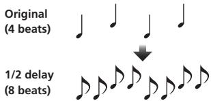
DELAY
A delay sound is output once according to the beat fraction set with the [BEAT , ] buttons.
When 1/2 beat delay sound is added, 4 beats become 8 beats.
| BEAT ▲ ▶ buttons (param- eter 1) | Use these to set a time delay of \( 1/8 - {16}/1 \) with respect to the time of one beat of the BPM. |
| TIME control (parameter 2) | Use this to set the delay time. 1 to 4000 (ms) |
| LEVEL/DEPTH control (parameter 3) | Use this to set the balance between the original sound and the delay sound. |
| X-PAD (parameter 4) | Use this to set the delay time. |
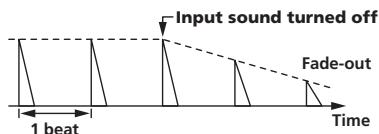
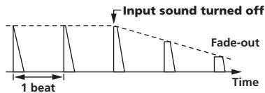
ECHO
A delay sound is output several times and gradually attenuated according to the beat fraction set with the [BEAT , ] buttons.
With 1/1 beat echoes, the delay sounds are faded out according to the track's tempo even after the input sound has been cut.
| BEAT ▲ ▶ buttons (param- eter 1) | Use these to set a time delay of \( 1/8 - {16}/1 \) with respect to the time of one beat of the BPM. |
| TIME control (parameter 2) | Use this to set the delay time. 1 to 4000 (ms) |
| LEVEL/DEPTH control (parameter 3) | Use this to set the balance between the original sound and the echo sound. |
| X-PAD (parameter 4) | Use this to set the delay time. |
SPIRAL
This function adds a reverberation effect to the input sound.
When the delay time is changed, the pitch changes simultaneously.
| BEAT ▲ ▶ buttons (param- eter 1) | Use these to set a time delay of \( 1/8 - {16}/1 \) with respect to the time of one beat of the BPM. |
| TIME control (parameter 2) | Use this to set the delay time. 10 to 4000 (ms) |
| LEVEL/DEPTH control (parameter 3) | Use this to set the balance between the original sound and the effect sound and to set the quantitative parameter. |
| X-PAD (parameter 4) | Use this to set the delay time. |
REVERB12
This function adds a reverberation effect to the input sound.
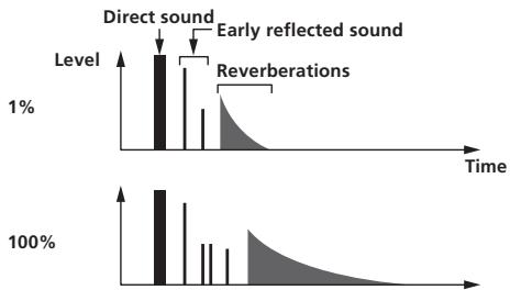
| BEAT ▲, ▲ buttons (param-eter 1) | Use these to set the extent of the reverberation effect, from 1 – 100 %. |
| TIME control (parameter 2) | Use this to set the degree of the reverb effect.1 – 100 (%) |
| LEVEL/DEPTH control (parameter 3) | Sets the balance between the original sound and the effect sound. |
| X-PAD (parameter 4) | Sets the filter's cut-off frequency. |
TRANS
The sound is cut according to the beat fraction set with the [BEAT ] buttons.
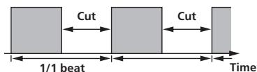
| BEAT ▲ ▶ buttons (param- eter 1) | Use these to set a cut time of 1/16 – 16/1 with respect to the time of one beat of the BPM. |
| TIME control (parameter 2) | Use this to set the effect time.10 to 16000 (ms) |
| LEVEL/DEPTH control (parameter 3) | Sets the balance between the original sound and the effect sound. |
| X-PAD (parameter 4) | This sets the cut time. |
FILTER
The filter's cutoff frequency changes according to the beat fraction set with the [BEAT ] buttons.
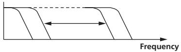
| BEAT ▲ ▶ buttons (param- eter 1) | Use these to set the cycle for moving the cut-off frequency as a time of 1/4 – 64/1 with respect to the time of one beat of the BPM. |
| TIME control (parameter 2) | Use this to set the cycle at which the cut-off frequency is moved. 10 to 32000 (ms) |
| LEVEL/DEPTH control (parameter 3) | The further the control is turned clockwise, the more the effect is stressed. |
| X-PAD (parameter 4) | The cycle at which the cut-off frequency is moved fluctuates finely. |
FLANGER
A 1-cycle flanger effect is produced according to the beat fraction set with the [BEAT , ] buttons.
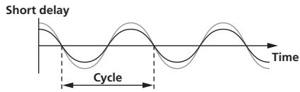
| BEAT ▲ ▶ buttons (param- eter 1) | Use these to set the 1/4 – 64/1 effect time with respect to the time of one beat of the BPM. |
| TIME control (parameter 2) | Use this to set the cycle by which the flanger effect moves. 10 to 32000 (ms) |
| LEVEL/DEPTH control (parameter 3) | The further the control is turned clockwise, the more the effect is stressed. When turned all the way counterclockwise, only the original sound is output. |
| X-PAD (parameter 4) | The cycle at which the flanger effect is moved fluctuates finely. |
PHASER
The phaser effect changes according to the beat fraction set with the [BEAT , ] buttons.
| BEAT ▲ ▲ buttons (param- eter 1) | Use these to set the cycle for moving the phaser effect as of time of 1/4 – 64/1 with respect to the time of one beat of the BPM. |
| TIME control (parameter 2) | This sets the cycle by which the phaser effect is moved. 10 to 32000 (ms) |
| LEVEL/DEPTH control (parameter 3) | The further the control is turned clockwise, the more the effect is stressed. When turned all the way counterclockwise, only the original sound is output. |
| X-PAD (parameter 4) | The cycle at which the phaser effect is moved fluctuates finely. |
ROBOT
The original sound is changed to a sound like one produced by a robot.
| BEAT ▲ ▶ buttons (param- eter 1) | Use these to set the degree of the effect sound, from -100 – 100 %. |
| TIME control (parameter 2) | Use this to set the degree of the effect sound. -100–100 (%) |
| LEVEL/DEPTH control (parameter 3) | Sets the balance between the original sound and the effect sound. |
| X-PAD (parameter 4) | This changes the degree of the effect sound. |
MELODIC
The mid-range of the sound being input at the point when the [ON/OFF] button is pressed is recorded, and the recorded sound is output according to the level of the sound being input.
| BEAT ▲▶ buttons (param-eter 1) | This sets the way in which the recorded sound is played. |
| TIME control (parameter 2) | This sets the way in which the recorded sound is played. |
| LEVEL/DEPTH control parameter 3) | This sets the balance between the original sound and the recorded sound. |
| X-PAD (parameter 4) | This sets the way in which the recorded sound is played. |
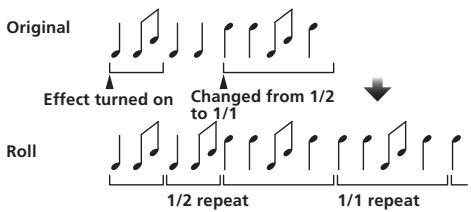
SLIP ROLL
The sound being input at the point when the [ON/OFF] is pressed is recorded, and the recorded sound is output repeatedly according to the beat fraction set with the [BEAT , ] buttons.
When the effect time changes, the input sound is recorded again.
| BEAT ▲, ▶ buttons (param- eter 1) | Use these to set an effect time of 1/16 – 16/1 with respect to the time of one beat of the BPM. |
| TIME control (parameter 2) | Use this to set the effect time.10 to 4000 (ms) |
| LEVEL/DEPTH control (parameter 3) | Use this to set the balance between the original sound and ROLL. |
| X-PAD (parameter 4) | Use this to set the effect time. |
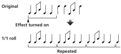
ROLL
The sound being input at the point when the [ON/OFF] is pressed is recorded, and the recorded sound is output repeatedly according to the beat fraction set with the [BEAT , ] buttons.
| BEAT ▲ ▶ buttons (param- eter 1) | Use these to set an effect time of 1/16 – 16/1 with respect to the time of one beat of the BPM. |
| TIME control (parameter 2) | Use this to set the effect time.10 to 4000 (ms) |
| LEVEL/DEPTH control (parameter 3) | Use this to set the balance between the original sound and ROLL. |
| X-PAD (parameter 4) | Use this to set the effect time. |
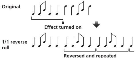
REV ROLL
The sound being input at the point when the [ON/OFF] button is pressed is recorded, and the recorded sound is reversed then output repeatedly according to the beat fraction set with the [BEAT , ] buttons.
| BEAT ▲ ▶ buttons (param- eter 1) | Use these to set an effect time of 1/16 – 16/1 with respect to the time of one beat of the BPM. |
| TIME control (parameter 2) | Use this to set the effect time.10 to 4000 (ms) |
| LEVEL/DEPTH control (parameter 3) | Use this to set the balance between the original sound and ROLL. |
| X-PAD (parameter 4) | Use this to set the effect time. |
SND/RTN (MIDI LFO)
Connect an external effector, etc., here.
By pressing the [LFO FORM (WAKE UP)] button, MIDI-compatible software and devices can be controlled using MIDI signals.
SND/RTN
Connect an external effector, etc., here.
| BEAT ▲,▶ buttons (param-eter 1) | — |
| TIME control (parameter 2) | — |
| LEVEL/DEPTH control (parameter 3) | This adjusts the sound level input to the [RETURN] terminal. |
| X-PAD (parameter 4) | — |
MIDI LFO
The MIDI signal (0 - 127) waveform is changed according to the track's tempo. The MIDI signal waveform pattern switches each time the [LFO FORM (WAKE UP)] button is pressed.
| BEAT ▲ ▶ buttons (param- eter 1) | Use these to set a waveform output time of 1/4 – 64/1 with respect to one beat of the BPM. |
| TIME control (parameter 2) | Use this to set the waveform output time. |
| LEVEL/DEPTH control (parameter 3) | — |
| X-PAD (parameter 4) | This changes the MIDI signal's waveform pattern. |
- When [MIDI LFO] is selected, the sound of the external effector connected to the [RETURN] terminal is not input.
If the sound of the channel you want to monitor is not output from the [MASTER] channel when [CF.A], [CF.B] or [MASTER] is selected with the [1, 2, 3, 4, MIC, CF.A, CF.B, MASTER] selector switch, the effect sound cannot be monitored even by pressing the [CUE] button for [BEAT EFFECTS].
If the effect is off, the effect sound cannot be monitored even by pressing the [CUE] button for [BEAT EFFECTS].
List of MIDI Messages
| Category | SW Name | SW Type | MIDI Messages | Trigger/Toggle | Notes | |||||
| MSB | LSB | |||||||||
| CH1 | TRIM | VR | Bn | 01 | dd | — | — | — | 0-127 | |
| HI | VR | Bn | 02 | dd | — | — | — | 0-127 | ||
| MID | VR | Bn | 03 | dd | — | — | — | 0-127 | ||
| LOW | VR | Bn | 04 | dd | — | — | — | 0-127 | ||
| COLOR | VR | Bn | 05 | dd | — | — | — | 0-127 | ||
| CUE | BTN | Bn | 46 | dd | — | — | Trigger/Toggle | OFF=0, ON=127 | ||
| Channel fader | VR | Bn | 11 | MSB | — | — | — | 0-127 | ||
| CROSS FADER ASSIGN | SW | Bn | 41 | dd | — | — | — | 0.64, 127 | ||
| CH2 | TRIM | VR | Bn | 06 | dd | — | — | — | 0-127 | |
| HI | VR | Bn | 07 | dd | — | — | — | 0-127 | ||
| MID | VR | Bn | 08 | dd | — | — | — | 0-127 | ||
| LOW | VR | Bn | 09 | dd | — | — | — | 0-127 | ||
| COLOR | VR | Bn | 0A | dd | — | — | — | 0-127 | ||
| CUE | BTN | Bn | 47 | dd | — | — | Trigger/Toggle | OFF=0, ON=127 | ||
| Channel fader | VR | Bn | 12 | MSB | — | — | — | 0-127 | ||
| CROSS FADER ASSIGN | SW | Bn | 42 | dd | — | — | — | 0.64, 127 | ||
| CH3 | TRIM | VR | Bn | 0C | dd | — | — | — | 0-127 | |
| HI | VR | Bn | 0E | dd | — | — | — | 0-127 | ||
| MID | VR | Bn | 0F | dd | — | — | — | 0-127 | ||
| LOW | VR | Bn | 15 | dd | — | — | — | 0-127 | ||
| COLOR | VR | Bn | 16 | dd | — | — | — | 0-127 | ||
| CUE | BTN | Bn | 48 | dd | — | — | Trigger/Toggle | OFF=0, ON=127 | ||
| Channel fader | VR | Bn | 13 | MSB | — | — | — | 0-127 | ||
| CROSS FADER ASSIGN | SW | Bn | 43 | dd | — | — | — | 0.64, 127 | ||
| CH4 | TRIM | VR | Bn | 50 | dd | — | — | — | 0-127 | |
| HI | VR | Bn | 51 | dd | — | — | — | 0-127 | ||
| MID | VR | Bn | 5C | dd | — | — | — | 0-127 | ||
| LOW | VR | Bn | 52 | dd | — | — | — | 0-127 | ||
| COLOR | VR | Bn | 53 | dd | — | — | — | 0-127 | ||
| CUE | BTN | Bn | 49 | dd | — | — | Trigger/Toggle | OFF=0, ON=127 | ||
| Channel fader | VR | Bn | 14 | MSB | — | — | — | 0-127 | ||
| CROSS FADER ASSIGN | SW | Bn | 44 | dd | — | — | — | 0.64, 127 | ||
| Crossfader | Crossfader | VR | Bn | 0B | MSB | — | — | — | 0-127 | |
| Fader curve | CH FADER (✓✓✓) | SW | Bn | 5E | dd | — | — | — | 0.64, 127 | |
| CROSS FADER (✗✗✗) | SW | Bn | 5F | dd | — | — | — | 0.64, 127 | ||
| Master | MASTER LEVEL | VR | Bn | 18 | dd | — | — | — | 0-127 | |
| BALANCE | VR | Bn | 17 | dd | — | — | — | 0-127 | ||
| CUE | BTN | Bn | 4A | dd | — | — | Trigger/Toggle | OFF=0, ON=127 | ||
| EQ CURVE (ISOLATOR. EQ) | SW | Bn | 21 | dd | — | — | — | 0.127 | ||
| BOOTH MONITOR | BOOTH MONITOR | VR | Bn | 19 | dd | — | — | — | 0-127 | |
| LINK | CUE | BTN | Bn | 73 | dd | — | — | Trigger/Toggle | OFF=0, ON=127 | |
| BEAT EFFECTS | ← | BTN | Bn | 4C | MSB | — | — | Trigger/Toggle | OFF=0, ON=127 | |
| → | BTN | Bn | 4D | — | — | — | Trigger/Toggle | OFF=0, ON=127 | ||
| AUTO/TAP | BTN | Bn | 45 | dd | — | — | Trigger/Toggle | OFF=0, ON=127 | ||
| TAP | BTN | Bn | 4E | dd | — | — | Trigger only | OFF=0, ON=127 | ||
| CUE | BTN | Bn | 4B | dd | — | — | Trigger/Toggle | OFF=0, ON=127 | ||
| EFFECT SELECT | DELAY | SW | Bn | 2A | dd | — | — | ② | OFF=0, ON=127 | |
| ECHO | SW | Bn | 37 | dd | — | — | ② | OFF=0, ON=127 | ||
| SPIRAL | SW | Bn | 2B | dd | — | — | ② | OFF=0, ON=127 | ||
| REVERB | SW | Bn | 36 | dd | — | — | ② | OFF=0, ON=127 | ||
| TRANS | SW | Bn | 35 | dd | — | — | ② | OFF=0, ON=127 | ||
| FILTER | SW | Bn | 3B | dd | — | — | ② | OFF=0, ON=127 | ||
| FLANGER | SW | Bn | 32 | dd | — | — | ② | OFF=0, ON=127 | ||
| PHASER | SW | Bn | 39 | dd | — | — | ② | OFF=0, ON=127 | ||
| ROBOT | SW | Bn | 33 | dd | — | — | ② | OFF=0, ON=127 | ||
| MELODIC | SW | Bn | 3D | dd | — | — | ② | OFF=0, ON=127 | ||
| SLIP ROLL | SW | Bn | 3A | dd | — | — | ② | OFF=0, ON=127 | ||
| ROLL | SW | Bn | 2E | dd | — | — | ② | OFF=0, ON=127 | ||
| REV ROLL | SW | Bn | 2F | dd | — | — | ② | OFF=0, ON=127 | ||
| SND/RTN (MIDI LFO) | SW | Bn | 3E | dd | — | — | ② | OFF=0, ON=127 | ||
| Category | SW Name | SW Type | MIDI Messages | Trigger/Toggle | Notes | ||||||
| MSB | LSB | ||||||||||
| BEAT EFFECTS | CH SELECT | CH1 | SW | Bn | 22 | dd | — | — | — | 2 | OFF=0, ON=127 |
| CH2 | SW | Bn | 23 | dd | — | — | — | 2 | OFF=0, ON=127 | ||
| CH3 | SW | Bn | 24 | dd | — | — | — | 2 | OFF=0, ON=127 | ||
| CH4 | SW | Bn | 25 | dd | — | — | — | 2 | OFF=0, ON=127 | ||
| MIC | SW | Bn | 26 | dd | — | — | — | 2 | OFF=0, ON=127 | ||
| CF.A | SW | Bn | 27 | dd | — | — | — | 2 | OFF=0, ON=127 | ||
| CF.B | SW | Bn | 28 | dd | — | — | — | 2 | OFF=0, ON=127 | ||
| MASTER | SW | Bn | 29 | dd | — | — | — | 2 | OFF=0, ON=127 | ||
| MIDI LFO | VR | Bn | 76 | dd | — | — | — | — | 0-127 | ||
| QUANTIZE | BTN | 9n | 76 | dd | — | — | — | Trigger/Toggle | — | ||
| TIME | SW | Bn | 0D | MSB | Bn | 2D | LSB | — | TIME value (When FLANGER,PHASER or FILTER is selected, thevalue is halved. When a negativevalue is selected, it is set to a posi-tive value.) | ||
| LEVEL/DEPTH | VR | Bn | 5B | dd | — | — | — | — | 0-127 | ||
| X-PAD | VR | Bn | 74 | dd | — | — | — | — | Sends the [X-PAD] position infor-mation. | ||
| ON/OFFX-PAD (touch)· When an effect other than[SND/RTN (MIDI LFO)] isselected at BEAT EFFECT | BTN | Bn | 72 | dd | — | — | — | 2 | OFF=0, ON=127 | ||
| ON/OFFX-PAD (touch)· When [SND/RTN (MIDILFO)] is selected at BEAT EFFECT | BTN | Bn | 40 | dd | — | — | — | 2 | OFF=0, ON=127 | ||
| MIC | HI | VR | Bn | 1E | dd | — | — | — | — | 0-127 | |
| LOW | VR | Bn | 1F | dd | — | — | — | — | 0-127 | ||
| SOUND COLORFX | NOISE | BTN | Bn | 55 | dd | — | — | — | Trigger/Toggle1 | OFF=0, ON=127 | |
| SPACE | BTN | Bn | 69 | dd | — | — | — | Trigger/Toggle1 | OFF=0, ON=127 | ||
| GATE/COMP | BTN | Bn | 6A | dd | — | — | — | Trigger/Toggle1 | OFF=0, ON=127 | ||
| DUB ECHO | BTN | Bn | 6B | dd | — | — | — | Trigger/Toggle1 | OFF=0, ON=127 | ||
| CRUSH | BTN | Bn | 56 | dd | — | — | — | Trigger/Toggle1 | OFF=0, ON=127 | ||
| FILTER | BTN | Bn | 57 | dd | — | — | — | Trigger/Toggle1 | OFF=0, ON=127 | ||
| Fader Start | Fader Start 1 | BTN | Bn | 58 | dd | — | — | — | Trigger/Toggle | OFF=0, ON=127 | |
| Fader Start 2 | BTN | Bn | 59 | dd | — | — | — | Trigger/Toggle | OFF=0, ON=127 | ||
| Fader Start 3 | BTN | Bn | 5A | dd | — | — | — | Trigger/Toggle | OFF=0, ON=127 | ||
| Fader Start 4 | BTN | Bn | 5D | dd | — | — | — | Trigger/Toggle | OFF=0, ON=127 | ||
| HEADPHONES | MIXING | VR | Bn | 1B | dd | — | — | — | — | 0-127 | |
| LEVEL | VR | Bn | 1A | dd | — | — | — | — | 0-127 | ||
| Timing Clock | — | F8 | — | — | — | — | — | — | — | ||
| Fader Start | Fader Start 1 | 9n | 66 | dd | — | — | — | — | BACK CUE = 0, PLAY = 127 | ||
| Fader Start 2 | 9n | 67 | dd | — | — | — | — | BACK CUE = 0, PLAY = 127 | |||
| Fader Start 3 | 9n | 68 | dd | — | — | — | — | BACK CUE = 0, PLAY = 127 | |||
| Fader Start 4 | 9n | 69 | dd | — | — | — | — | BACK CUE = 0, PLAY = 127 | |||
| MIDI | START | BTN | FA | — | — | — | — | — | — | — | |
| STOP | BTN | FC | — | — | — | — | — | — | — | ||
1 When turning one button on switches another button from on to off, MIDI on and off messages are sent from the two buttons.
When there is no button that switches off, only the MIDI on message is sent from the button that was pressed.
2 When switched from one position to another position, the MIDI ON and OFF signals are sent respectively from both positions.
- When the [START/STOP] button is pressed for over 1 second, MIDI messages corresponding to the positions of the buttons, faders and controls are sent in a bundle (Snapshot). The MIDI Snapshot sends all MIDI messages other than MIDI start and MIDI stop.
Changing the settings
1 Press the [ON/OFF (UTILITY)] button for over 1 second.
The [USER SETUP] mode setting screen is displayed.
- To display the [CLUB SETUP] mode setting screen, first turn this unit's power off, then press the [POWER] button while pressing the [ON/OFF (UTILITY)] button.
2 Press the [BEAT , ] button.
Select the setting item.
3 Press the [TAP] button.
The screen switches to the setting item's setting value change screen.
4 Press the [BEAT ,] button.
Change the setting value.
5 Press the [TAP] button.
Enter the setting value.
The previous screen reappears.
- To return to the previous screen without changing the settings, press the [QUANTIZE] button.
6 Press the [ON/OFF (UTILITY)] button.
Close the [USER SETUP] mode setting screen.
- To close the [CLUB SETUP] mode setting screen, press the [POWER] button to turn this unit's power off.
About the auto standby function
When [Auto Standby] is set to ON, the standby mode is set automatically if 4 hours pass with all of the conditions shown below met.
- That none of this unit's buttons or controls are operated.
- That no audio signals of -10 dB or greater are input to this unit's input terminals.
- That no PRO DJ LINK connections are made.
- When the [LFO FORM (WAKE UP)] button is pressed, the standby mode is canceled.
- This unit is shipped with the auto standby function turned on. If you do not want to use the auto standby function, set [Auto Standby] to [OFF].
About the talk over function
The talk over function has the two modes described below.
- [ADV] (advanced talk over): The mid-range only of the sound of channels other than the [MIC] channel is attenuated according to the [Talk Over LEVEL] setting value and output.
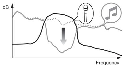
- [NOR] (normal talk over): The sound of channels other than the [MIC] channel is attenuated according to the [Talk Over LEVEL] setting value and output.
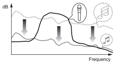
Setting preferences
*: Setting upon purchase
| Mode | Options settings | Screen display | Setting value | Descriptions |
| USER SETUP | Fader Start | F.S. | ON, OFF* | Turns the fader start function on and off for all DJ players connected to the [LINK] terminals. |
| MIDI CH | MIDI CH | 1* to 16 | Sets the MIDI channel. | |
| MIDI Button Type | MIDI BT | TGL*, TRG | Selects the MIDI signal transmission mode, [TGL (TOGGLE)] or [TRG (TRIGGER)]. | |
| Talk Over Mode | TLK MOD | ADV*, NOR | Selects the talk over function's mode, [ADV(ADVANCED)] or [NOR(NORMAL)]. | |
| Talk Over LEVEL | TLK LVL | -6 dB, -12 dB, -18 dB*, -24 dB | Sets the talk over function's sound attenuation level. | |
| CLUB SETUP | Digital Master Out Level | DOUT LV | -19 dB*, -15 dB, -10 dB, -5 dB | Sets the maximum level of the sound output from the [DIGITAL MASTER OUT] terminals. |
| Digital Master Out Sampling Rate | DOUT FS | 48 kHz, 96 kHz* | Sets the digital signal's sampling rate. | |
| MASTER ATT. | MST ATT | -6 dB, -3 dB, 0 dB* | Sets the attenuation level of the sound output from the [MASTER1] and [MASTER2] terminals. | |
| Auto Standby | AUTOSTB | ON*, OFF | Turns the auto standby function on and off. | |
| Mic Output To Booth Monitor | MIC BTH | ON*, OFF | Sets whether or not to output the microphone's audio signals from [BOOTH] terminals. | |
| PC UTILITY | PC UTLY | ON*, OFF | Sets whether or not to launch the computer's setting utility software automatically when a USB cable is connected. | |
| Factory Reset | INITIAL | YES, NO* | Restores all the settings to their factory defaults. |
1: Note that the output sound may be distorted even if the master level indicator does not light up to the very top.
Additional information
Troubleshooting
Incorrect operation is often mistaken for trouble or malfunction. If you think that there is something wrong with this component, check the points below. Sometimes the trouble may lie in another component. Inspect the other components and electrical appliances being used. If the trouble cannot be rectified after checking the items below, ask your nearest Pioneer authorized service center or your dealer to carry out repair work.
The player may not operate properly due to static electricity or other external influences. In such cases, normal operation may be restored by unplugging the power cord then plugging it back in.
| Problem | Check | Remedy |
| The power is not turned on. | Is the power cord properly connected? | Plug in the power cord to an AC outlet. |
| No sound or small sound. | Is the [DIGITAL, CD/LINE, PHONO, LINE, USB */] selector switch set to the proper position? | Turn the [DIGITAL, CD/LINE, PHONO, LINE, USB */] selector switch to switch to the channel's input source. (page 13) |
| Are the connection cables properly connected? | Connect the connection cables properly. (page 7) | |
| Are the terminals and plugs dirty? | Clean the terminals and plugs before making connections. | |
| Is [MASTER ATT.] set to [-6 dB], etc.? | At the [USER SETUP] screen, switch [MASTER ATT]. (page 22) | |
| Digital sound cannot be output. | Is the digital audio output's sampling frequency (fs) suited for the specifications of the connected device? | On the [CLUB SETUP] screen, set [Digital Master Out Sampling Rate] according to the specifications of the connected equipment. (page 22) |
| Distorted sound. | Is the sound level output from the [MASTER] channel appropriately set? | Adjust the [MASTER LEVEL] control so that the master channel level indicator lights at around [0 dB] at the peak level. (page 13) |
| Set [MASTER ATT.] to [-3 dB] or [-6 dB]. (page 22) | ||
| Is the level of audio input to each channel properly set? | Adjust the [TRIM] control so that the channel level indicator lights at about [0 dB] at the peak level. (page 13) | |
| Can't crossfade. | Are the CROSS FADER ASSIGN (A, THRU, B) selector switches properly set? | Set the [CROSS FADER ASSIGN (A, THRU, B)] selector switches for the different channels properly. (page 13) |
| Can't fader start a DJ player. | Is [FADER START] set to [OFF]? | At the [USER SETUP] screen, set [FADER START] to [ON]. (page 22) |
| Is the DJ player properly connected to the [LINK] terminal? | Connect the DJ player to the [LINK] terminal properly using a LAN cable. (page 7) | |
| Are the audio cables properly connected? | Connect this unit's audio input terminals and the DJ player's audio output terminals by audio cable. (page 7) | |
| Is the DJ player's player number properly set? | Set the DJ player's player number to the same number as the channel to which the audio cable is connected. | |
| [BEAT EFFECTS] does not work. | Is the [1, 2, 3, 4, MIC, C.F.A, C.F.B, MASTER] selector switch properly set? | Turn the [1, 2, 3, 4, MIC, C.F.A, C.F.B, MASTER] selector switch to select the channel to which you want to apply the effect. |
| [SOUND COLOR FX] does not work. | Is the [COLOR] control set to an appropriate position? | Turn the [COLOR] control clockwise or counterclockwise. (page 14) |
| Can't use an external effector. | Is the [ON/OFF] button for [BEAT EFFECTS] set to [ON]? | Press the [ON/OFF] button for [BEAT EFFECTS] to set [SND/RTN] to [ON]. (page 15) |
| Is the external effector properly connected to the [SEND] or [RETURN] terminal? | Connect the external effector to the [SEND] and [RETURN] terminals. (page 7) | |
| Distorted sound from an external effector. | Is the external effector's audio output level set to an appropriate level? | Adjust the external effector's audio output level. |
| Tempo (BPM) cannot be measured or measurement value of tempo (BPM) is implausible. | Is the audio input level too high or too low? | Adjust the [TRIM] control so that the channel level indicator lights at about [0 dB] at the peak level. (page 13) |
| For some tracks, it may not be possible to measure the tempo (BPM). Use the [TAP] button to input the tempo manually. (page 15) | ||
| Measured tempo (BPM) differs from tempo indicated on CD. | — | The values may differ slightly due to the different ways in which the BPM is measured. There is no need to make any corrections. |
| MIDI sequencer does not synchronize. | Is the MIDI sequencer's sync mode set to Slave? | Set the MIDI sequencer's sync mode to Slave. |
| Does the MIDI sequencer you are using support MIDI timing clocks? | MIDI sequencers not supporting MIDI timing clocks cannot be synchronized. | |
| MIDI control does not work. | Is the MIDI channel turned on? | Press the [ON/OFF] button for [MIDI]. (Operating DJ software using the MIDI function on page 16) |
| Are the MIDI settings properly set? | To operate DJ software with this unit, this unit's MIDI messages must be assigned to the DJ software you are using. For instructions on assigning messages, see your DJ software's operating instructions. | |
| This unit is not recognized after it has been connected to a computer.USB indicator is off or flashing. | Is the driver software properly installed on your computer? | Install the driver software. If it is already installed, reinstall it. (page 8) |
| Sound of a computer cannot be output from this unit. | Are this unit and computer properly connected? | Connect this unit and computer using a USB cable. (page 8) |
| Are the audio output device settings properly set? | Select this unit with the audio output device settings. For instructions on making settings for your application, see your application's operating instructions. | |
| Is the [DIGITAL, CD/LINE, PHONO, LINE, USB */] selector switch set to the proper position? | Set the [DIGITAL, CD/LINE, PHONO, LINE, USB */] selector switch to the [USB */] position. (page 13) | |
| Effect sound cannot be monitored even when the [CUE] button for [BEAT EFFECTS] is pressed. | — | The circuit that generates the echo for the [ECHO], [REVERB], [ROLL], [SLIP ROLL] and [REV ROLL] effect sounds is positioned after the effect circuit, so the effect sound cannot be monitored. This is not a malfunction. |
| Sound is distorted when an analog player is connected to this unit's [PHONO] terminals. | Have you connected an analog player with a built-in phono equalizer? | For analog players with built-in phono equalizers, connect the player to the [CD/LINE] or [LINE] terminals. (page 7) |
| Or, lighting of the channel level indicator does not change even when the [TRIM] control is turned. | Is an audio interface for computers connected between the analog player and this unit? | If the analog player with built-in phono equalizer has a PHONO/LINE selector switch, switch it to PHONO. |
| If the audio interface for computers has a line level output, connect it to the [CD/LINE] or [LINE] terminal. (page 7) | ||
| If the analog player has a PHONO/LINE selector switch, switch it to PHONO. |
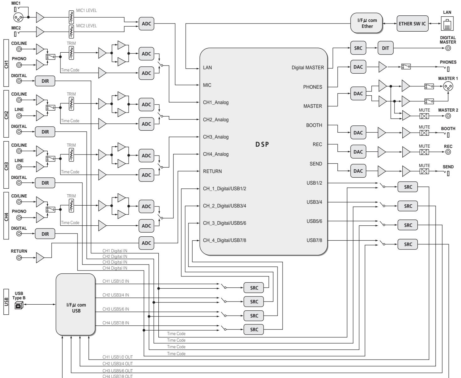
Block Diagram
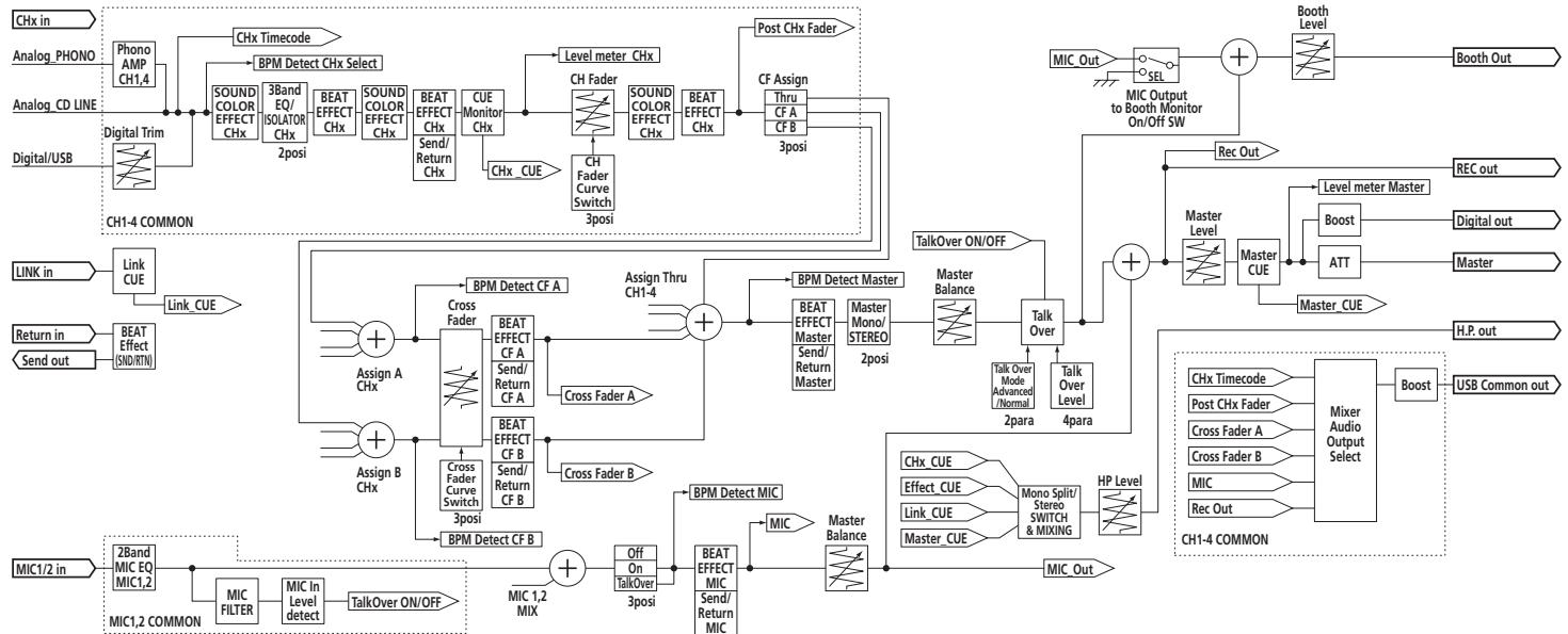
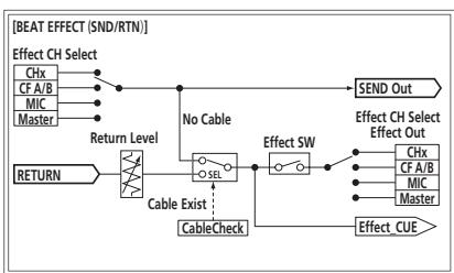
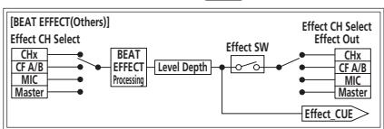
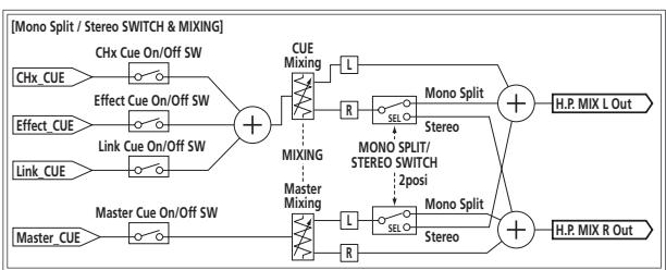
Disclaimer
- Pioneer and rekordbox are trademarks or registered trademarks of the Pioneer Corporation.
- Microsoft® , Windows Vista®, and Windows® are either registered trademarks or trademarks of Microsoft Corporation in the United States and/or other countries.
Apple, Macintosh and Mac OS are trademarks of Apple Inc., registered in the U.S. and other countries.
ASIO is a trademark of Steinberg Media Technologies GmbH.
The names of companies and products mentioned herein are the trademarks of their respective owners.
Specifications
General
Power requirements AC 220 V to 240 V, 50 Hz/60 Hz
Power consumption. 41 W
Power consumption (standby) .0.4 W
Main unit weight 7.1 kg
Max. external dimensions ......331 mm (width) x 107.9 mm (height) x 409 mm (depth)
Tolerable operating temperature +5^ to +35^
Tolerable operating humidity . 5 % to 85% (no condensation)
Audio Section
Sampling rate 96 kHz
MASTER D/A converter 32 bits
Other A/D and D/A converters 24 bits
Frequency characteristic
CD/LINE 20 Hz to 20 kHz
S/N ratio (rated output)
PHONO 88 dB
CD/LINE 105 dB
MIC1, MIC2 84 dB
Total harmonic distortion (CD/LINE - MASTER1) 0.005 %
Standard input level / Input impedance
PHONO .52 dBu/47 kΩ
CD/LINE -12 dBu/47 kΩ
MIC1 .52 dBu/8 kΩ
MIC2 .52 dBu/12 kΩ
RETURN. -12 dBu/47 kΩ
Standard output level / Load impedance / Output impedance
MASTER1 +8dBu / 10k /5 or lower
MASTER2 +2dBu / 10k /22 or lower
REC OUT. -8 dBu/10 kΩ/22 Ω or lower
BOOTH +8dBu / 10k /1k or lower
SEND. -12 dBu/10 kΩ/1 kΩ or lower
PHONES +8.5 dBu/32 Ω/1 Ω or lower
Rated output level / Load impedance
MASTER1. +26dBu / 10k
MASTER2 +22dBu / 10k
Crosstalk (LINE) 82 dB
Channel equalizer characteristic
HI. -26 dB to +6 dB (13 kHz)
MID -26 dB to +6 dB (1 kHz)
LOW. 26 dB to +6 dB (70 Hz)
Microphone equalizer characteristic
HI. -12 dB to +12 dB (10 kHz)
LOW. -12 dB to +12 dB (100 Hz)
Input / Output terminals
PHONO input terminal
RCA pin jack. 2 sets
CD/LINE input terminal
RCA pin jacks. 4 sets
LINE input terminal
RCA pin jack. 2 sets
MIC1 input terminal
XLR connector/phone jack (6.3 mm) 1 set
MIC2 input terminal
Phone jack (6.3 mm) 1 set
RETURN Input terminals
Phone jack (6.3 mm) 1 set
DIGITAL IN coaxial input terminal
RCA pin jacks. 4 sets
MASTER output terminal
XLR connector 1 set
RCA pin jacks 1 set
BOOTH output terminal
Phone jack (6.3 mm) 1 set
REC OUT output terminal
RCA pin jacks 1 set
SEND output terminal
Phone jack (6.3 mm) 1 set
DIGITAL MASTER OUT coaxial output terminal RCA pin jacks. 1 set
MIDI OUT terminal 5PDIN. 1 set
PHONES output terminal Stereo phone jack (6.3 mm) 1 set
USB terminal B type. 1 set
LINK terminal LAN terminal (100Base-TX). 1 set
- The specifications and design of this product are subject to change without notice.
Published by Pioneer Corporation. Copyright © 2011 Pioneer Corporation. All rights reserved.
IMPORTANT

[LFO FORM (WAKE UP)].
[LFO FORM (WAKE UP)].
WAARSCHUWING NETSNOER
LEVEL/DEPTH]instelling
Lasmerican PRO DJ LINK is a joint venture company established by the U.S. Department of State and the National Institute of Science and Technology (NSIT) in 1984. The NSIT is a state-of-the-art research institute that focuses on the study of the physics, chemistry, and biology of life and nature. Its main research area is the study of the structure and dynamics of living systems.
Para poder detailles de PRO DJ LINK,vea Acerca de PRO DJ LINK en la pagina 15.
DISPOSICION ESTANDAR
Usted accepts that each of the four countries has a present contract with the U.S. and Canada. The contract includes a guarantee for the U.S. to provide the necessary financial support for the U.S. to implement the U.S. program in the United States.
5 Terminación
MEPbI IPEIOCTOPOXHOCTN IPN OBaPAUeHn C CETEBbIM UHYPOM
Держпге сerteвошур 3а ВИнку. He Bытackиьге вИлку,В38aBшись 3a WHyp,и HNKOrda He KacaITeCb certeBOrO shHpya,ecnB Baun pykn BnaJxHbIe,TAK KaK 3TO MOKeT npIBeCTN K KOPOTKOMy 3aMbIkaHInO nIN nopaxHeHIO 3neKTPnueCckm TOKOM. He CTaBbTe annapat,пpeDmetbI Me6eInu T.D. Na ceteBOw shHyp, He 3aЖIMaIte erO. He 3aBra3bIbaIte y3IOB Ha shHype n He CBra3bIbaIte erO c DpyHMn WHypamn. CerteBbIe shHypbldoJXhbl JekTaT,чTO6bl Ha HIX HeJIb3a 6bIINO hAcTynITb. ПOBpeKdEHHbI certeBOW shHyp MoKeT ctaTb prUnHNo BO3HNKHOBEHn IOXapa nIN nopazItb Bac 3neKTPnueCckm TOKOM. BpeMЯ OВpeMeHn pOBePraIte certeBOw shHyp. B cnyuae 0bHapUxehnnoBpeXdEHnno OpaTITcEsb 3a ZAMHoB B 6bnkaiuOn oФnuaJIbHbI cepBnChbI ceHTp ФирмБ PIONEER nIN K BaWeMy dInepy.
S002*A1Ru

Ecnn Bbl jenae t ytnn3npoBaTb daHnoe n3dene, He Bbl6paCbBAIte ero BMecTe C obhHbIM 6blTOBm MycopoM. CyueCTbyET OTdeNbH aCyTeMa c6opba NCOpJb3OBAHHbIX 3NeKTPoHHbIX n3dEJIIN B COOTBeTCTBm C 3aKHOdaTeJIbCTBOM, KOTOPa IpeIPOIrae COOTBeTCTByIOUcE o6paUeHne, Bo3Bpat N nepepaBoTky.
YactbIe KInHeTb-B CtpaHax-UneHax EC, B WBeIzapmN HOpBErnMOnyT 6ecIpaTHo BO3BpaaTaB NcPONb3OBAHHbIe 3JeKTPoHHbIe n3dJIIN B COOTBETCTByUOJIe nyHKtbl c6opa IIN dIIpepy (pnp NKynke cxOJHO HOBOr n3dJIIN).
B ctpaHax, He nepeuicneHHbix Bblse, Iy noluyehn HOpmaun O npabInhbx cnocobax ytniHaun o6paauTeB CootbetCTByouane ypcexdenn.
IocTynar TAKIM O6pa3OM, Bbl MoKTe 6b1b YBepHb I TOM, UTO yTuIN3npyEmbl npOyKT 6dyet COOTBeTCTByIOUM o6pa3OM o6pa60tAn, npeDaH B COOTBeTCTByIOU pNHT I nepepa60TaH 6e3 BO3MOxHBx HeraTnBbX IOcNECTBm I Dn OkpykaIoUe Cpebl I 3dOpOB8JIIOJe.
K058b_A1_Ru
Copepkanne
Kak cIeJyTe UHTaTb daHHepykoBoCTBO
Ha3BaHnI 3KpaHOB, MeHIO KHNOK B DaHHOM pyKOBOIDCTBe yKa3aHb I CkO6KaX.
(Haipnimep, KaHaJI [MASTER], MeHIO [ON/OFF], [File])
01 Do hauana
CboBCTBa 5
KOMJIeKT noCTaBKn 5
102 PtoKnIOUeyHn
3aHnaHb. 6
3 TepMHaJIbI PHONO (ctp. 7)
ПлдклочитК Выхонomyпоигрьваюшему yctpoiCTBY (c rOlOBKо 3Bykoc-HimataTea MM). He BBOДNTe CINHaJIbI JINHeHOrO yPobHЯ.
Дяпюклоченя усторьтва К Термнанам [PHONO] n3BNEKNTe BCTaBNeHHyOВ Термнанлы 3amblkaioош WtbyipbKOble BnJIKN.
Bo n36exaHne BHeIe HcMybCTaBbTe DaHbIe 3aMbKaIOUe IITbIpbKOBbIe BnIKN B TepmHaJIbI [PHONO], KOrda K HmM HHyero He NOpKnIOuyeHO.
4 TepMHaJIbI CD/LINE (ctp. 7)
IopKJIOUHTe K DJ npOIRpbIBaTeJIIO IIN BbIXoHOMy KOMnHOHeTMy IINHeHOrO ypOBH.
5 TepmHaJ SIGNAL GND (ctp. 7)
IopknHouHte cOda npBOoD 3aemLeHnaHAnorOBOro npOnrpBbATEJ.3To n03BONIT yMeHbShTb Shm npn PNOKnHcHEnn aHaNOROBOro npOnrpBbATEJ.
6 TepmHaJIbI LINE (cTp. 7)
IopKJIOUHTe K KACCETHOMy MaHHTOΦOHy IIN BbIXoHOMy KOMHOHeTy JInHei-HOrO yOpBHa.
7 TepMNHaJI MIC2 (ctp. 7)
IoiKnIOUHTe K MmKpOoHou.
8 TepmHaJI MIDI OUT (ctp. 7)
10 TepmunhaJ DIGITAL IN (ctp. 7)
IopKIOHHTeN K cIpPobBIM KOAKcnaJIbHbIM BbIXoNDbIM TepMnHaam Ha DJ npOnrPbIbATEJnx,Д.3ByaHHe MOKeT Ha MfHOBeHne IppeBbTaBcR prn nepeKIIuOHeHH YactOToI DnCKPeTn3aCm BbIXoNDHO KaHaJa.
11 TepMNHaJIbI DIGITAL MASTER OUT (ctp. 7)
BbIOd ayDIOOHNHOOCHBOHO KAHAJa.
12 TepMNHaJLINK (ctp.7)
Плкюпгд nx K tepmaналam LINK ha DJ npoimрьвateяx Pioneerинк npotram LAN ha komlbpoTeapcx cystalOBnHbIMrekordbox (PRO DJ LINK). Дяп полkuоченя Heckonblkux yctpoiCTB nCNoIb3yTe KOHcHTpaTop- kOMMyTaTOp (npOdaetc rOdJIbHo).
IcnoIb3yIte KOHcEHTpaTOp-KOMMyTaTOp, COBMeCTmblc 100Base-TX. HeKoTOpble KOHcEHTpaTOp-KOMMyTaTOp bMOrYT He cpa6aTBaTb COOTBeTCTByUOzIM O6pa3OM.
13 TepmHaJIbI BOOTH (ctp. 7)
BbIXOHBIE TepMNHaJIbI dJa MOHITOpa KaBInHKn dN-DJKeA, COBMeCTMlbE C cMMMeTpnuhMb IIN HeCMMMeTpnuhMb BbIXoOM dJa KOHNHeKTopa TRS.
14 TepMNHaJIbI REC OUT (ctp. 7)
3TO BIXOHOI TepMNHaI dIa3aIINCI.
15 TepMNHaJIbI MASTER2 (ctp. 7)
IopKJIIOUHTe KUCNJINTELO MOUHOCTN,dp.
16 TepMNHaJIbI MASTER1 (ctp. 7)
IopKnIOUHTe KcunNTeHMOuHOCn,dp.
17 TepMNHaJIbI SEND (ctp. 7)
Поdkлioчп Te KВхODHMy TepMHAny BHeшнero 3фф ekTopa. Korda noI-KIIOUeH ToIbKO KaHaN [L (MONO)], BbIbOДNTcra ToIbKO MOHOΦOHnueckn aydINOcINrHaN.
18 AC IN
MepbI npeOCTOpOxHocTH no yCTaHOBKe
-Перед установский поportаммого драиьера оtmлочи петаиме данноаappapataи отоeingite USK abeBJ ot danhhoro apnapataи KMblbotepa.
Подкюнец дан Horо apannapata K komblotepу 6e3 npedbapntelho yctahOBKN nporpamMHoro dpaHbepa moKet npBecTu K c6oMa Ha komblotepe B 3aBNCIMOCTN OT CNTeMHOcpebl.
- Ecnu yctahOBka 6bIa npepBaH a Bo Bpemy yCTaHBOKn, 3aHO BO pOIN3BcENTe npocecc yctahOBKn c Camoro Na, CneDy CneDyuOe nnpozeype.
- Ipeed yctaHOBKO nateHTOBAHHOR nporpaMMHOr OpaBepa daHHOR annapata BHMaTeJIbHO npouTHe NueH3IOHHOe CornaeHne c KOHeuHbIM nonb3OBaTeIeM.
64-pa3pndnaBepcna WindowsXP Professional He noDepxNbaetc.
7 BbInonHnTe yctaHOBky, cJeDy HNCTpyKzmaH Ha 3kpaHe.
3 INdkaTop NOkNoueHn USB
BbCbeuBaetc npo o6meHe CunHanamn C KOMnbTeporm.
4 PyuKa MIC1 LEVEL (ctp. 15)
Perynipyet ypOeHb 3ByuHaHn, BbIbOIMoRo O T KaHaHa [MIC1].
5 PyuKa MIC2 LEVEL (ctp. 15)
PerynpyeT ypoBeHb 3BvHaHnA, BbIODmOro O T KaHaJa [MIC2].
6 Puykn EQ (HI, LOW) (ctp. 15)
OHIpeYIpyIOTToHaJIbHocTbKaHaIIOB [MIC1]n [MIC2].
7 CeJIeKTopHbI nepeKlnUcaTeJb OFF, ON, TALK OVER (ctp. 15)
Bknioyae/ToknIOyae Mkpooh
8 Khonkn SOUND COLOR FX (ctp. 15)
OHN BKNIOUaHOT/OTKNIIOUaHOT 3ΦΦeKTBI SOUND COLOR FX.
9 KhoNKn CUE (ctp. 14)
Haxkmtte KhoNky(u) [CUE]Дя KaHaJa(OB), KOtOpbI(bIe) XOTnTe KOHTpOJInpoBaTb.
10 KhoNkFADER START (1,2,3,4) (ctp. 14)
OHN BKNIOaOT/OKNIQUaOT fynKcIIO 3aNyCa c NOMOsbI OeIepa.
11 CeJIeKToPbI nepeKluOaTeIb MONo SPLIT,STEREO (cTp. 14)
Ipeeknouaet cnoocb pacnpedeHnKoHTpOIpyEmo3ByaHn, BbIOmmoTO HTayuHKnOB.
2 Pyukn MIXING (cTp. 14)
Они Perулирют 6baHc KOHTpOblHOro yPOBHЯ ГРМКоCTN 3BvuaHЯ KaHaNoB, Дя КOTopbIx HaxaTa KHNka [CUE]и 3BvuaHЯ KaHaJa [MASTER].
13 PyuKa LEVEL (ctp. 14)
PerynpyeT ypoBeHb 3ByuHaHn, BbIODMoO OT HayuHnKOB.
14 TepmHaI PHONES (cTp. 14)
IopdkJIOUHTe cOJa hauuHnKn.
15 ИndikaTop aydnoBxoja USB
BbCBeuBaetc npn noCTyIeHm 3ByaHnO T KOMlbIOTepa Ha pa3nHbIe KaHaJIbl.
16 CeJIeKTopHbI nepeKJIIOuAteJIb DIGITAL, CD/LINE, PHONO, LINE, USB */* (ctp. 14)
BbIbePte IcTOnHnK BxOJa KaKdOro KaHaJna I3 KOMIOHeHToB, nOdkJIIOueHHbIX K daHOMy annapaTy.
17 PyuKa TRIM (ctp. 14)
Perynipyet ypOBeHb ayDIOscIHaJIoB, noCTypaIOxH Na KaKdI KAnJ.
18 PyuK EQ/ISO (HI, MID, LOW) (ctp. 14)
Oh nperynnpuyt KaueCTBO 3ByuHaHna pa3nHybIX KaHaIIOB.
19 UHdukaTop ypoBHa KaHaJa (ctp. 14)
OToBpaKaet yPoBeHb 3ByuHaHnPa3nUHbIX KaHaNoB Do npOnyScKaHn Ype3 feiDebpI KaHaNoB.
20 Puyknc COLOR (cTp. 15)
Ipeeknloaet pexm n3mepehna BPM.
41 CeJIeKTopHbI NpeKJIuOaTeJb DELAY, ECHO, SPIRAL, REVERB, TRANS, FILTER, FLANGER, PHASER, ROBOT, MELODIC, SLIP ROLL, ROLL, REV ROLL, SND/RTN (MIDI LFO) (cTp. 16)
Ipeeknouaet Tn3ofoeKaBEAT EFFECT.
2 CeJIeKTopHbI IpepeKIIuOaTeIb 1, 2, 3, 4, MIC, CF.A, CF.B, MASTER (ctp. 16)
Ipeeknouaet kaHan, dny KOtOporo npImeHreTcBEAT EFFECT.
43 Pyuka TIME (cTp. 16)
OtperyuynyTe BpeMeHHo napametp BEAT EFFECT.
44 PyuKa LEVEL/DEPTH (cTp. 16)
Perynpyet KOnuYeCTBeHHbI npaMeTp BEAT EFFECT.
45 Khoonka ON/OFF (cTp. 16)
BkIouaet/OTknIouaet yHKmIO BEAT EFFECT.
He npimehaIte n3JInuHIO Cnny npn BbITraBauHn peJeepa KaHana npyek Kpoccepepa.PyuKHe MOrTy n3BLeKaTcR nonHoCTbU. CnIbHoe BbITraBauHne puYek MOKeT pnpBeCTN K nONOMKe annapata.
OchOBHoe ynpabJIeHne
BbIBoD 3ByuHaHnA
1 HaxMMTe KhoNky [POwER].
BkHIOUHTe NITaHHe DaHHoro annapata.
2 BpauaTe celeKTopbI nepeKJIouaTeIb [DIGITAL, CD/LINE, PHONO, LINE, USB */*].
BbIepnTe nCTOuHnK BxOa dIpa3nUHbIX KaHaIOB u3 yCTpOJCTB, POnkIHOeHNbIX K daHHOMy annapaty.
[DIGITAL]: Bыбор DJ поирьоватя, подклочен Horо К тершалam [DIGITAL].
- [PHONO]: Bыбораанoroboro npoɪrpьiBaTeЯ, noДклюechнoroК.TepMn-Haʌm[PHONO].
- [CD/LINE], [LINE]: Вьбор касстHoro Магнитофona Или CD-npoinрьвateя, покlioуechногК Термиhanam [LINE].
- [USB /]: Bыбор 3ByaHЯ OT KOMnbHTopepa, поДкПluЧeHHOrO K nOpTy [USB].
3 BpaaaiTe pyky [TRIM].
Perynipyet ypoBeHb ayDIOcRHaNoB, noCTynAIOxN Ha kaXdbI KaHaN. KordaayIOcRHaNbI hADnEkaMIM oBa3OM noCTyNAOT Ha hyKhbI KaHaN, BbICBeuBaTeCn IHdNKaTOp yPoBHr COOTBeTCTByUoIero KaHaN.
4 YctahOBITE fepaKaHaHa HbHTpeHHee nOIOXeHne
PerynpyetyuOBeH ayDIOscnHaNoB, BbIBoDjaXxCBA kKaJdOM kaHaJe.
5 NepekJIIOUHTe CeJIeKTopHbI nepeKJIIOUaTeIb [CROSS FADER ASSIGN (A, THRU, B)].
IpekeKIOUaet MeCTO BbIbOa KaJzDOrO KaHana.
[A]:Ha3HaaetaH ha [A] (JIeBbI) KpOcCpeIepa.
[B]: Ha3NaueTaHa [B] (npaBbI) KpocccpeIepa.
- [THRU]: BbIbepuTe DaHHyU NoCTpOryK, KOrDa He THe Heo6xOIMoCTn IcNoIb3OBAt b KpocCpeJdep. (CunHabI He npoxOarT uepe3 KpocCpeJdep.)
6 HactpoTe Kpocccpeidep
B daHno onepaunn Ht Heo6xOIMoCTn, KOrDa ceJeKToPbI nepeKJIOuateJIb [CROSS FADER ASSIGN (A, THRU, B)] yctaHOBneHa [THRU].
7 BpauaTe pyky [MASTER LEVEL].
AydnoCnHaJIb BiBIOaTcO TepMHaIob [MASTER1] n [MASTER2].
BbCbeuBaetnHdNkaTOp KOHTpOJIbHOrO yPoBHa.
PergunpoBka KaueCTBa 3ByuHaHna
BpaaTe pyckn [EQ/ISO (HI, MID, LOW)] dans pa3nHbIX kaHaJOB.
Пдиапазону 3ычанne,peryларуемOMу кадьIM peryларTopOM,CMOTpTe TexнчесnéхаразкетерпстNiHa ctrp.26.
Пеклоченhoe Функции ручек [EQ/ISO (HI, MID, LOW)]
Ipeeknouhte celenktophni nepeeknouatelb [EQ CURVE (ISOLATOR, EQ)].
- [ISOLATOR]: Cpa6aTbIbAET B KaueCTBe pa3beINHITeJIa.
—[EQ]:BkIIOUeHaФyHKUma3Kbana3epa.
KoHTpoJIb 3ByaHnIc NOMOuIbIO HayuHnKOB
1 PoiKJIIOUHTe HayuHnKn K rHe3dy [PHONES]
2 HaxmTe KhoNky(n) [CUE] nla KaHaJaOB), KOToPbI(bie) XOTnTe KOHTpOJInpoBaTb.
3 NepeKJIIOUHTe ceJIeKTopHbI nepeKJIIOUaTeIb [MONO SPLIT, STEREO].
[MONOSPLIT]: 3ByuHHe KaHaNoB,ДЯ KOTOpbIX HauKaTa[CUE], BbyIO-DIITcR O T IeBOrO KaHaNlBa BixOJa HayuHnIKoB, a 3ByuHHe KaHaNlA [MASTER] BbyIOHTcR O T npaBO rO KaHaJa.
- [STEREO]: 3ByuHaHne KaHaNoB, ДЯ КOTopbIx HauKaTa KHOIIka [CUE], BblBO-DITcra OT HayUHNKOB BCTepeOoHOnueCeKOM peKIMe.
4 BpaaaIte pyuKy [MIXING].
2 YcTaHOBnTe CeJIeKTopHbI InepeKlnOuTaTeIb [OFF, ON, TALK OVER] Ha [ON] nIIn [TALK OVER].
BpaaTe pyuKn KaHaJIOB [MIC] [EQ (HI, LOW)].
IpeekJIOUHTe celenKTopHbI nepeekJIOUaTeIb [MONO,STEREO].
— [MONO]: BbIbOaNT MOHOΦoHnueckn aYdIoNcIrHaJI.
- [STEREO]: Bыбоит CTepoфонческий aydnoсгhan.
PeryunnpovkaJI/II6aJahcaydnocnHaJa
Mожно отperiуліровасы leвий/nравьй баланс 3ычаня, bывodимого от тер'mиналов [MASTER1], [MASTER2], [BOOTH], [REC OUT], [PHONES], [DIGITAL MASTER OUT] n [USB].
-ДяperуларовиЗвун,在BbIOIMOROOTepMnHaIOB[USB]BbIepePte [RECOUT]B[MixerAudioOutput]ByTNITHeHacTPOKN.
1 YctaHOBtE CeIeKToPbHn IpeKeIIOuTaTeNb [MONO, STEREo] Ha [STEREO].
2 BpaaaTe pyky [BALANCE].
BaIaHc IeBoH/npaBoH cTOpOH 3BvuaHnA MeHaeTcB C COOTBeTCTBn C HAnpaBHeHnEM BpaUeHnpyuKn [BALANCE] n eroNo3uun.
BpaueHne do kpaHrero npabOro noLoXeHnBbIOuT toIbKO npaboe 3ByaHne cTepeofoHnueckoro ayDInocnHa. BpaueHne do kpaHrero neBoro noLoXeHnBbIOuT toIbKO neBoe 3ByaHne cTepeofoHnueckoro ayDInocnHa.
AydnochHaJI BbIBOHITcO T TePMHaJa [BOOTH].
BpaaTe pyky [BOOTH MONITOR].
PeryIpyeT ypoBeHb ayDIOscnHaNoB, BbIBOOMbIX Ha TepMnHaJI [BOOTH].
DOnonHnTeIbHbIe onepaun
O PRO DJ LINK
ПоклочиBJ npoirpbBatelb (CDJ-2000, CDJ-900, Д.) Pioneerет, coBmectmbi c PRO DJ LINK, komblotepc yctahOBneHbIMrekordboxи даньй annapat uepe3 LAN ka6eNB, moXHO nCnOJIb3OBAbT dyHKUIN PRO DJ LINK nIXke.
Iopno6hee o yHKuIN PRO DJ LINK, cmOptne TaKke INHCTpykun no nCnoJb3oBaanHO DJ npouRpbBaTeJe INHCTpykUn no ynpaBleHIOrekordbox.
Подробпсье O поклоченях смOTрип TeДКЛчЕнe BxOньх ТерMuHaNoB Ha ctrp.7.
- Pn noKJIIOUeHm Uepe3 KOHcEHTpaTOp-KOMMyTaTOp MOxHO noKJIIOuHTb Do 4 DJ npOINrPbIBaTeIe N 2 KOMNbIoTePOB.
- Исторы КОНCEнтраТОР-KOMMYТаТОР, COBМЕСТИМь C 100Base-TX. HeKOTOPbIe KOHZEHTpAToP-KOMMyTAtOpy MOrYT He cpa6aTbIBaTb COOTBetCTByUOzIM O6pa3OM.
- UctahOBITE HOMEP npOurpbIbATEJIЯ DJ npOurpbIbATEJIЯ Ha HOMep, COOTBETCTBYUOUIHOMEPY KAnaJa, KKOTOpOMy IOnkInoueH ayDnOKa6JIb.
LINK MONITOR
C nomoubdo daHHo yHKuIMMOKHO bICtpoYe3HayuHnKn ynpaBnTb My3blKaIbHbIMn paIamn rekordbox, xpaHraUmncna HA KOMnbTOpe.
STATUS INFORMATION
Bb6npaet TIN 3ΦΦeKaT.
Muraet Haxataa Khonka.
- O Tɪnax ṬφΦeKTOB CMOTpnte Tɪnbl ṬφΦeKTOB SOUND COLOR FX ha ctp. 18.
- OdnahakobbIy 3ΦΦeKt yctaHabnBaET cIЯ OT [CH1]do [CH4].
2 BpaaaTe pyky [COLOR].
Фф�ekt npimehaetcra K KaHany(aM),Дя КOTOpbIX 6bl(N) HaxKaT(bI)peryIaTOp(bI).
BEAT EFFECT
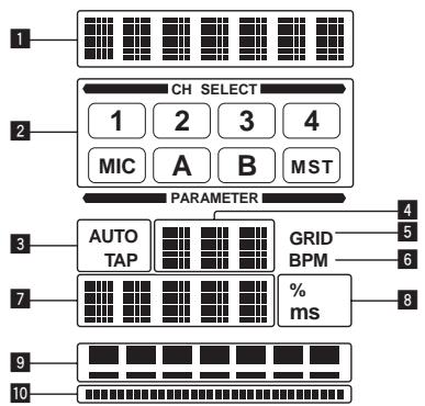
1 BbInonHnTe warr ot 1 do 4 npoeDpypbI BEAT EFFECT.
2 PnPKoCHNTecb K [X-PAD].
[X-PAD] BKJIIOUaET N OTKJIIOUaET 3ΦΦeKT N I3MeHReT KOJIYeCTBeHHbI nI npaMeTp.
1 BbInonHnTe warr ot 1 do 5 npoeDpybI BEAT EFFECT.
2 PnPKoCHNTecb K [X-PAD].
[X-PAD] n3MeHReT KOJIInueCTBeHHbI npaMeTp 3ΦΦeKtA.
UnpaBJIeHne npOrpaMMbIM o6ecpeHHeM DJ c NOMOuI OyHKcN MIDI
Даннbi annapat BbIbOHT INHфорmaциуnpaВленя KHONkamnpykamn ByHBPcAblHomФopMaTe MIDI.
ПдкИОчИВИшьК komпьЮтуру чeze USK ka6eь,Ha KOTOpOM yCTaHOBNeHO COBMeCTnMoE c MIDI nporpamMHOte obecneueHne DJ, nporpamMbIM obecneHHeM DJ moXHo 6ydet YnpabJrTb OT dAnHOro annapata.
3apahee yctaHOBInTe nporpamMHOe o6ceuehene DJ ha kombHOpet. TaKke, oterpyuye aayno i MIDI hactpoiKn dny nporpamMHOo o6ceueheny DJ
- Iopno6Hee o hactpoKe kahana MIDI cmToPte N3meHene hactpoek ha ctp. 23.
- По-coobшеним, Выдаваebмданьим apapatom, CMOTpnte Cnncok coob-шени MIDI haстр. 21.
1 Поdkлочи Термнанл [USB] дан Horo annapata K komlbOTepy.
IoiKIIIOHTe CHOa BHeuHn 3ΦΦeKToP,dp.
![PIONEER DJM-900NXS - Поdkлочи Термнанл [USB] дан Horo annapata K komlbOTepy. - 1](/content/2019/11/118942/images/073a3f6c4fcfcfc14d2b2c5b8ffee97fc04fb5dc0ff50de61a19a32c644f9c38.jpg)
| Кнопп BEAT←, ➔ (napa-metр 1) | — |
| Ручka TIME (napametр 2) | — |
| Ручka LEVEL/DEPTH (napametр 3) | Pergunnye t yrobeь 3вуань, постунець на терminал [RETURN]. |
| X-PAD (napametр 4) | — |
MIDI LFO
Φopma KojébaHni MIDI-cuHaHa (0-127) u3MeHЯETcB B COOTBeTcBn C TeMnOM dopoKKn.
Cxema φορмь кοлбаний MIDI-cuRGHana nepeKlnOuaetc npri KaKdOM hakatn KhoIGN [LFO FORM (WAKE UP)].
Yka3aHHbIe 3dEcB Ha3BaHnI KOMpaHn I N3dJIIn YBJIHOCTc TOPKOBbIMI MapkAMINx COOTBeTCTByIOUx BlaJeBcE.B.
TexHnueckne xapaKTepNCTnKN
HeincpaBHOCTN
Tpe6obAHnK nHTaHIO 220Bdo240B nepeMeHHoro Toka,50T/60T
IopTe6nemam MoHoctb. 41 Bt
Iotppe6nemamouchoctb(BpeKmmeOxuDahna) .0.4BT
Bec ochoBHoro annapata 7.1 K
MaKc.ra6apntbl 331 MM (U) × 107.9 MM (B) × 409 MM (Γ)
Донуckaemma pa6o7a TempepaTpa .OT +5^ do +35^
Донусямая рабочая влajховс.......OT 5%do 85%(6e3 kondeнcaци)
Aynopa3d
JachToa nckpeTn3aun 96 K
OCHOBHOI zuΦpoBO-aHanoRObI npeo6pa3oBaTeIb 32 6nt
Дугге ananorobо-цфровьи ицфробо-ahanorobьп пeoбразел.24 6nt
YactOTHaXapaKTepeNCTnKa
CD/LINE 20 Tdo 20K
CoOTHOSeHHe CNrHaI/7yM (HOMnHaJIbHbIy BbIXoJ)
PHONO 88d
CD/LINE 105
MIC1, MIC2 84
06ee HeiHHeHoe nckaeHne (CD/LINE - MASTER1) 0.005%
CTaHapThbI ypoBeHb BXOa /IMpeHaCb BXOa
PHONO. -52 dBu/47 kΩ
CD/LINE -12 dBu/47 kΩ
MIC1. -52 dBu/8 kΩ
MIC2 -52 dBu/12 kΩ
RETURN -12 dBu/47 kΩ
CTaHapThbI ypOBeHb BixOda /IMneHaHc Harpy3Kn /IMneHaHc BixOda
MASTER1 +8 dBu/10 kΩ/5 Ω nii nixe
MASTER2 +2 dBu/10 kΩ/22 Ωилннжke
REC OUT. -8 dBu/10 kΩ/22 Ω nIIN Hnke
BOOTH. +8dBu / 10k /1k nnnnHnke
SEND -12 dBu/10 kΩ/1 kΩ nui nixke
PHONES. +8,5 dBu/32 /1 Ω nnnn Hnke
HOMHaJIbHbI yPOBeH bIxOa /ImpeHaC harpy3Kn
MASTER1 +26 dBu/10 kΩ
MASTER2 +22 dBu/10 kΩ
IepexoJHoe 3aTyxAHne (LINE) 82 n6
XapakTepcntKn3KbAla3epa KaHana
HI. -26 D5 do +6 D5 (13 KfU)
MID .0T-26 d5 do +6 d5 (1 kT)
LOW .0T-26 d5 do +6 d5 (70 T)
XapakTepcntKnEKBaJaH3epa MmKpOpoHa
HI. -12D+12D(10K
LOW .-12 dBdo+12 dB(100Tc)
TepMNHaJIbI BXOda/BbIXOda
BxOHN TePmHaJ PHONO
UtbipbkoBoe rHe3do RCA 2 h6opa
BxOJHON TePmHaJ CD/LINE
UbpbkoBbIe rHe3da RCA. 4 h6op
BxOJHOTepmHaI LINE
山TbIpbKOBoe rHe3do RCA 2 h6opa
BxOdHOn TePmHaN MIC2
THe3doHayuHnKOB(6,3MM) 1ha6op
BxodHbIe TepMnHaJIbI RETURN
Tne3do HayshnKOB (6,3 MM) 1 ha6op
KoakcnaJIbHbI BxOdHoi TePMHaJ DIGITAL IN
UtbipbKOBbie rHe3da RCA. 4 H6op
BbIXoHoi TePmHaI MASTER
KOHHeKTop XLR 1 ha6op
UtbipbkoBbIe rhe3da RCA. 1 na6op
BbIXoHNo TepMnHaN BOOTH
Гнебу hayшнков (6,3 MM) 1 ha6op
BbIXoHoi TepmHaI REC OUT
UbpbKOBbIe rHe3da RCA. 1 ha6op
BbIXoHNo TePmHaJ SEND
THe3doHayuHnKOB(6,3MM) 1ha6op
KoakcnanbHbBbIXOHOI TepMNHaJ DIGITAL MASTER OUT
UItbIpbKOBbIe rHe3da RCA. 1 ha6op
TepMNHaI MIDI OUT
5P DIN 1 ha6op
BbIXoHNo TepMnHaJI PHONES
Ctepeoohnueckoe rHe3no HayuHnKOB (6,3 MM) 1 ha6op
TepmHaJ USB
Tun B. 1 ha6op
TepMNHaJI LINK
TepmHaI LAN (100Base-TX) 1 h6op
TexHnueckne xapaKTepeNCTKN KONcTpKUIN daHHOrO u3JeINa MOryt n3MeHrTbcSbe3 yBeDoMJIeHN.
- ИztánO Pioneer Corporation. © Pioneer Corporation, 2011. Bce npaba coxpaHeNbI.
Приимechanical:
B COOTBETCTBmN CO CTAbEi 5 3aKoHa PocCnIckOepeaun "O 3aIte npab NotpebTeTЯ" uYka3aHnem IpaBntbCTBa PocCnIckOepeaun No 720 ot 16 nIOy 1997 roDa kOpnpaun Pioneer Europe NV yCTaHaBJIbAeT ycNoBHe Na cIeDyHOuYO npOdoJXtJIbHOcTb cPoka cIyXbI oΦuZaJIbHO noCTaBJIeMbIX Ha PocCnIK pblHOK TObApOB.
Aydno n Bndeoo6bpyoBaHne: 7 let
Ipehenochoe aydnoobopyoBaHne: 6 let
Published by Pioneer Corporation.
Copyright © 2011 Pioneer Corporation.
All rights reserved.
Publication de Pioneer Corporation.
© 2011 Pioneer Corporation.