
DJM-700-S - DJ mixer PIONEER - Free user manual and instructions
Find the device manual for free DJM-700-S PIONEER in PDF.
| Product Type | 4-channel DJ Mixer |
| Brand | Pioneer |
| Model | DJM-700-S |
| Dimensions (W x D x H) | 320 mm x 378.4 mm x 107.9 mm |
| Weight | 6.6 kg |
| Power Supply | 220-240 V, 50/60 Hz, 33 W |
| Sampling Rate | 96 kHz |
| A/D and D/A Converter | 24-bit |
| Frequency Response | LINE: 20 Hz - 20 kHz, PHONO: 20 Hz - 20 kHz (RIAA), MIC: 20 Hz - 20 kHz |
| Signal-to-Noise Ratio | LINE: 104 dB, PHONO: 94 dB, MIC: 82 dB |
| Built-in Effects | Delay, Echo, Trans, Filter, Flanger, Phaser, Reverb, Robot, Crush, Roll, Reverse Roll, Up Roll, Down Roll, Send/Return |
| Manual Filter and Effect Frequency Filter | Yes, with FREQUENCY knob |
| Per-Channel EQ | 3-band (HI, MID, LOW) with range -26 dB to +6 dB |
| Microphone EQ | 2-band (HI, LOW) with range -12 dB to +12 dB |
| Talk Over Function | Yes, 20 dB attenuation of other sources |
| Fader Start | Yes, compatible with Pioneer DJ CD players |
| Inputs | 3 x PHONO (RCA), 2 x CD (RCA), 3 x LINE (RCA), 2 x MIC (XLR and 6.3mm jack), 1 x RETURN (6.3mm jack) |
| Outputs | MASTER 1 (XLR), MASTER 2 (RCA), BOOTH (RCA), REC (RCA), SEND (6.3mm jack), DIGITAL (coaxial RCA), PHONES (stereo 6.3mm jack) |
| MIDI OUT | Yes, 5-pin DIN connector, transmits commands and BPM clock |
| Control Connectors | 2 x 3.5mm mini-jack for Pioneer DJ CD players |
| Fader Curve Selector | CH FADER: 2 types, CROSS FADER: 3 types |
| Operating Temperature | +5°C to +35°C |
| Operating Humidity | 5% to 85% (no condensation) |
| Cleaning | Dry or slightly damp soft cloth with diluted neutral detergent; do not use solvents |
| Included Accessories | Instruction Manual |
Frequently Asked Questions - DJM-700-S PIONEER
User questions about DJM-700-S PIONEER
0 question about this device. Answer the ones you know or ask your own.
Ask a new question about this device
Download the instructions for your DJ mixer in PDF format for free! Find your manual DJM-700-S - PIONEER and take your electronic device back in hand. On this page are published all the documents necessary for the use of your device. DJM-700-S by PIONEER.
USER MANUAL DJM-700-S PIONEER
Operating Instructions
Mode d'emploi
Bedienungsanleitung
Thank you for buying this Pioneer product.
Please read through these operating instructions so you will know how to operate your model properly. After you have finished reading the instructions, put them away in a safe place for future reference.
In some countries or regions, the shape of the power plug and power outlet may sometimes differ from that shown in the explanatory drawings. However the method of connecting and operating the unit is the same.
IMPORTANT

The lightning flash with arrowhead symbol, within an equilateral triangle, is intended to alert the user to the presence of uninsulated "dangerous voltage" within the product's enclosure that may be of sufficient magnitude to constitute a risk of electric shock to persons.
CAUTION
RISK OF ELECTRIC SHOCK DO NOT OPEN
CAUTION:
TO PREVENT THE RISK OF ELECTRIC SHOCK,DO NOT REMOVE COVER (OR BACK).NO USER SERVICEABLE PARTS INSIDE.REFER SERVICING TO QUALIFIED SERVICE PERSONNEL.

The exclamation point within an equilateral triangle is intended to alert the user to the presence of important operating and maintenance (servicing) instructions in the literature accompanying the appliance.
D3-4-2-1_En-A
Replacement and mounting of an AC plug on the power supply cord of this unit should be performed only by qualified service personnel.
IMPORTANT: THE MOULDED PLUG
This appliance is supplied with a moulded three pin mains plug for your safety and convenience. A 5 amp fuse is fitted in this plug. Should the fuse need to be replaced, please ensure that the replacement fuse has a rating of 5 amps and that it is approved by ASTA or BSI to BS1362.
Check for the ASTA mark or the BSI mark on the body of the fuse.
If the plug contains a removable fuse cover, you must ensure that it is refitted when the fuse is replaced. If you lose the fuse cover the plug must not be used until a replacement cover is obtained. A replacement fuse cover can be obtained from your local dealer.
If the fitted moulded plug is unsuitable for your socket outlet, then the fuse shall be removed and the plug cut off and disposed of safely. There is a danger of severe electrical shock if the cut off plug is inserted into any 13 amp socket.
If a new plug is to be fitted, please observe the wiring code as shown below. If in any doubt, please consult a qualified electrician.
IMPORTANT: The wires in this mains lead are coloured in accordance with the following code:
Blue: Neutral Brown:Live
As the colours of the wires in the mains lead of this appliance may not correspond with the coloured markings identifying the terminals in your plug, proceed as follows ;
The wire which is coloured BLUE must be connected to the terminal which is marked with the letter N or coloured BLACK.
The wire which is coloured BROWN must be connected to the terminal which is marked with the letter L or coloured RED.
How to replace the fuse: Open the fuse compartment with a screwdriver and replace the fuse.
D3-4-2-1-2-2_B_En
Operating Environment
Operating environment temperature and humidity: +5^ + + 35^(+41^ + + 95^) less than 85% RH (cooling vents not blocked)
Do not install this unit in a poorly ventilated area, or in locations exposed to high humidity or direct sunlight (or strong artificial light) D3-4-2-1-7c_A_En
WARNING
To prevent a fire hazard, do not place any naked flame sources (such as a lighted candle) on the equipment. D3-4-2-1-7a
D3-4-2-1-7a A En
WARNING
Before plugging in for the first time, read the following section carefully.
The voltage of the available power supply differs according to country or region. Be sure that the power supply voltage of the area where this unit will be used meets the required voltage (e.g., 230V or 120V) written on the bottom panel. D3-4-2-1-4_A.En mod
If the AC plug of this unit does not match the AC outlet you want to use, the plug must be removed and appropriate one fitted. Replacement and mounting of an AC plug on the power supply cord of this unit should be performed only by qualified service personnel. If connected to an AC outlet, the cut-off plug can cause severe electrical shock. Make sure it is properly disposed of after removal. The equipment should be disconnected by removing the mains plug from the wall socket when left unused for a long period of time (for example, when on vacation). D3-4-2-1a_A_En
CAUTION
The POWER switch on this unit will not completely shut off all power from the AC outlet. Since the power cord serves as the main disconnect device for the unit, you will need to unplug it from the AC outlet to shut down all power. Therefore, make sure the unit has been installed so that the power cord can be easily unplugged from the AC outlet in case of an accident. To avoid fire hazard, the power cord should also be unplugged from the AC outlet when left unused for a long period of time (for example, when on vacation). D3-4-2-2a_A_En
WARNING
This equipment is not waterproof. To prevent a fire or shock hazard, do not place any container filed with liquid near this equipment (such as a vase or flower pot) or expose it to dripping, splashing, rain or moisture. D3-4-2-1-3_A.En
VENTILATION CAUTION
When installing this unit, make sure to leave space around the unit for ventilation to improve heat radiation (at least 5 cm at rear, and 3 cm at each side).
WARNING
Slots and openings in the cabinet are provided for ventilation to ensure reliable operation of the product, and to protect it from overheating. To prevent fire hazard, the openings should never be blocked or covered with items (such as newspapers, table-cloths, curtains) or by operating the equipment on thick carpet or a bed. D3-4-2-1-7b_A.En
This product complies with the Low Voltage Directive 2006/95/EC and EMC Directive 2004/108/EC.
D3-4-2-1-9a_A_E_n

If you want to dispose this product, do not mix it with general household waste. There is a separate collection system for used electronic products in accordance with legislation that requires proper treatment, recovery and recycling.
Private households in the member states of the EU, in Switzerland and Norway may return their used electronic products free of charge to designated collection facilities or to a retailer (if you purchase a similar new one).
For countries not mentioned above, please contact your local authorities for the correct method of disposal.
By doing so you will ensure that your disposed product undergoes the necessary treatment, recovery and recycling and thus prevent potential negative effects on the environment and human health. K058.A
When using this product follow the instructions written on the underside of the unit, which concern rated voltage, etc. D3-4-2-2-4_En
K058_A_En
POWER-CORD CAUTION
Handle the power cord by the plug. Do not pull out the plug by tugging the cord and never touch the power cord when your hands are wet as this could cause a short circuit or electric shock. Do not place the unit, a piece of furniture, etc., on the power cord, or pinch the cord. Never make a knot in the cord or tie it with other cords. The power cords should be routed such that they are not likely to be stepped on. A damaged power cord can cause a fire or give you an electrical shock. Check the power cord once in a while. When you find it damaged, ask your nearest PIONEER authorized service center or your dealer for a replacement. S002_En
Contents
CONFIRM ACCESSORIES 4
CAUTIONS REGARDING HANDLING. 4
Location 4
Cleaning the Unit 4
FEATURES 4
CONNECTIONS 5
CONNECTION PANEL 5
CONNECTING INPUTS 6
CONNECTING EXTERNAL EFFECTORS, OUTPUT
CONNECTORS 7
ABOUT MIDI CONNECTORS 8
CONNECTING MICROPHONE AND HEADPHONES 8
CONNECTING THE POWER CORD 8
NAMES AND FUNCTIONS OF PARTS 9
MIXER OPERATIONS 13
FADER START FUNCTION 14
EFFECT FUNCTIONS 16
PRODUCING BEAT EFFECTS 18
Operating Instructions. 1
CAUTIONS REGARDING HANDLING
Location
Install the unit in a well-ventilated location where it will not be exposed to high temperatures or humidity.
- Do not install the unit in a location which is exposed to direct rays of the sun, or near stoves or radiators. Excessive heat can adversely affect the cabinet and internal components. Installation of the unit in a damp or dusty environment may also result in a malfunction or accident. (Avoid installation near cookers etc., where the unit may be exposed to oily smoke, steam or heat.)
- When the unit is used inside a carrying case or DJ booth, separate it from the walls or other equipment to improve heat radiation.
Cleaning the Unit
- Use a polishing cloth to wipe off dust and dirt.
- When the surfaces are very dirty, wipe with a soft cloth dipped in some neutral cleanser diluted five or six times with water and wrung out well, then wipe again with a dry cloth. Do not use furniture wax or cleaners.
- Never use thinners, benzene, insecticide sprays or other chemicals on or near this unit, since these will corrode the surfaces.
FEATURES
Designed for high sound quality
Analog signals are transmitted by the shortest circuitry and converted to digital format at 96 kHz sampling rate via a 24-bit high quality A/D converter. As a result, signals are passed to the digital mixing stage in the best possible state. Mixing is performed with a 32-bit DSP, totally eliminating any loss in fidelity, while the ideal level of filtering is introduced to produce optimum sound for DJ play.
These features are housed in a high-rigidity chassis with high-output power section and other features that carry on the high-fidelity performance of the DJM-1000, thus ensuring the utmost in clear and powerful club sound.
Manual Filter
This unit features Manual Effector for more intuitive setting of effects, thus expanding the potential range of DJ play. In addition, by combining this with "beat effects," an even wider range of effects can be produced, allowing a tremendous variety of remix and DJ play.
Beat effects
The "beat effects" so popular on the DJM-600 are continued here. Effects can be applied in linkage to the BPM (Beats Per Minute) count, thus allowing the production of a variety of sounds. Equipped with a broad range of special effects, including delay, echo, trans, filter, flanger, phaser, reverb, robot, crush, roll, reverse roll, uproll, and downroll.
This unit features an "effect frequency filter" allowing the user to limit what frequency bands are subjected to effects, and which are not. This enhances the degree of audio expression compared to conventional effecters that are applied to the entire frequency range.
Digital OUT
The digital output connectors support sampling rates 96 kHz/24-bit format and 48 kHz/24-bit format, making the unit even more convenient for cutting studio tracks or on other occasions when high sound fidelity is required. (Only linear PCM is supported.)
MIDI OUT
Virtually all the dial and switch information of the DJM-700-S/ DJM-700-K can be output in MIDI signal format, allowing a component supporting MIDI control to be controlled via MIDI.
Other functions
- A control cable can be used to connect the unit to a Pioneer DJ CD player, thus allowing playback to be linked to operation of the fader ("fader start play").
- Built-in "3-band equalizer" supports level control within the range of +6 dB to -26 dB in each bandwidth.
- "Cross fader assignment" function allows each channel's input to be assigned flexibly to a cross fader.
- "Talk over" function automatically lowers track volume during microphone input.
- "Fader curve adjustment" function allows modification of the cross fader and channel fader curves.
CONNECTIONS
CONNECTION PANEL
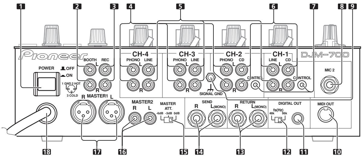
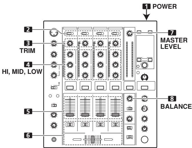
1 POWER switch
2 BOOTH monitor output connectors
RCA-type booth monitor output jack.
The sound level from these connectors is controlled independently by the BOOTH MONITOR LEVEL dial, regardless of the position of the MASTER LEVEL dial.
3 Recording output connectors (REC)
RCA type output connectors for recording.
4 PHONO input connectors
RCA type phono level (MM cartridge) input connectors. Do not use for inputting line level signals.
5 LINE input connectors
RCA type line level input connectors.
Use to connect a cassette deck or other line level output component.
6 CD input connectors
RCA type line level input connectors.
Use to connect a DJ CD player or other line level output component.
7 CONTROL connectors
Ø3.5 mm mini-connector. Use to connect to the control connector of a Pioneer DJ CD player.
When the connectors are connected, the DJM-700-S/DJM-700-K's fader can be used to perform start/stop on the DJ CD player.
8 Two microphone input jacks (MIC 2)
Connect microphones equipped with phone-type plugs.
9 Signal grounding terminals (SIGNAL GND)
Reduces noise when connecting an analog turntable.
10 MIDI OUT connector
DIN type output connector.
Use to connect to other MIDI component (see P. 21).
11 DIGITAL OUT connector
RCA type digital coaxial output connector.
Master audio digital output.
12 Sampling frequency selector switch (fs 48 k/96 k)
Use to set the sampling frequency of the digital output to 96 kHz/24-bit format or 48 kHz/24-bit format.
- Turn power off before changing this switch position.
13 RETURN connectors
6.3 mm phone-type input connectors.
Use to connect to the output connectors of external effectors or similar components.
When the L channel only is connected, the L channel input is simultaneously input to the R channel.
14 SEND output connectors
6.3 ~mm phone-type output connectors.
Use to connect to the input connectors of external effectors or other similar components. When the L channel only is connected, a L+R monaural signal is output.
15 Master output attenuator switch (MASTER ATT)
Use to attenuate the level of the master 1 and master 2 outputs. Attenuation can be set to 0 dB, -3 dB, or -6 dB.
16 MASTER 2 output connectors
RCA type unbalanced output.
17 MASTER 1 output connectors
XLR type (male) balanced output.
- When using a cord with RCA-type plug, users are recommended to connect the plug directly to the MASTER 2 connectors without using an XLR/RCA converter plug.
18 Power cord
Connect to ordinary AC outlet.
Always turn off the power switch and disconnect the power plug from its outlet when making or changing connections.
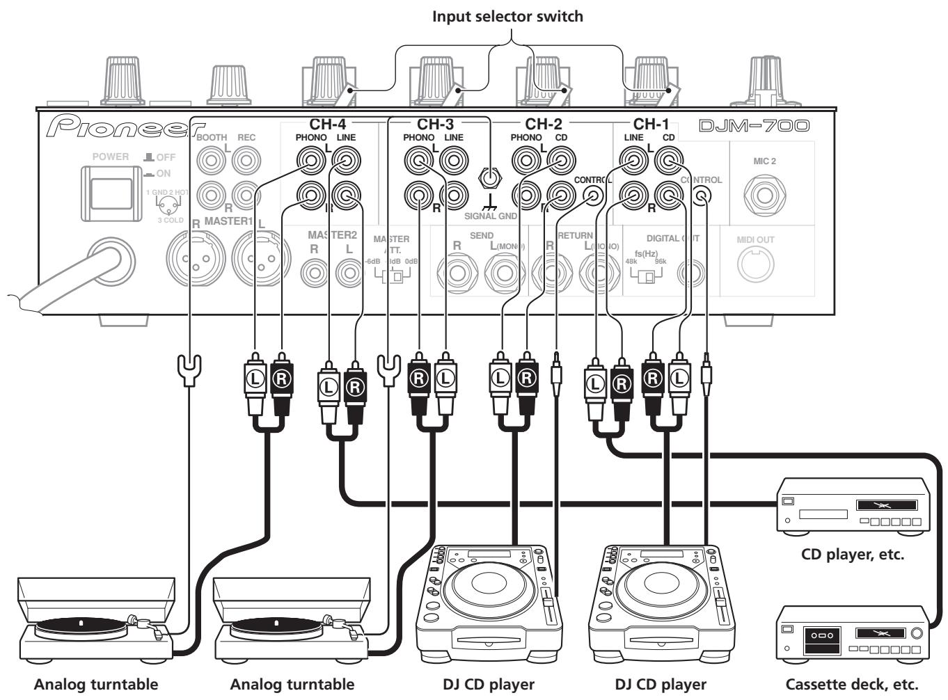
CONNECTING INPUTS
Pioneer DJ CD players
The audio output connectors of a DJ-type CD player can be connected to the CD input connectors (channel 1 or 2), or to the LINE input connectors (channel 1) of the DJM-700-S/DJM-700-K. Connect the control cord to the CONTROL jack, and set the input selector switch to [CD] or [LINE].
Analog turntable
To connect an analog turntable, connect the turntable's audio output cable to one of the channel 2 to 4 PHONO input connectors. Set the corresponding channel's input selector switch to [PHONO]. The DJM-700-S/DJM-700-K's PHONO inputs support MM cartridges.
Connect the ground wire from an analog turntable to the SIGNAL GND terminal of the DJM-700-S/DJM-700-K.
Note that no PHONO input connector is provided for channel 1.
Connecting other line level output devices
To use a cassette deck or ordinary CD player, connect its audio output connectors to one of the DJM-700-S/DJM-700-K's LINE input connectors (channel 1, 3, or 4) or to the CD input connectors (channel 1 or 2), and set the input selector switch to [LINE].
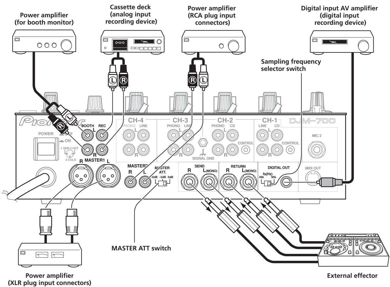
CONNECTING EXTERNAL EFFECTORS, OUTPUT CONNECTORS
Master output
This unit is furnished with balanced output MASTER 1 (supporting XLR plugs), and unbalanced output MASTER 2 (supporting RCA plugs).
Using the MASTER ATT switch, adjust the output level to match the input sensitivity of the power amplifier used.
If the operating panel's MONO/STEREO switch is set to [MONO], the master output will be a monaural combination of L+R channels.
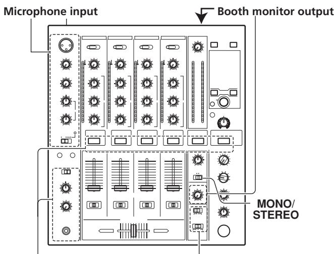
Booth monitor output
Unbalanced output supporting RCA-type plug. The sound volume for this output is controlled by the BOOTH MONITOR LEVEL dial, independently of the master output level setting.
Recording output
These are output connectors for recording, supporting RCA plugs.
Digital output
This is a coaxial digital output connector, supporting RCA plugs. The sampling frequency can be set to 96 kHz/24-bit format or 48 kHz/24-bit format to match the connected device.
- Turn power off before changing this switch position.
External effector
Use a cable with 06.3 mm phone plugs to connect the DJ mixer's SEND connectors to the effector's input connectors.
When using an effector with monaural inputs, connect only to the DJ mixer's L channel output. In this way, the mixed L + R audio signal will be sent to the effector. In the same way, use a cable with 06.3 mm phone plugs to connect the DJ mixer's RETURN
connectors to the output connectors of the effector. If the effector has only monaural output, connect to the DJ mixer's L channel input only. The signal from the effector will be input to both L and R channels.
When using an external effector, set the effect selector to [SND/ RTN].
ABOUT MIDI CONNECTORS
See P. 21 regarding the functions of MIDI connectors.
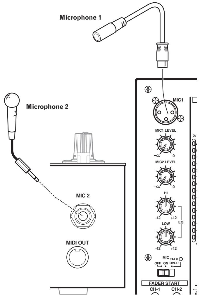
CONNECTING MICROPHONE AND HEADPHONES
Microphone
A microphone with XLR-type plug can be connected to the MIC 1 connector on the Operation Panel (upper).
The MIC 2 jack on the connection panel can be used to connect a microphone with 06.3mm phone plugs.
- When using a microphone, set the operating panel's MIC switch to [ON] or [TALK OVER], and adjust the LEVEL dial as necessary.
When not using a microphone, it is recommended to set the
MIC switch to [OFF] and rotate the LEVEL dial fully counterclockwise to the [- ] side.
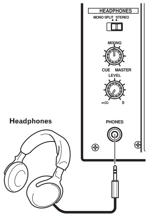
Headphones
The PHONES jack on the upper surface of the operating panel can be used to connect headphones with a 06.3 mm stereo phone plug.
Connect the power cord last.
- After completing all other connections, connect the power plug to an ordinary AC outlet.
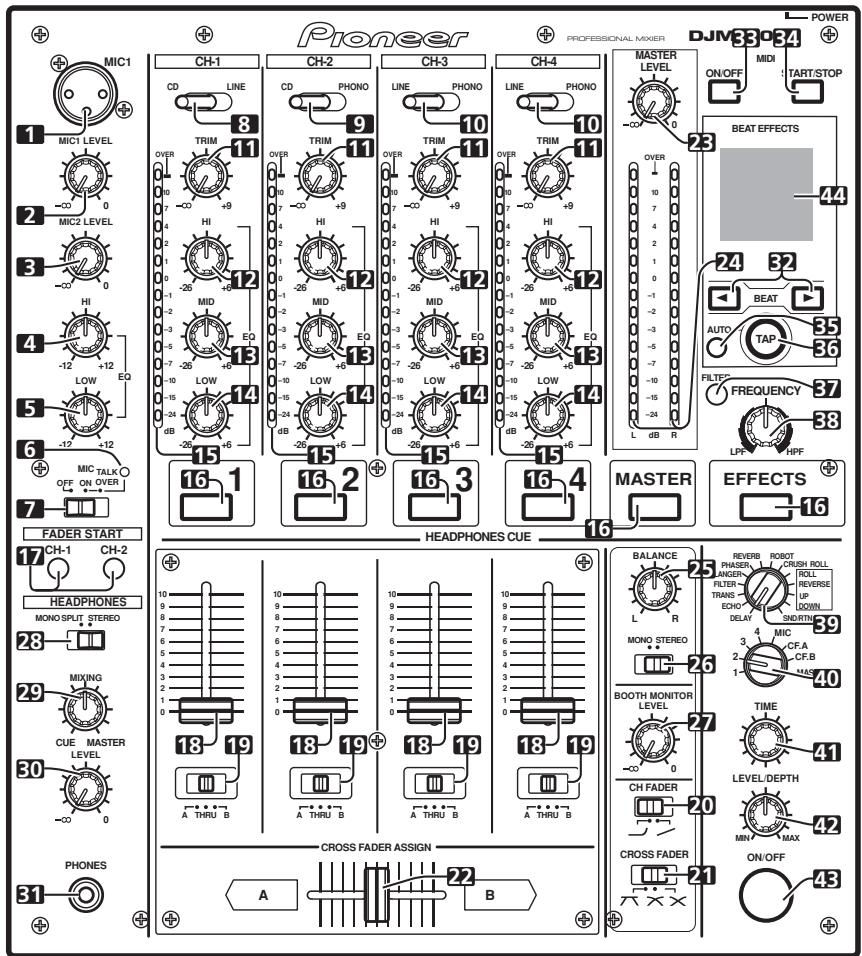
NAMES AND FUNCTIONS OF PARTS
OPERATION PANEL

1 Microphone 1 input jack (MIC 1)
Connect microphone with XLR-type plug.
2 Microphone 1 level control dial (MIC 1 LEVEL)
Use to adjust the volume of microphone 1. (adjustable range - to 0 dB)
3 Microphone 2 level control dial (MIC 2 LEVEL)
Use to adjust the volume of microphone 2. (adjustable range - to 0 ~dB )
4 Microphone equalizer high-range control dial (HI)
Use to adjust the treble (high-range) frequencies of microphones 1 and 2. (adjustable range -12 dB to +12 dB)
5 Microphone equalizer low-range control dial (LOW)
Use to adjust the bass (low-range) frequencies of microphones 1 and 2. (adjustable range -12 dB to +12 dB)
6 Microphone function indicator
Lights when microphone is ON; flashes when TALK OVER is ON.
7 Microphone function selector switch (MIC)
OFF:
No microphone sound is output.
ON:
Microphone sound is output normally.
TALK OVER:
Microphone sound is output; when sound is input to a connected microphone, the TALK OVER function operates and all sound other than that from the microphone is attenuated by 20 dB.
- When not using the TALK OVER function, it is recommended to set the switch to the [OFF] or [ON] position.
8 Channel 1 input selector switch
CD:
Selects CD input (line level analog input).
LINE:
Use to select LINE input connectors.
9 Channel 2 input selector switch
CD:
Selects CD input (line level analog input).
PHONO:
Use to select PHONO input connectors (analog turntable input).
10 Channel 3, 4 input selector switch
LINE:
Selects LINE input (line level analog input).
PHONO:
Use to select PHONO input connectors (analog turntable input).
11 TRIM adjust dial
Use to adjust the input level for each channel. (adjustable range: - to +9 dB, mid-position is about 0 dB)
12 Channel equalizer high-range adjust dial (HI)
Use to adjust the treble (high-range) frequency sound for each channel. (adjustable range: -26 dB to +6 dB)
13 Channel equalizer mid-range adjust dial (MID)
Use to adjust the mid-range frequency sound for each channel. (adjustable range: -26 dB to +6 dB)
14 Channel equalizer low-range adjust dial (LOW)
Use to adjust the bass (low-range) frequency sound for each channel. (adjustable range: -26 dB to +6 dB)
15 Channel level indicator
Displays the current level for each channel, with two-second peak hold.
16 HEADPHONES CUE buttons/indicators
These buttons are used to select from 1 to 4, MASTER, or EFFECTS, to allow you to monitor the desired source through headphones. If multiple buttons are pressed simultaneously, the selected audio sources are mixed. Press the button once more to cancel the selected source. Unselected buttons glow darkly, while selected source buttons light brightly.
17 Fader start button/indicator (FADER START CH-1, CH-2)
Enables the fader start/back cue function for the channel to which a DJ CD player is connected. The button lights when set to ON. When enabled, the operation differs depending on the setting of the CROSS FADER ASSIGN switch.
- When the CROSS FADER ASSIGN switch is set to the [A] or [B] position, fader start button operation is linked to the operation of the cross fader (and unlinked to channel fader).
- When the CROSS FADER ASSIGN switch is set to the [THRU] position, fader start button operation is linked to the operation of the channel fader (and unlinked to cross fader).
18 Channel fader lever
Use to adjust sound volumes for each channel. (adjustable range: - to 0 dB)
Output is in accordance with the channel fader curve selected with the CH FADER curve switch.
19 CROSS FADER ASSIGN switch
This switch assigns each channel's output to either right or left side of the cross fader (if multiple channels are assigned to the same side, the result will be the combined sum of the channels).
A:
The selected channel is assigned to the cross fader's A (left) side.
THRU:
The channel fader's output is sent as is to the master output, without being passed through the cross fader.
B:
The selected channel is assigned to the cross fader's B (right) side.
20 Channel fader curve switch (CH FADER)
This switch allows the user to select from two types of channel fader curve response. This setting is applied equally to channels 1 to 4.
- At the left setting, the curve operates to produce a rapid rise as the channel fader approaches its distant position.
- At the right setting, the curve operates to produce an even, neutral rise throughout the channel fader's movement.
21 Cross fader curve switch (CROSS FADER)
This switch allows the user to select from three types of cross fader curve response.
- At the left setting, the curve produces a rapid signal rise. (As soon as the cross fader lever leaves the [A] side, the [B] channel sound is produced.)
- At the right setting, the curve operates to produce an even, neutral rise throughout the cross fader's movement.
- At the middle setting, an intermediate curve is produced, midway between the two curves noted above.
22 Cross fader lever
Outputs sound assigned to [A] and [B] sides in accordance with setting of the CROSS FADER ASSIGN switch, and subject to the cross fader curve selected with the CROSS FADER curve switch.
23 Master output level dial (MASTER LEVEL)
Use to adjust the master output level. (adjustable range: - to 0 dB)
The master output is the sum combination of the sound from channels set to [THRU] with the CROSS FADER ASSIGN switch; the signal passed through the cross fader; and the signals from microphone 1 and microphone 2 (if the effect selector is set to [SND/RTN], the RETURN input is also added).
24 Master level indicator (MASTER L, R)
These segment indicators display the output level from L and R channels. The indicators have a two-second peak hold.
25 Master balance dial (BALANCE)
Use to adjust the L/R channel balance for master output, booth monitor output, recording output, and digital output.
26 Master output MONO/STEREO selector switch
When set to the [MONO] position, master output, booth monitor output, recording output, digital output are all produced in L+R monaural.
27 BOOTH MONITOR LEVEL control dial
This dial is used to adjust the booth monitor output volume. The volume can be adjusted independently of the master output level. (adjustable range: - to 0dB
28 Headphones output switch (MONO SPLIT/STEREO)
MONOSPLIT:
When HEADPHONES CUE (1, 2, 3, 4 or EFFECTS) button is selected, the selected audio is output to the L channel. When HEADPHONES CUE (MASTER) button is selected, the master audio is output from the R channel.
STEREO:
The audio source selected with the HEADPHONES CUE button is output in stereo.
29 Headphones mixing dial (MIXING)
When rotated clockwise (toward [MASTER]), the master output audio is produced at the headphones (only when [MASTER] has been selected with the HEADPHONES CUE button); when rotated counterclockwise (toward [CUE]), the headphones output becomes the mixture of the effect monitor and the channel selected with the HEADPHONES CUE button.
In the middle position, the audio from [MASTER] and [CUE] will be output.
30 Headphones level adjust dial (LEVEL)
Adjusts the output level of the headphones jack. (adjustable range: - to 0 dB)
31 Headphones jack (PHONES)
Connect to headphones equipped with phone-type jack.
32 Beat select buttons (BEAT)
(Beat up):Doubles the calculated BPM.
(Beat down): Halves the calculated BPM.
(P.18)
- Some effects can be set for "3/4".
With some effects, these are used for functions other than setting the beat.
33 MIDI ON/OFF button
Sets MIDI output function (not including timing lock) to ON/OFF. When power is first turned ON, automatically defaults to OFF.
34 MIDI start/stop button (MIDI START/STOP)
Outputs START/STOP signal for MIDI control function (see P. 21). When this control is enabled, the [MIDI START (STOP)] message appears for two seconds on the display.
MIDI SNAP SHOT:
When the MIDI START/STOP button is held depressed, a snapshot is sent to the external MIDI component.
35 BPM measuring mode button (AUTO)
Switches between the BPM measuring modes AUTO and TAP.
When [AUTO] indicator on the display is lighted, the BPM will be measured automatically.
36 TAP button
The BPM is calculated from the intervals at which the TAP button is struck. If the TAP button is pressed in the AUTO mode, the mode automatically switches to the TAP mode (manual input).
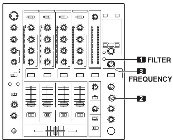
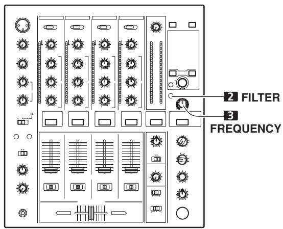
37 MANUAL/EFFECT Frequency filter button
Use to switch between manual filter and effect frequency filter.
When power is first turned ON, defaults to effect frequency filter and the button indicator lights. When manual filter is selected, the button indicator does not light.
38 Manual filter adjust dial (FREQUENCY)
Use to adjust the cutoff frequency of the selected filter.
39 Effect selector (DELAY, ECHO, TRANS, FILTER, FLANGER, PHASER, REVERB, ROBOT (ROBOT VOCODER), CRUSH, ROLL, REVERSE (REVERSE ROLL), UP (UP ROLL), DOWN (DOWN ROLL), SND/RTN (SEND/RETURN))
Use to select desired type of effect (P. 16).
When using an external effector connected to the SEND and
RETURN connectors, set to the [SND/RTN] position
40 Effect channel selector (1, 2, 3, 4, MIC, CF.A, CF.B, MASTER)
Use to select the channel to which effects are applied (P. 18).
When [MIC] is selected, effects are applied to both microphone 1 and microphone 2.
41 Effect parameter 1 dial [TIME (PARAMETER 1)]
Adjusts time parameter for selected effect (P. 18, 20) (With some effects, this is used for adjustments other than time parameters.)
- If the TIME dial is rotated while depressing the TAP button, direct BPM can be set manually.
- If the TIME dial is rotated while holding the TAP button and AUTO/TAP buttons depressed, the BPM can be set in 0.1 units
42 Effect parameter 2 dial [LEVEL/DEPTH (PARAMETER 2)]
Adjusts quantitative parameters for selected effect (P. 18, 20).
43 Effect button/indicator (ON/OFF)
Sets selected effect ON/OFF (P. 18). When power is first turned ON, defaults to effect OFF. When set to effect OFF, the button indicator lights. When effects are enabled (ON), the button flashes.
44 Display
See the following section for details.
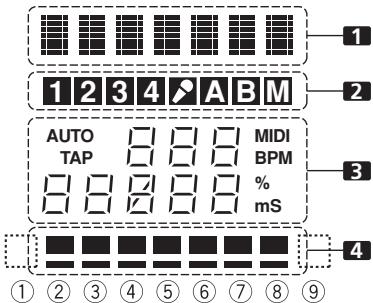
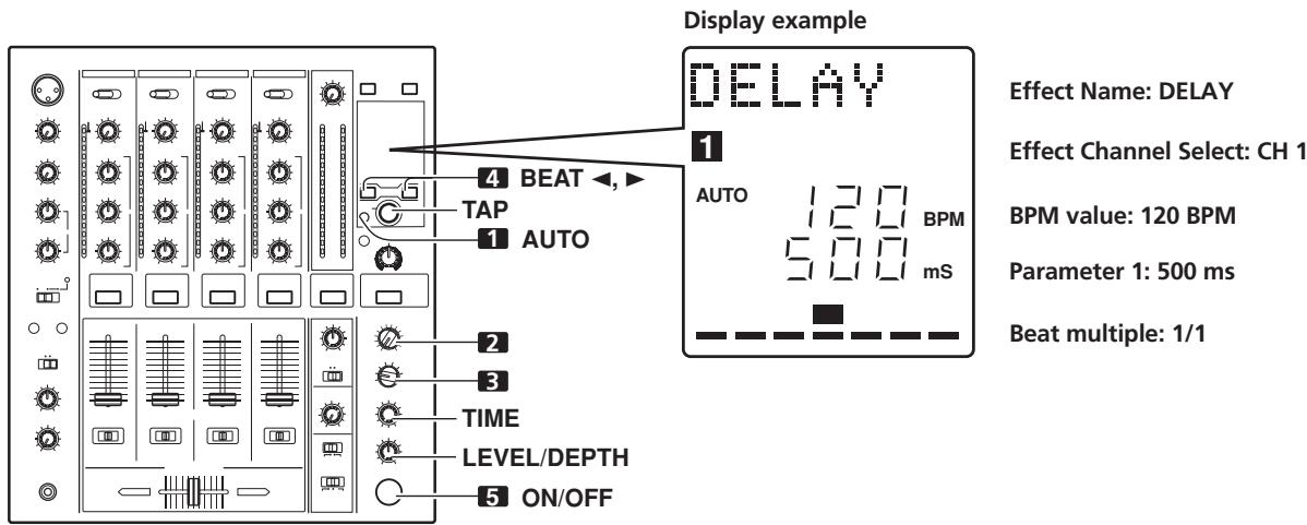
DISPLAY SECTION
1 Effects display section
Text display (7 characters) displays effect name as shown in accompanying table. Also, when one of the change operations is performed as noted in the table, the corresponding characters are displayed for two seconds, after which the display returns to the original effect name.
| Switching Operation | Display |
| At MIDI start | START |
| At MIDI stop | STOP |
| MIDI snapshot | SNAP |
| When MIDI output function is ON | MIDI On |
| When MIDI output function is OFF | MIDIOff |
2 Channel select display section
Lights position selected by effect channel selector.
3 Parameter display section
AUTO/TAP:
[AUTO] lights when the BPM measuring mode is set to AUTO, and [TAP] lights when the BPM measuring mode is set to manual (TAP).
BPM counter display (3 digits):
In AUTO mode, displays the automatically detected BPM value. If the BPM count cannot be detected automatically, the display will flash at the previously detected value. In manual (TAP) mode, displays the BPM value designated by TAP input, etc.
BPM:
Lights constantly.
MIDI:
Indicates status of MIDI output function ON/OFF.
- Lights when MIDI output function is ON.
- Not lighted when MIDI output function is OFF.
Parameter 1 display (5 digits):
Displays parameters designated for each effect. When the beat select buttons (BEAT , ) are pressed, the corresponding beat multiple change is displayed for two seconds. If the beat select buttons (BEAT , ) are used to designate a value outside the parameter range, the current number will flash but will not change.
Unit Display (%/ms):
Lights in accordance with the unit used for each effect.
4 Beat display section
Displays the location of parameter 1 relative to BPM (1/1 beat). The lower row is lighted constantly. When the parameter 1 location approaches a threshold value, the corresponding indicator is lighted. When the parameter 1 is between threshold values, the
indicator flashes. Although the display includes seven actual indicators, the values of the two ends can also be considered to represent indicators, with the result that nine positions can be logically assumed. When the values are at the two ends, no indicators light.
| Effect selector | 1 Effect display | 3 Parameter display | 4 Beat display | |||||||||||
| Effect name | Minimum value | Maximum value | Default | Unit | ① | ② | ③ | ④ | ⑤ | ⑥ | ⑦ | ⑧ | ⑨ | |
| DELAY | DELAY | 1 | 4 000 | 500 | ms | 1/8 | 1/4 | 1/2 | 3/4 | 1/1 | 2/1 | 4/1 | 8/1 | 16/1 |
| ECHO | ECHO | 1 | 4 000 | 500 | ms | 1/8 | 1/4 | 1/2 | 3/4 | 1/1 | 2/1 | 4/1 | 8/1 | 16/1 |
| TRANS | TRANS | 10 | 16 000 | 500 | ms | 1/16 | 1/8 | 1/4 | 1/2 | 1/1 | 2/1 | 4/1 | 8/1 | 16/1 |
| FILTER | FILTER | 10 | 32 000 | 2 000 | ms | 1/4 | 1/2 | 1/1 | 2/1 | 4/1 | 8/1 | 16/1 | 32/1 | 64/1 |
| FLANGER | FLANGER | 10 | 32 000 | 2 000 | ms | 1/4 | 1/2 | 1/1 | 2/1 | 4/1 | 8/1 | 16/1 | 32/1 | 64/1 |
| PHASER | PHASER | 10 | 32 000 | 2 000 | ms | 1/4 | 1/2 | 1/1 | 2/1 | 4/1 | 8/1 | 16/1 | 32/1 | 64/1 |
| REVERB | REVERB | 1 | 100 | 50 | % | 10 | 20 | 30 | 40 | 50 | 60 | 70 | 80 | 90 |
| ROBOT | ROBOT | -100 | 100 | 0 | % | — | -100 | -66 | -50 | 0 | 26 | 50 | 100 | — |
| CRUSH | CRUSH | 10 | 32 000 | 2 000 | ms | 1/4 | 1/2 | 1/1 | 2/1 | 4/1 | 8/1 | 16/1 | 32/1 | 64/1 |
| ROLL | ROLL | 10 | 4 000 | 500 | ms | 1/16 | 1/8 | 1/4 | 1/2 | 1/1 | 2/1 | 4/1 | 8/1 | 16/1 |
| REV ROLL | REVROLL | 10 | 4 000 | 500 | ms | 1/16 | 1/8 | 1/4 | 1/2 | 1/1 | 2/1 | 4/1 | 8/1 | 16/1 |
| UP ROLL | UP ROLL | 10 | 4 000 | 500 | ms | 1/16 | 1/8 | 1/4 | 1/2 | 1/1 | 2/1 | 4/1 | 8/1 | 16/1 |
| DOWN ROLL | DOWNROLL | 10 | 4 000 | 500 | ms | 1/16 | 1/8 | 1/4 | 1/2 | 1/1 | 2/1 | 4/1 | 8/1 | 16/1 |
| SND/RTN | SND/RTN | |||||||||||||
Shaded items are not displayed.
MIXER OPERATIONS
BASIC OPERATIONS
1 Set rear panel POWER switch to ON.
2 Set the input selector switch for the desired channel to choose the connected component.
- CH1: Set to [CD] or [LINE]
CH2: Set to [CD] or [PHONO].
CH3/4: Set to [LINE] or [PHONO].
3 Use the TRIM dial to adjust the input level.
4 Use the channel equalizer dials (HI, MID, LOW) to adjust the tone.
5 Use the channel fader lever to adjust the sound volume of the selected channel.
6 To use the cross fader on the selected channel, set the CROSS FADER ASSIGN switch to either cross fader channel A or channel B, and operate the cross fader lever.
- When not using the cross fader, set the CROSS FADER ASSIGN switch to [THRU].
7 Use the MASTER LEVEL dial to adjust the overall sound volume.
8 Use the BALANCE dial to adjust the sound balance between right and left.
Headphones output
Fader curve
[Selecting Stereo or Monaural]
When the MONO/STEREO switch is set to [MONO], the master output becomes a monaural combination of L + R channels.
[Microphone Input]
1 To use a microphone, set the MIC switch to [ON] or [TALK OVER].
- When the switch is set to [TALK OVER], any time a sound of over -15 dB is detected by the microphone, the output for all sound sources other than the microphone are attenuated by 20 dB.
2 Use the MIC 1 LEVEL dial to adjust the sound volume of MIC 1, and use the MIC 2 LEVEL dial to adjust the sound volume of MIC 2.
3 Use the microphone equalizer dials (HI, LOW) to adjust the tone of the microphone sound.
- The microphone equalizer function operates simultaneously on microphone 1 and 2.
[Booth Monitor Output]
1 Use the BOOTH MONITOR LEVEL dial to adjust the sound volume.
- The BOOTH MONITOR LEVEL dial can be used to adjust the sound volume independently of the MASTER LEVEL dial.
[Headphones Output]
1 Use the HEADPHONES CUE buttons (channels 1 to 4, MASTER, EFFECTS) to select the source.
- The selected HEADPHONES CUE button lights brightly.
2 Set the headphones (MONO SPLIT/STEREO) switch.
- When HEADPHONES CUE (1, 2, 3, 4 or EFFECTS) button is selected, the selected audio is output to the L channel. When HEADPHONES CUE (MASTER) button is selected, the master audio is output from the R channel.
- When set to the [STEREO] position, the sound corresponding to the selected HEADPHONES CUE button is output in stereo.
3 When [MONO SPLIT] is selected, use the MIXING dial to adjust the balance of sound between the left channel (sound selected with the HEADPHONES CUE button), and the right channel (the master sound - but only when the HEADPHONES CUE button for the [MASTER] is ON).
- When the MIXING dial is rotated clockwise (toward [MASTER]), the master output (only when the
HEADPHONES CUE button for the [MASTER] is ON) increases; when rotated counterclockwise (toward [CUE]), the sound selected with the HEADPHONES CUE button is output.
4 Use the LEVEL dial to adjust the headphones' sound volume.
[Fader Curve Selection]
Select sound-volume curve corresponding to fader operation.
Use the CH FADER switch to select the desired channel fader response curve.
- At the left setting, the curve operates to produce a rapid rise as the channel fader approaches its distant position.
- At the right setting, the curve operates to produce an even, neutral rise throughout the channel fader's movement.
- This setting applies equally to channels 1 to 4.
Use the CROSS FADER curve switch to select the cross fader curve response.
- At the left setting, the curve produces a rapid signal rise. (As soon as the cross fader lever leaves the [A] side, the [B] channel sound is produced.)
- At the right setting, the curve operates to produce an even, neutral rise throughout the cross fader's movement.
- At the middle setting, an intermediate curve is produced, midway between the two curves noted above.
- This setting produces equal curve effects for both sides A and B.
FADER START FUNCTION
By connecting the optional Pioneer DJ CD Player control cable, the channel fader and cross fader can be used to start CD playback.
When the mixer's channel fader lever or cross fader lever are moved, the CD player is released from the pause mode and automatically –and instantly –begins playback of the selected track. Also, when the fader lever is returned to its original position, the CD player returns to its cue point (back cue), thus allowing "sampler" type play.
Cross fader start play and back cue play
When the CD player assigned to cross fader channel A is set to standby at a cue point, moving the cross fader lever from the right (B) side toward the left (A) side automatically starts play on the channel A CD player.
When the cross fader lever reaches the left (A) side, the CD player assigned to channel B goes to back cue (returns to cue point). Also, when the CD player assigned to channel B is set to standby at a cue point, moving the cross fader lever from the left (A) side to the right (B) side automatically starts playback on the channel B CD player. When the cross fader lever reaches the right (B) side, the CD player assigned to channel A goes to back cue (returns to cue point).
- The back cue is performed even if the input selector switch is not set to [CD] or [LINE].
[Using the Channel Fader to StartPlayback]
![PIONEER DJM-700-S - [Using the Channel Fader to StartPlayback] - 1](/content/2024/12/118750/images/34621823ea8de9e142f00147f62570ec92fb2947fb4427fdcadbc2cb6079d588.jpg)
1 Press the FADER START button for the channel (1, 2) connected to the CD player you wish to control.
- The button for the selected channel lights.
2 Set the channel fader lever to "0".
3 Set the CD player to the desired cue point, and engage cue point standby.
- If a cue point has already been set, it is not necessary to set the CD player to standby at the cue point.
4 At the instant you wish to start playback, move the channel fader lever.
-
CD player begins playback.
-
After playback has begun, if the channel fader lever is returned to the [0] position, the CD player returns to the cue point and re-enters standby mode (back cue).
-
Playback control is possible with the channel fader only with the CROSS FADER ASSIGN switch is set to [THRU].
[Using the Cross Fader to Start Playback]
![PIONEER DJM-700-S - [Using the Cross Fader to Start Playback] - 1](/content/2024/12/118750/images/4a4fa4988ba15b25b7f523abe08de751901d7858c440bbf3674944b7d6e8b4f5.jpg)
35
1 Press the FADER START button for the channel (1, 2) connected to the CD player you wish to control.
- The button for the selected channel lights.
2 Set the CROSS FADER ASSIGN switch for the selected channel to [A] or [B].
- Select [A] to assign to cross fader channel A (left side).
- Select [B] to assign to cross fader channel B (right side).
3 Move the cross fader lever to the full opposite side away from the CD player you wish to start.
4 Set the CD player to the desired cue point, and engage cue point standby.
- If a cue point has already been set, it is not necessary to set the CD player to standby at the cue point.
5 At the instant you wish to start playback, move the cross fader lever.
- CD player begins playback.
- After playback has begun, if the cross fader lever is moved fully to the opposite side, the CD player assigned to the opposite side channel will return to the cue point and enter standby mode (back cue).
EFFECT FUNCTIONS
This unit can produce a total of 15 basic beat effects (including SND/RTN) through beat effects linked to the BPM and manual filters or effect frequency filters linked to the FREQUENCY dial. Additionally, by adjusting the parameters for each effects, a wide range of effects can be produced.
A wide variety of beat effects can be created by adjusting the temporal parameter through the TIME dial (Parameter 1) as well as the quantitative parameter through the LEVEL/DEPTH dial (Parameter 2).
A low-pass filter effect or high-pass filter effect can be created with the manual filter or effect frequency filter depending on the positioning of the FREQUENCY dial. Additionally, by combining beat effects with the manual filter or effect frequency filter, a wide range of effects can be created.
TYPES OF BEAT EFFECTS
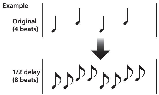
1 DELAY (One repeat sound)
This function allows a delay sound with beat of 1/8, 1/4, 1/2, 3/4, 1/1, 2/1, 4/1, 8/1, or 16/1 to be added quickly and simply. For example, When a 1/2 beat delay sound is added, four beats become eight beats. Also, by adding a 3/4 beat delay sound, the rhythm becomes syncopated.
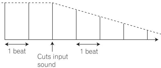
2 ECHO (Multiple repeat sounds)
This function allows an echo sound with beat of 1/8, 1/4, 1/2, 3/4, 1/1, 2/1, 4/1, 8/1, or 16/1 to be added quickly and simply. For example, when a 1/1 beat echo sound is used to cutoff the input sound, a sound in synch with the beat is repeated together with fadeout.
Also, by adding a 1/1 beat echo to the microphone, the microphone sound repeats in synch with the music beat. If a 1/1 beat echo is applied to the vocal portion of a track, the song takes on an effect reminiscent of a "round".
Example
3 Auto TRANS
In units of 1/16, 1/8, 1/4, 1/2, 1/1, 2/1, 4/1, 8/1, or 16/1 beat, the sound is automatically cut in synch with the rhythm.
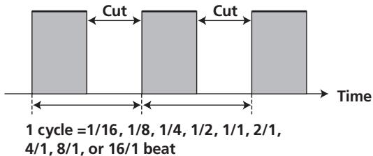
Example
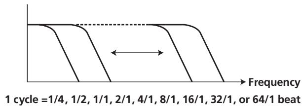
4 FILTER
In units of 1/4, 1/2, 1/1, 2/1, 4/1, 8/1, 16/1, 32/1 , or 64/1 beat, the filter frequency is moved, greatly changing the sound coloration.
Example
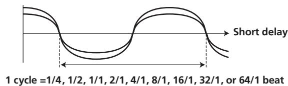
5 FLANGER
In units of 1/4, 1/2, 1/1, 2/1, 4/1, 8/1, 32/1 , or 64/1 beat, 1 cycle of flanger effect is produced quickly and easily.
Example
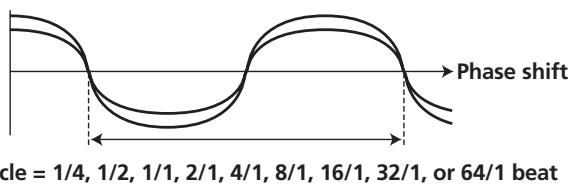
6 PHASER
In units of 1/4, 1/2, 1/1, 2/1, 4/1, 8/1, 16/1, 32/1 , or 64/1 beat, 1 cycle of phaser effect is produced quickly and easily.
Example
7 REVERB
Produces reverberation effect.
8 ROBOT
Generates sound effect resembling that produced by a robot. When ROBOT is applied to microphone sound, a voice-changer effect is produced.
9 CRUSH
Allows rapid creation of cyclically changing "crush sound effect" in beats of 1/4, 1/2, 1/1, 2/1, 4/1, 8/1, 16/1, 32/1, or 64/1.
Records sounds at 1/16, 1/8, 1/4, 1/2, 1/1, 2/1, 4/1, 8/1, 16/1 beats and plays them repeatedly.
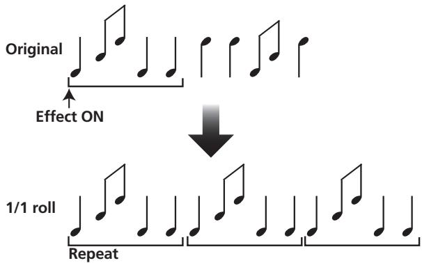
Example
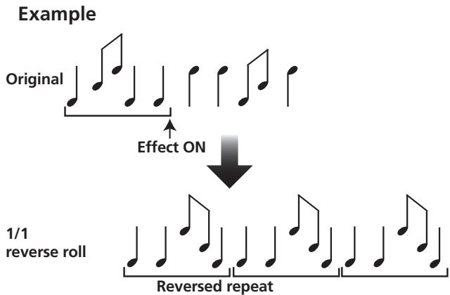
11 REVERSE ROLL
Records sounds at 1/16, 1/8, 1/4, 1/2, 1/1, 2/1, 4/1, 8/1, 16/1 beats and repeats them but in reverse order.
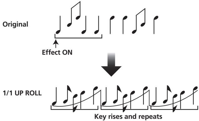
12 UP ROLL
Records sounds at 1/16, 1/8, 1/4, 1/2, 1/1, 2/1, 4/1, 8/1, 16/1 beats, and plays them repeatedly while continuously raising their pitch/key.
Example
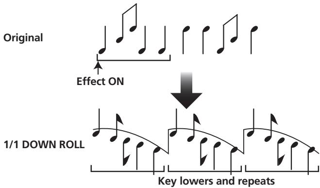
13 DOWN ROLL
Records sounds at 1/16, 1/8, 1/4, 1/2, 1/1, 2/1, 4/1, 8/1, 16/1 beats, and plays them repeatedly while continuously lowering their pitch/key.
Example
14 SEND/RETURN
By connecting a sampler or effector, a wide variety of other effects can be created.
PRODUCING BEAT EFFECTS
Beat effects allow the instant setting of effect times in synch with the BPM (beats per minute), thus allowing the production of a wide variety of effects in synch with the current rhythm, even during live performances.
1 Set BPM measuring mode to AUTO to measure BPM (beats per minute).
The BPM of the input music signal is detected automatically. Whenever power is first turned ON, the function defaults to the [AUTO] mode.
- In the event the track's BPM cannot be detected automatically, the display's BPM counter will flash.
- Measurable range: BPM=70 to 180. It may not be possible to measure some tracks accurately.
In this case, press the TAP button and input the beat manually.
[Using the TAP Button for Manual BPM Input]
If the TAP button is tapped two times or more in synch with beat (1/4 notes), the BPM will be recorded as the average value recorded during that interval.
- When BPM mode is set to [AUTO], tapping the TAP button will cause the BPM mode to change to the TAP mode, and the interval at which the TAP button is pressed will be measured.
- When the BPM is set via the TAP button, the beat multiple becomes "1/1" (or "4/1", depending on the effect selected), and the time for 1 beat (1/4 notes) or 4 beats will be set as the effect time.
- If the TIME dial is rotated while depressing the TAP button, direct BPM can be set manually.
If the TIME dial is rotated while holding the TAP button and AUTO buttons depressed, the BPM can be set in 0.1 units.
2 Set the effect selector to the desired effect.
- The display will show the name of the selected effect.
See P. 16 to 17 for details regarding the various effects.
3 Set the effect channel selector to the channel you wish to apply the effect to.
- The selected channel lights in the display's channel name area.
- If [MIC] is selected, the effect will be applied to both microphone 1 and microphone 2.
4 Press the BEAT button (, ) to select the beat multiple to which the effect is to be synchronized.
- When is pressed, the beat count calculated from the BPM is doubled, and when is pressed, the beat count calculated from the BPM is halved (some effects also allow "3/4" setting).
- The multiple of the selected beat (parameter 1 position) is displayed in seven sections on the display (see P. 12).
- The effect time corresponding to the beat's multiple is set automatically.
Example: When BPM = 120
1 / 1 = 500ms
1/2 = 250 ms
2 / 1 = 1000ms
5 Set the ON/OFF button to ON to enable the effect.
Each time the button is pressed, the effect alternates ON/OFF (whenever power is first turned ON, the function defaults to OFF).
- The ON/OFF button flashes when the effect is ON.
Parameter 1
Rotating the TIME (PARAMETER 1) dial adjusts the temporal parameter (time) for the selected effect. (With some effects, this is used for adjustments other than time parameters.)
See P. 20 for details regarding the effect on parameter 1 of rotating the TIME (PARAMETER 1) dial.
Parameter 2
Rotating the LEVEL/DEPTH (PARAMETER 2) dial adjusts the quantitative parameter for the selected effect.
See P. 20 for details regarding the effect on parameter 2 of rotating the LEVEL/DEPTH (PARAMETER 2) dial.
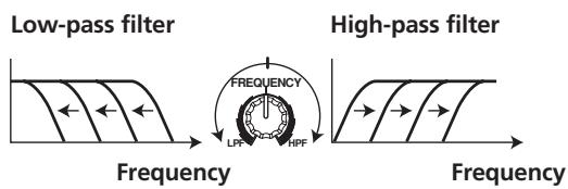
The filter frequency is shifted, resulting in strong changes to the tone.
Rotating the dial to the right produces high-pass filter effects, while rotating the dial to the left produces low-pass filter effects.
The manual effector is linked to the FREQUENCY dial. The output sounds of the manual effector become the input sounds for the beat effect.
- When the beat effect type is set to ROLL, REVERSE ROLL, UP ROLL, or DOWN ROLL, the beat effect's output sound becomes the input sound for the manual effector.
1 Press the FILTER button so that it flashes.
- Confirm that the FILTER button flashes steadily.
- When it lights, press the button so that it flashes. Each time the button is pressed, it alternates between flashing and lighting steadily.
- When power is first turned ON, defaults to steadily lighted.
2 Use the effect channel select switch to choose the channel to which you wish to apply the effects.
- The name of the selected channel will appear in the display's channel name section.
- When [MIC] is selected, the effect will be applied to both microphone 1 and microphone 2.
3 Use the FREQUENCY dial to adjust the filter's cutoff frequency.
- Rotate counterclockwise to apply a low-pass filter.
- Rotate clockwise to apply a high-pass filter.
1 Effect frequency filter
Sets the filter's cutoff frequency, allowing the beat effect to be applied to a desired frequency band alone.
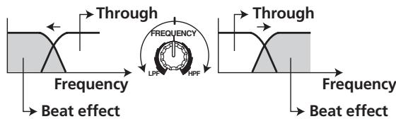
The effect frequency filter is linked to the FREQUENCY dial. The beat effect is applied only to the selected frequency band.
- The function is not supported when SEND/RETURN is selected as the type of beat effect.
1 Press the FILTER button so that it lights.
- Confirm that the FILTER button lights steadily.
- When flashing, press the button so that it lights. Each time the button is pressed, it alternates between flashing and lighting steadily.
- When power is first turned ON, defaults to steadily lighted.
2 Operate the beat effect.
For details, see page 18.
3 Use the FREQUENCY dial to select the frequency to which you wish to apply the beat effect.
- Rotate counterclockwise to apply the effect to low-range sounds only. High-frequency sounds are set to through.
- Rotate clockwise to apply the effect to high-range sounds only. Low-frequency sounds are set to through.
EFFECT PARAMETERS
Beat Effect (*1)
| Name | Beat Switch Parameter | Parameter 1 (TIME dial) | Parameter 2 (LEVEL/DEPTH dial) contents | |
| Contents | Setting Range (unit) | |||
| 1 DELAY | Sets delay time of 1/8 to 16/1 per 1 beat of BPM time. | Sets delay time. | 1 to 4 000 (ms) | Sets balance between original and delay sound. |
| 2 ECHO (*2) | Sets delay time of 1/8 to 16/1 per 1 beat of BPM time. | Sets delay time. | 1 to 4 000 (ms) | Sets balance between original sound and echo sound. |
| 3 TRANS | Sets cut time of 1/16 to 16/1 per 1 beat of BPM time. | Sets effect time. | 10 to 16 000 (ms) | Sets balance between original sound and effect sound. |
| 4 FILTER | Cycle of cutoff frequency shift is set in unit of 1/4 to 64/1 relative to 1 beat of BPM. | Sets cycle for cutoff time shift. | 10 to 32 000 (ms) | Amount of effect increases when dial is turned clockwise. |
| 5 FLANGER | Cycle of flanger shift is set in units of 1/4 to 64/1 relative to 1 beat of BPM. | Sets cycle for flanger effect shift. | 10 to 32 000 (ms) | Amount of effect increases when dial is turned clockwise. When dial is turned fully counterclockwise, only original sound is output. |
| 6 PHASER | Cycle of phaser effect shift is set in units of 1/4 to 64/1 relative to 1 beat of BPM. | Sets cycle for phase effect shift. | 10 to 32 000 (ms) | Amount of effect increases when dial is turned clockwise. When dial is turned fully counterclockwise, only original sound is output. |
| 7 REVERB (*2) | Amount of reverberation is set from 1 % to 100 %. | Sets amount of reverberation effect. | 1 to 100 (%) | Sets balance between original sound and effect sound. |
| 8 ROBOT | Sets pitch of robot sound effect within range of -100 % to +100 %. | Sets pitch of robot sound effect. | -100 to +100 (%) | Amount of effect increases when dial is turned clockwise. |
| 9 CRUSH | Cycle of crush effect movement is set to 1/4 to 64/1 relative to a single beat of BPM. | Sets cycle for crush effect shift. | 10 to 32 000 (ms) | Amount of effect increases when dial is turned clockwise. When dial is turned fully counterclockwise, only original sound is output. |
| 10 ROLL (*2) | Effect time is set as 1/16 to 16/1 relative of 1 beat of BPM. | Sets effect time. | 1 to 4 000 (ms) | Sets balance of original sound and roll sound. |
| 11 REVERSE ROLL (*2) | Effect time is set as 1/16 to 16/1 relative of 1 beat of BPM. | Sets effect time. | 1 to 4 000 (ms) | Sets balance of original sound and roll sound. |
| 12 UP ROLL (*2) | Effect time is set as 1/16 to 16/1 relative of 1 beat of BPM. | Sets effect time. | 1 to 4 000 (ms) | Sets balance of original sound and roll sound. |
| 13 DOWN ROLL (*2) | Effect time is set as 1/16 to 16/1 relative of 1 beat of BPM. | Sets effect time. | 1 to 4 000 (ms) | Sets balance of original sound and roll sound. |
| 14 SEND/RETURN | — | — | — | Sets volume of RETURN input sound. |
() When the effect channel selector is set to [CF.A], [CF.B], or [MASTER], even if the effect monitor is turned ON, if the selected channel's sound is not output to the master output, the effect sound will not be heard.
(^2) When effect is disabled (OFF), the effect sound will not be heard, even if monitor is set to effector.
MIDI SETTINGS
MIDI is an acronym for "Musical Instrument Digital Interface" and refers to a protocol developed for the exchange of data between electronic instruments and computers.
A MIDI cable is used to connect components equipped with MIDI connectors to enable the transmission and receipt of data.
The DJM-700-S/DJM-700-K uses the MIDI protocol for transmitting data about component operation and BPM (timing clock).
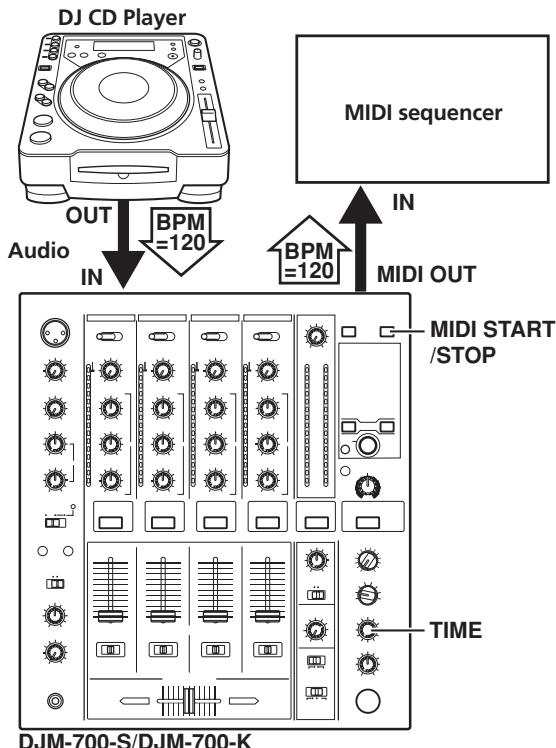
SYNCHRONIZING AUDIO SIGNALS TO EXTERNAL SEQUENCER, OR USING DJM-700-S/DJM-700-K INFORMATION TO OPERATE AN EXTERNAL SEQUENCER
1 Use a commercially available MIDI cable to connect the DJM-700-S/DJM-700-K's MIDI OUT connector to the MIDI sequencer's MIDI IN connector.
- Set the MIDI sequencer's synch mode to "Slave".
- MIDI sequencers that do not support MIDI timing clock cannot be synchronized.
- Synch may not be achieved if the track's BPM cannot be detected and measured stably.
- BPM values set with the TAP mode can also be used to output the timing clock.
2 Press the MIDI START/STOP button.
- The MIDI timing clock output range is 40 to 250 BPM.
[MIDI Channel Setting]
The MIDI channel (1 to 16) can be set and stored in memory.
1 While holding the MIDI START/STOP button depressed, set the power switch to ON.
- The display will show [CH SET] and the unit will enter the MIDI setting mode.
2 Rotate the TIME dial to select the MIDI channel.
3 Press the MIDI START/STOP button.
- Records MIDI channel. During recording of channel, [SAVE] indicator flashes.
- When recording of channel is completed, [END] is displayed.
4 Set power to OFF.
MIDI MESSAGES
| Category | Switch Name | Switch Type | MIDI Message | Commnets | |||||
| MSB | LSB | ||||||||
| CH1 | HI | VR | Bn | 02 | dd | 0 to 127 | |||
| MID | VR | Bn | 03 | dd | 0 to 127 | ||||
| LOW | VR | Bn | 04 | dd | 0 to 127 | ||||
| CUE | BUTTON | Bn | 46 | dd | OFF=0, ON=127 | ||||
| FADER | VR | Bn | 11 | dd | 0 to 127 | ||||
| CF ASSIGN | SW | Bn | 41 | dd | 0, 64, 127 | ||||
| CH2 | HI | VR | Bn | 07 | dd | 0 to 127 | |||
| MID | VR | Bn | 08 | dd | 0 to 127 | ||||
| LOW | VR | Bn | 09 | dd | 0 to 127 | ||||
| CUE | BUTTON | Bn | 47 | dd | OFF=0, ON=127 | ||||
| FADER | VR | Bn | 12 | dd | 0 to 127 | ||||
| CF ASSIGN | SW | Bn | 42 | dd | 0, 64, 127 | ||||
| CH3 | HI | VR | Bn | 0E | dd | 0 to 127 | |||
| MID | VR | Bn | 0F | dd | 0 to 127 | ||||
| LOW | VR | Bn | 15 | dd | 0 to 127 | ||||
| CUE | BUTTON | Bn | 48 | dd | OFF=0, ON=127 | ||||
| FADER | VR | Bn | 13 | dd | 0 to 127 | ||||
| CF ASSIGN | SW | Bn | 43 | dd | 0, 64, 127 | ||||
| CH4 | HI | VR | Bn | 51 | dd | 0 to 127 | |||
| MID | VR | Bn | 5C | dd | 0 to 127 | ||||
| LOW | VR | Bn | 52 | dd | 0 to 127 | ||||
| CUE | BUTTON | Bn | 49 | dd | OFF=0, ON=127 | ||||
| FADER | VR | Bn | 14 | dd | 0 to 127 | ||||
| CF ASSIGN | SW | Bn | 44 | dd | 0, 64, 127 | ||||
| CROSS FADER | CROSS FADER | VR | Bn | 0B | dd | 0 to 127 | |||
| FADER CURVE | CH CURVE | SW | Bn | 5E | dd | 0, 127 | |||
| CROSS CURVE | SW | Bn | 5F | dd | 0, 64, 127 | ||||
| MASTER | MASTER LEVEL | VR | Bn | 18 | dd | 0 to 127 | |||
| BALANCE | VR | Bn | 17 | dd | 0 to 127 | ||||
| CUE | BUTTON | Bn | 4A | dd | OFF=0, ON=127 | ||||
| BOOTH | MONITOR | VR | Bn | 19 | dd | 0 to 127 | |||
| FILTER | FILTER | BUTTON | Bn | 54 | dd | OFF=0, ON=127 | |||
| FREQUENCY | VR | Bn | 05 | dd | 0 to 127 | ||||
| EFFECT | BEAT LEFT | BUTTON | Bn | 4C | dd | OFF=0, ON=127 | |||
| BEAT RIGHT | BUTTON | Bn | 4D | dd | OFF=0, ON=127 | ||||
| AUTO/TAP | BUTTON | Bn | 45 | dd | OFF=0, ON=127 | ||||
| TAP | BUTTON | Bn | 4E | dd | OFF=0, ON=127 | ||||
| CUE | BUTTON | Bn | 4B | dd | OFF=0, ON=127 | ||||
| EFFECT KIND | SW | Cn | pc | See “PROGRAM CHANGE” below. | |||||
| CH SELECT | SW | Cn | pc | ||||||
| TIME | SW | Bn | 0D | MSB | Bn | 2D | LSB | PARAMETER 1 value; FLANGER, PHASER, FILTER, CRUSH changed to 1/2 value; minus values are converted to positive. | |
| LEVEL/DEPTH | VR | Bn | 5B | dd | 0 to 127 | ||||
| EFFECT ON/OFF | BUTTON | Bn | 40 | dd | OFF=0, ON=127 | ||||
| MIC(FADER START)(HEAD PHONES) | HI | VR | Bn | 1E | dd | 0 to 127 | |||
| LOW | VR | Bn | 1F | dd | 0 to 127 | ||||
| FADER START 1 | BUTTON | Bn | 58 | dd | OFF=0, ON=127 | ||||
| FADER START 2 | BUTTON | Bn | 59 | dd | OFF=0, ON=127 | ||||
| MIXING | VR | Bn | 1B | dd | 0 to 127 | ||||
| LEVEL | VR | Bn | 1A | dd | 0 to 127 | ||||
| MIDI | START | BUTTON | FA | ||||||
| STOP | BUTTON | FC | |||||||
PROGRAM CHANGE
| MSB | LSB | |||||||
| 0 | 0 | EFFSEL2 | EFFSEL1 | EFFSELO | EFFCH2 | EFFCH1 | EFFCHO | |
- EFFECT SEL BEAT
| EFFSEL2 | EFFSEL1 | EFFSELO | |
| 0 | 0 | 1 | DELAY |
| 0 | 1 | 0 | ECHO |
| 1 | 0 | 0 | TRANS |
| 1 | 1 | 0 | FILTER |
| 1 | 0 | 1 | FLANGER |
| 1 | 1 | 1 | PHASER |
| 0 | 1 | 1 | REVERB |
| — | — | — | ROBOT |
| — | — | — | CRUSH |
| — | — | — | ROLL |
| — | — | — | REV ROLL |
| — | — | — | UP ROLL |
| — | — | — | DWNROLL |
| — | — | — | SND/RTN |
| 0 | 0 | 1 | 1 |
| 0 | 1 | 0 | 2 |
| 0 | 1 | 1 | 3 |
| 1 | 0 | 0 | 4 |
| 1 | 0 | 1 | MIC |
| 1 | 1 | 0 | CF.A |
| 1 | 1 | 1 | CF.B |
| — | — | — | MASTER |
SNAPSHOT
Once the DJM-700-S/DJM-700-K is setup with parameters for a given purpose, that set of parameters can be recorded as a snapshot. When snapshot of the current status is recorded, all messages for control change and program change are transmitted. Hold the MIDI START/STOP button depressed to send the snapshot.
MIDI ON/OFF
Use the MIDI ON/OFF button to control whether the MIDI control signal is generated. The default condition is MIDI OFF. Even when MIDI OFF is selected, however, timing clock and snap shot functions are supported.
TROUBLESHOOTING
Incorrect operations are often mistaken for trouble and malfunctions. If you think there is something wrong with this component, check the points below. Sometimes the trouble may originate from another component. Thus, also check the other electrical appliances also in use.
If the trouble cannot be rectified even after checking the following items, contact your dealer or nearest PIONEER service center.
| Symptom | Possible Cause | Remedy |
| No power | ·The power cord has not been connected. | ·Connect to power outlet. |
| No sound, or sound volume is too low. | ·Input selector is set incorrectly. ·Connection cables are connected incorrectly, or connections are loose. ·Jacks or plugs are dirty. ·The rear panel master output attenuator switch (MASTER ATT) is set to -6 dB, etc. | ·Set input selector to playback component. ·Connect correctly. ·Clean soiled jacks/plugs before connecting. ·Adjust rear panel master attenuator switch (MASTER ATT). |
| No digital output. | ·The digital output sampling frequency (fs) does not match the specifications of the connected component. | ·Set rear panel sampling frequency selector to match the specifications of the connected component. |
| Sound is distorted. | ·Master output level is too high. ·Input level is too high. | ·Adjust master output level (MASTER LEVEL) dial or the rear panel master output attenuator (MASTER ATT) switch. ·Adjust the TRIM dial so that the input level approaches 0 dB on the channel level indicator. |
| Cross fader doesn't work. | ·CROSS FADER ASSIGN switch setting ([A], [THRU], [B]) is incorrect. | ·Correctly set the CROSS FADER ASSIGN switch for the desired channel. |
| Can't perform fader start with CD player. | ·The FADER START button is set to OFF. ·Rear panel CONTROL jack is not connected to CD player. ·Only the rear panel CONTROL jack is connected to the CD player. | ·Set the FADER START button to ON. ·Use a control cable to connect the CONTROL jacks of mixer and CD player. ·Connect both the CONTROL jacks and analog input connectors. |
| Effects don't work. | ·Effect channel selector setting is incorrect. ·Effect parameter 2 adjust dial (LEVEL/DEPTH) is set to [MIN]. | ·Correctly select the channel on which you wish to apply effects. ·Adjust the effect parameter 2 adjust dial (LEVEL/DEPTH). |
| External effector doesn't work. | ·Effect selector is not set to [SND/RTN]. ·Effector is not connected to rear panel SEND/RETURN connector. ·Effect channel selector is set to incorrectly. | ·Set effect selector to [SND/RTN]. ·Connect effector to the rear panel SEND/RETURN connectors. ·Use the effect channel selector to select the audio source to which you wish to apply the effects. |
| Sound from external effector is distorted. | ·Input level from external effector is set too high. | ·Lower the output level of the external effector. |
| BPM can't be measured. Measured BPM value is incorrect. | ·Input level is too high, or too low. ·BPM may not be correctly measurable with some tracks. | ·Adjust the TRIM dial so that the input level approaches 0 dB in the channel level indicator. ·Adjust other channels as well so that the input levels approach 0 dB in the channel level indicator. ·Strike the TAP button to set BPM manually. |
| The measured BPM value is different from the value published with the CD. | ·Some differences may occur due to differences in BPM detection methods. | ·No remedy is necessary. |
| MIDI sequencer can't be synchronized. | ·MIDI sequencer's synch mode is not set to "slave". ·MIDI sequencer is not supported type. | ·Set MIDI sequencer's sync mode to "slave". ·MIDI sequencers that do not support MIDI timing clock cannot be synchronized. |
Static electricity or other external interference may cause the unit to malfunction. To restore normal operation, turn the power off and then on again.
SPECIFICATIONS
1 General
Power source AC 220 V to 240 V, 50 Hz/60 Hz
Power consumption 33 W
Operating temperature +5^ C to +35^ C
Operating humidity . . . . . . . . . . . . . . . . . . . . . . . . . . . . . . . . . . . . . . . . . . . . . . . . . . . . . . . . . . . . . . . . . . . . . . . . . . . . . . . . . . . . . .
Weight. 6.6 kg
Maximum dimensions 320 mm (W) x 378.4 mm (D) x 107.9 mm (H)
2 Audio section
Sampling rate 96 kHz
A/D, D/A converter 24 bits
Frequency response LINE 20 Hz to 20 kHz
MIC 20 Hz to 20 kHz
PHONO 20 Hz to 20 kHz (RIAA)
S/N ratio (at rated output)
LINE. 104 dB
PHONO 94 dB
MIC .82 dB
Distortion (LINE-MASTER 1) .0.005%
Standard input level/Input impedance
PHONO 2 to 4. -52 dBu/47 kΩ
MIC 1, MIC 2. -52 dBu/22 kΩ
LINE, LINE/CD 1 to 4 -12 dBu/22 kΩ
RETURN -12 dBu/47 kΩ
Standard output level/Load impedance/Output impedance
MASTER 1. +8dBu / 10k /22 or less
MASTER 2. +2dBu / 10k /10
REC. -8dBu / 10k /10
BOOTH +2 dBu/10 kΩ/22 Ω
SEND. -12 dBu/10 kΩ/1 kΩ
PHONES +8.5 dBu/32 /22 or less
Rated output level/Load impedance
MASTER 1. +25dBu / 10k
MASTER 2. +20dBu / 10k
Crosstalk (LINE) .82 dB
Channel equalizer response
HI. -26 dB to +6 dB (13 kHz)
MID -26 dB to +6 dB (1 kHz)
LOW. -26 dB to +6 dB (70 Hz)
Microphone equalizer response
HI. -12 dB to +12 dB (10 kHz)
LOW. -12 dB to +12 dB (100 Hz)
3 Input/output connector systems
PHONO input connectors
RCA pin jacks 3
CD input connectors RCA pin jacks 2
LINE input connectors RCA pin jacks 3
MIC input connectors
XLR connector. 1
Phone jack (Ø6.3 mm) 1
RETURN input connectors
Phone jacks (Ø6.3 mm) 1
MASTER output connectors XLR connectors 1 RCA pin jacks 1
BOOTH output connectors
RCA pin jacks 1
REC output connectors RCA pin jacks 1
SEND output connectors Phone jacks (06.3 mm) 1
DIGITAL coaxial output connector
RCA pin jack 1
MIDI OUT connector 5PDIN 1
PHONES output connector Stereo phone jack (Ø6.3 mm) 1
CONTROL connector
Mini phone jacks (Ø3.5 mm) 2
4 Accessories
Operating Instructions 1
Specifications and appearance are subject to change without notice.
FONCTIONS DES EFFETS 16
PRODUCTION D'EFFETS DE BATTEMENT 18
UTILISATION DU FILTRE MANUEL 19
UTILISATION DU FILTRDE FREQUENCE D'EFFET 19
PARAMETRES DES EFFETS 20
RéGLAGES MIDI 21
SYNCHRONISATION DES SIGNAUX AUDIO A UN
SEQUENCEUR EXTERNE, OU UTILISATION DES
INFORMATIONS DU DJM-700-S/DJM-700-K POUR
CONTROLLER UN SEQUENCEUR EXTERNE 21
MESSAGESMIDI 22
CHANGEMENT DE PROGRAMME 24
PUPITRE D'EXPLOitation
FONCTIONS DES EFFETS
Publication de Pioneer Corporation.
© 2007 Pioneer Corporation.
CONNETTORI DI USCITA 7
A PROPOSITO DEI CONNECTORI MIDI. 8
COLLEGAMENTO DI MICROFONI E CUFFIE 8
Distorsione (LINE-MASTER 1) .005%
Crosstalk (LINE) .82 dB
LOW. 26 dB a +6 dB (70 kHz)
HI. .12 dB a +12 dB (10 kHz)
LOW. da -12 dB a +12 dB (100 Hz)
Copyright © 2007 Pioneer Corporation.
WAARSCHUWING NETSNOER
43 Effecttoets/indicator (ON/OFF)
BPM tellerdisplay (3 cijfers):
- CH1: Zet op [CD] of [LINE]
CH2: Zet op [CD] of [PHONO].
CH3/4: Zet op [LINE] of [PHONO].
[Kiezen van stereo of mono]
Copyright © 2007 Pioneer Corporation.
Valor de BPM: 120 BPM
Parámetro 1:500 ms
Muito de compás: 1/1
PHONO. 20 Hz a 20 kHz (RIAA)
Copyright © 2007 Pioneer Corporation.
Todoosdedechorsreserved
(He 3acNoHry Te OxJaxJaIOuIe BeHTnIaTOpbl)
He yctanabnBaIte n3dJIe N pIoxo
PNOBETPBAAEMOM NMOEUEHNIN INB MecTe C BbICOKOBNXAHCKTOB,OTKpbITOMДNPRMOROCGNHEHORCBETA(NINCINHORO MCKCYCTBEHNORCBETA)
D3-4-2-1-7c_A_Ru
PNEUPEXDEHNE
Bo n36exaHne noXapa He np6nkaTe K
obopyoBaHIO nCTOuHKn OTKpbTOrO orHa
(HaPnMep,3axKxehHbIe CBeu). D3-4-2-1-7a_A_Ru

Ecnb bI jKnaeate yHnIMPOBaTb DaHnHOe u3dJIeNHe, He bIbpaCbHaIe ERO BMeCTe C oBuHbIM 6bIToBbIM MycopoM. CyuIcTeBvET OtJEBNaHcStcema C6Opa IcNObIaBOAHbX 3NeKtPOHHx u3dJIeN B COOTBcETBm C 3aKOHOaTeJIbCTBOM, KOTopar npDeONNArae cOoTBcTBeYooHee oBaepaHne, BO3BPAT n NepepaObTKy.
AchthbIe KIHNHTB-CTPAHua-HEXAE EC, 1BJIeauHcIINu HOpBERnM OY6CNEIaHTo BO3BaPauTb IIONLOB3OBAHbIe 3EKNKTPOHNbIE 3NEDIe B COOTBTCTUOUIyue NtKHyCbI sObeIu nIi dIepey (pni oNkouy cXDOHOHOBOR i3ENIDJI).
BCTpaanh, he nepeieCnHbIX bIeIe, IJIaIIOJIyENHINHOFOPMaIM O npabINbIbIX cNtco6oax yTIINHAZIMO 6oaPaaIteB B COOTETCTBYOUIE YUPEKJENHI.
IOCTYNAI TAKIM OBP3AOM, Bbl MOKETE 6bTb YBEPEHb I TOM, YTO YTNII3KpYEbMI pOJyKT 6yET COOTBETCTBYUOUMI 6oBa3OM 6oBa60TAH, nepeaB H COOTBETCTBHyOUI MnyHK T N pepea60Tah 6e3 BO3MOKbHbX HeraTINBbX hocneTcBNI dJIr OKpyKaHOUe CpeB I N3DOpOBBy IIOJe. K058 A
Pn3KcNpIyatau nn DaHNO H3denni Co6bIOaIte HNCTpykU, KacaIoUncE paOboero HaprrKeHH N.T.I. pacNoJooKeHHbIe Ha nDhe yCtpoIcTba. D3-4-2-2-4_Ru
Данhoeиндени COOTBETCTBYET ДИректibe no Hn3kOMу habprajekhno (Low Voltage Directive) 2006/95/ECи EMC Directive 2004/108/EC.
D3-4-2-1-9a_A_Ru
EcnBnIkaIshypaIHTaHnI3dEInnHe COOTBeCTByET IMeUoIeC3IKeTpopo3eTke,BNKy CneJyEt 3aMeHNb Ha NODxOJaUyIO K po3eTke.
3aMeHa n yctaHOBKa BnIKn DoJNkHbI npOM3BODITbC TOpIbKO KBAINΦMnIPoBaHHbIM texhKOM. OToCoeDInHHeAOT KaBEn BnIka, pOKnIOUeHHaN K PO3eTKE, MoKET Bly3aBt TB JxKeNoe nopAkeHe 3NeKTPnueCKM TOKOM. Iocne ydaJIeHn BnIKn YtunImnpyiTe ee DoJNkHbIM o6pa3OM. ObOpyDoBaHne CnEduyET OTKnOuAtb OT eNkTPOceTIn, INBleKaeBnIKy KaBEn NITaHn In 03eTkn, eCNl OHO He 6yDet INcONb3ObaTcB YeTHeHne DOnIrTO BpeMeHn (HanpImep, ECNI Bbl ye3Kaete B OTNyCK). D3-4-2-2-1a_A_Ru
BHIMAHNE
BbiknquateIb POWER
daHHoro yCTpoiCTBa He NIOHOCbIb OTKJIHOaET erO OT 3NEKTPOcETn. Tc06bl NIOHOCbIb OTKJIHOuHTB nITAHne yCTpoCTBa, BbITaUNTE BnIKY Ka6eJn NITAHn I3 3NEKTPOsE3Kn. PO3OTMy yCTpoI CTBO CNeDyET yCTahABNIMBaTb Tak, YTO6bl BnIKY Ka6eJn NITAHn MOxHO 6bILO JERKO BbITaUNTe b3 pO3eTkn B Vpe3BbUaHbIX o6CToRtEnbCTbX. Bo n36BeJHAne NOXapa CNeDyET nB3NeKATb BnIKY Ka6eJn NITAHn I3 pO3eTkn, eCNI yCTpoI CTBO He bSyet NCNOlb3OBAbTCB R TeEHENe DOnIORo BpEmEH (Hapmep, eCNI BbI Ye3Kaete B OTNyck).
D3-4-2-2-2a_A_Ru
PNEyPPEKDEHNE
DaHHoe o60pOboBaHne He ABnIeTcB OBOHePOnHOuCaEMyBIM.Bo n36ExKaHne NOxkapa IINnpoAeHHN 3NEKTPnueCKm TOKOM He NOMEuaIte pRdOM C o60pyOboAHnEM EMKoCTnC JNIOKoCTMn (HaNPmep, Ba3b, ZBeTOUHbIe rOpkN) H DeOnyckaTe nonaDAnHn Ha Hero Kanelb, 6pb13r, DOxJ4-2-1-3_A_Ru
OB3ATEJIbHAI BHTNJLAH
Ipyu yctahOBke ycTpoCTBa o6ceNeBte OocTeaOHyoe IpocTpaHCTBO IyBENTnIaIIN BO m36exKaHne NObIiSeHnIe TMpePaTypbI BHTpn YcTPOCTBa (He MeHee 5 CM c3aIIn N no 3 CM cneBa n cnpBa).
PNEyUNPEXKDEHNE
B Kopnyce yctpojctBa Hmeotc 7eenni n OTBePCTnI dIe BENTNIaIIuIN, O6ecneuNbAIOue HadeJNHy paoTy 3dEJIuN 3auiuaIOUe 0r OT nepeRbe.Bo n36ExKaHHe NoXapara 3tN OTBeTn Hn B Kcem cnyae He cIeJyET 3akpbIBaTb IIN 3acNOHTb DpyrIMN IpEMcTAMn (ra3eTaMn, CkATEpTMn N UToPam) IN YcTaHaBnBAbTN bO6OpDobAHNe Ha TOnCTOM KOBe IN NOCTeIN.
D3-4-2-1-7b_A_Ru
MEPbI IPEIOCTOPOXHOCTN IPIN OBPAUHIN C KABEJEM IITAHIN
Держине кабел nb nittahna 3a bInky. BbHIMmaBnky n3 3neKtropo3eTkn, HNKOTda He TnHTne 3a cam Ka6elb, NIKOTDA He DoTparnBaItecBo ka6elЯ nittahna BlaxkHbIM pykam, Ta kak 3TO MoKet cTaB prNCHIO KOPOTKO 3aMbKaHHaNHa I npaxenHa 3neKtprueckm ToKOM. He DOnyckaTe yCTAHOBKn Ha Ka6elb nittahna Camoro npOrrpblBaTeJI, PpeMeTOB Me6elNi T.n., a TAKKe erO 3aUeMLeHn. He DonyckaTe C8a3bBAHnA ka6elb By zE9I nIIe erO cyNTbBAHnC dpyrHMn Ka6elMa. Ka6eln nittahna CNeDyET pOKlndlbAtb B tAnX MeCTax, rDe BO3MOxHOCTb HAcTyNITb Ha NIX 6yDet MAnOBepoARHOI. TOpBXeHNb Ka6elb nittahna MoKet cTaB prNCHIO B0rOpaHn IIN Nopaxhene 3neKtprueckm ToKOM. IpeNooiueckn npOBepaIte Ka6elb nittahna. EcnI o6hApYkntcR erO nobexdHeNe, O6pArITceB B 6nKaiuIin cepBnchIy ceHtp, yONHOMOeHHbI KOMpanHei Pioneer, nII K CBOeMy dInepy no NOBOy erO 3aMEHb. S002_Ru
COДЕРЖAHNE
ПОВЕРKAHAJIINЧИ ПИНДLEХHOCTEN 4
MEPbI PPEIOCTOPOXHOCTN PNI OBPAAUEN C UCTPOINCTBOM 4
MecTo yctaHOBKn 4
YxOJ 3a yCtpoiCTBOM 4
ФУHKUHOHAJIbHbI EOCOSEHHOCTN 4
ПОДКЛЮЧЕНЕ ПУЛБТА 5
KOMMYTAIOHHA IIAHEJIb 5
IIOJKJIOUeHNE BXOIOB 6
IIOJIKJIIOUeyHNE BHEIHINX ΘΦΦEKTOPOB, BBIXOHNBIE PA3bEMbl
IIOJKJIOUeHNE MIDI-KOMIOHEHTOB 8
IIOJKJIIOUEHNE MIKPOΦOHA I HAVIIHINKOB 8
IIOJKJIIOUEHNE CETEBOFO IIHHYPA 8
3JIEMEHTbI NYlbTA IN IX FyHKLIN. 9
ONEPALUN C MUKUEPOM 13
3AIVCK IJIIEPA OT ΦEIIPEA 14
3ΦΦEKTbl 16
CO3ДАННИЕ PHTM-ФФЕKTOB 18
OIIPEAUINC PUYHbIM FNIJBTPOM. 19
OIIEPAUINCΦNJLTPOM YACTOTBt ΘΦEKTA 19
IIAPAMETPBIOΦΦEKTOB 20
HACTPOIKA MIDI-UNHEPΦEÇA 21
CINHXPOH3AIII AYINOCIHAGIOB C BHEIIHHM CEKBHEPCOPM I NCIOJIb3OBAHNE IHΦOPMAIINC IIYJIbTA DJM-700-S/DJM-700-KДЛЯ YIPABJIEHNIA
BHEIIHHM CEKBEHCOPOM 21
MIDI-COOBIIEHHN 22
H3MEHEHNE IPOΓPAMMBI 24
COXPAHEHNE IIAPAMETPOB 24
MIDI ON/OFF 24
YCTPAHEHNE HENOJAOK 25
MEPbl IPEIOCTOPOXHOCTN IPNOBPAUSEHIN C UCTPOICTBOM
MecTo yCTaHOBKn
YcTaHaBnBaIte YcTpoIcTBo BXopoO BoHTnIpyEmOM MecTe, rKe OHO He 6yDet NOpBepraTbCRA BO3JeICTBnIO BbICOKNX TemNepaTpI n BlaXHoCTn.
- He yctaHaBJIbBaIte yctpoiCTBO B tAKHX MecTAX, Ie Ha HrE0 6yDyT IIOnIaIaTb IIpMBye COJIHeHbIe JIyH, a TaKKe He yctaHaBJIbBaIte erO OKIO IIJHT I paIHaTOPOB OTOIIJIeHH. N36bIToUHb IHaIpeB MoKET He6JIaIooPiYTHo IOBJIaHTb Ha KOpIyc I Ha BHyTpEHHne KOMIOHEHTb yctpoiCTBa. YcTaHOBA yctpoiCTBa B cbIpom HJIN 3aIIbJIeHHOM MeTe TAkKe MOrYT IIpNBecTH K IIOLOMKe yctpoiCTBa HJIN K HecUCAthOMy CJIyauIO. (H36eRaIte yctaHOBKn yctpoiCTBa BOJIH3N IIJIHTb, Ie Ha HrE MOrYT Bo3JeCTBOBaT rapB, Iap H TeIIIO OT IIJIHTb.)
- EcIn yctpoCTBO yctaHaBJIbBAeTcB HByTpN HeCyIeIo KOpIyCa HIN B Ka6Hnke IIN-DJKe, TO He IOnIpyckaIte KacaHHy yctpoCTBa CO cTeHAMN HIN C IpyHM O6OpYIOBaHHeM, IIOCKOJIbKy 3TO yXyDIIHT YCIOBnBEHTNIJIaIIH.
YxOД 3a yCTpOиCTBOM
- TTo6bI cTHpaTb C yctpOcTbA IIbIb I rpy3b, HcIOJIb3yIte IIOJIropOBoCHyIO TkaHb.
- EcJIN IOBepxHOCt b yctpoCTBa cHJIbHO 3aqr3HeHa, TO IPOtpTe erO MRAKoT KcAHbIO, CMOeHHo KaKM-JIHO HeHTpaJIbHBIM MOIOIHm CpeICTBOM, pa36abJIeHHbIM BOIOB 5-6 pa3, H xopoIO O tKaTOI. PocJIe 3TOrO IPOtpTe yctpoCTBO eIe pa3 cyXoT kAHTbIO. He hCIOJIb3yIte BOC JIA Me6eJIH NIIH YNCTaIIne CpeICTBa.
- HnKorJa He HaHocHTe pactBOpHTeJIH, 6eH3HH, a3pO30JbHbIe HHcEKNiDbl HJIN KaKHe-JIn6o DpyTHe XHMUeCKHe BWeIecTBA Ha cAmO yCTPOHCTBO H He NcIOJIb3yIte HX B6JIH3N HeFO, IIOCKOJIbKy OHN MOrTy IIpHBecTHN K IopYe IIOBepxHOCTH.
BbICOKoe KaueCTBO 3Byka
AHaIIOROBbIe CnHbI IpePeIaHO TcIIO MaKChMaJIbHO KOpOTKm IeIIM I Ipeo6pa3yOITcB IIΦpOB0I ΦOpMat C aCTOToI JNCKpeTn3aIIIN 96 KII BbICOKOKaueCTBeHHbIM 24- pa3prIbIM aHaIIOr- IIΦpOBbIM Ipeo6pa3OBAteJIeM. B pe3yJIbTaTe 3TOrO CnHbJIbIOCTyIaIOT Ha KaKaJIbI INΦpOBORo MKNIIHNPOBaHnC HaNBBICIIIM KaYeCTBOM.
MnKIIHPOBaHHe IpoH3BOIDTCs 32 -pa3pIINbIMIPOIEccopOM IIΦpOBbIX CNTHaJIOB, IIO3BOJIHOIIHM IIOJIHOCTbIO yCTpaHHTb KaKHeJIIN6O IOTepn KaueCTBa.
AIIIapaTpypa 3MeIeHa B KOpIyce BbICOKoJ JecTKocTH, OcHAIeHHOM MOIHbIM 6JIOKOM IITaHnH IN DpyrHM N TexHOJIOrHueCKHM pa3pa6OtKaHM, 06ecIeHuBAIOUHM MBICOKoKAYeCTBeHHoe BOCIIPOH3BVeIeHHe IN peaIIN3OBaHbIMN B DJM-1000, YTO rapaHTpyeT MaKCHMaJIbHO YIcTbI IN MOIHbI KJIy6HbI 3ByK.
PcHNoΦnIbTp
JaHHbI IyJIb TcOHaIIeH pyuHbIM 9ΦΦeKToPOM, IIO3BOJIHOIIHM 6oJIe HHTyTHBHO C03dAaTb 9ΦΦeKToB, YTO paIINpReT dHaIIa3OH BO3MOKHOCTe IJIA HrPbI dN-DKeJ. KpOME TOGO, KOM6HnIHg 3THX 9ΦΦeKToB C pHTM-9ΦΦeKtAMH (beat effects) IIO3BOJIaER IOIyHTb eIIE 6oJIe EIIHPOKNI DHaIIa3OH 9ΦΦeKToB, YTO OTKpbIbAeT OPGMH IIOTEHIIaJI IJIA C03dAHHaPa3JIHbHbIX peMHKCOB H HrPbI dN-DKeJ.
PHTM-3ΦΦeKTB1
2 KoHTpoIbHbIe BbIXoIbI BOOTH [Ka6uHka dN-dJxEa]
Pa3bEm TIIA RCA KOHTPOJIbHOr BO bIXOJa B Ka6HKnY Dn-ⅡJKeJ. YpOBeHb CnHHaJIa Ha 3TINX pa3bEmax yCTaHaBJIHBaETcO TDeJIbHO peyJIaTOPOM BOOTH MONITOR LEVEL, He3aBHcHMo OTOIIOJKeHHpeyJIaTOpa MASTER LEVEL.
3 BbIXoDbHa 3aInCb (REC)
Pa3bEmB RCA IJIY BbIOJa cHrHaJa Ha 3aINcB.
4 BxOdbI PHONO [3ByKoCHnMaTeJIb]
BxOJIHbIe pa3bEmbI RCA, IIpeJHa3HaueHHbIe IJIa IIOJIKIHOeHHa 3ByKOCHMATEJI (MM [c IOJDBHXHBIM MaHHTOM]).
He HcIIOJIb3OBAt bIJI IOJaUH cIgHaJIOB JInHeHOrO yPoBHn.
5 Bxodbl LINE [JIInHeHbI BxO]
BxOJIHbIe pa3bEmbI RCA, IIpeHa3HaueHHbIe IJIaIOaHcNrHaJIIOB JInHeHOro ypOBH.
HcIOJIb3yIOTcIJIIIOIKJIIOUeHHaKacCETHbIXIeKIIINpyrTOO6OpYIOBaHnIcJIINHeiHbIMBbIXoJOM.
6 BxodbCD [CD-neeep]
BxOJIHbIe pa3BeMbI RCA, IIpeHa3HaueHHbIe IJIaIIaUN cIHraIOB JInHeHOro yPoBHJ.
HcIOJIb3yIOTc IJIIOJIKJIOueHnI DJ CD-IIIEepa HJIIN dpyTHX KOMIOHEHTOB C JINHeiHbIMN BbIXOdAMN.
7 Pa3beMbI CONTROL [YnpaBneHne]
MaIIOra6apHTbI pya3bem dHaMeTpOM 3,5 MM. HcIIIOJIb3yETcRdIJI IOIKJIIOUeHnK BXOy yIpaBJIeHn DJ CD-IIeepa Pioneer.
EcJIN 3OT pa3bem IIOJKIIOUeH, TO ΦeIJIep IyJIbTa DJM-700-S/DJM-700-K MoKHO HcIIoJIb3OBAt bIJI OIIepaIHI NysKa/oCTaHOBKn DJ CDIIeepa.
8Два мнкрфонhhIx Bxoja (MIC 2)
HcnoJIb3yETcIJIa IIOKJIHOeHHa MHKPOΦOHOB CO IIITEkepOM TIIHa Phone.
9 KOHTaKTHbIe pa3beMbI 3a3emJIeHnra CnHaJa (SIGNAL GND)
YMHebIaIOT NOMEXH IIPIH IOKJIIOueHHN IPOINrPBbATEJIb BHHJIIOBbIX IIIACTIHOK(《BeptyIIeK>)
10 Pa3bem MIDI OUT [BbIXoM MIDI-cnHana]
BbIXoHoi pa3bEm TnIa DIN.
HcnoJIb3yETcraIINIOKJIHOeHHaIpyTHX MIDI-KOMIOHeHTOB (cm. ctp. 21).
11 Pa3bem DIGITAL OUT [LunpOboB BbIXo]
IuΦpOBoKoakchnaJIbHbI BbIXoTIIaRCA.
TlaBnIuΦpOBoaayIOBbIXoJ.
12 IpeeknouateIb BbIbopa qactotbl DnckpeTn3aun (fs 48 k/ 96 k)
HcnoJIb3yetyaIy yctaHOBKn YacToTb IuNckpeTHaIIIN IuΦpOBOrOBbIXoJa C bIb6Opom Ha 96 KΓI/24-pa3prIbIbIbIbΦopMaT IJIH 48 KΓI/24-pa3prIbHIbΦopMaT.
- IpepeI IN3MeHHeHem IOJIOKeHnE 3TOrO IpepeKJIHOaTeJIe BbIKJIHOaYte IINtAHHe.
13 Pa3bembl RETURN [Bo3bpa]
BxOJIbTHIIaPhoneIHaMaTePOM6,3MM.
HcIOJIb3yIOTcIJIa IIOKJIIOUeHnB bIXoIOB BHeIIHHx 3ΦΦeKTOPOB HJIaHApIOrHnHbIX yCTpoIcTB.
Ecln IIOJI KIHOeH ToJIbKO JIeBbI KaHaJI (L), TO OH OJHObpemEHNOIJaETcN Ha IIpaBbI KaHaJI.
14 BbIXoDbI SEND [HanpaBnTb]
BbIXoIbTIHa Phone IHaMeTpOM 6,3 MM.
HcIOJIb3yIOTcIJII IIOKJIIOUeHHB XOBIOB BHEIHINX 3ΦΦeKTOpOB HJIn aHaIIOHUYHbIX KOMIOHOHTOB. EcIJI IOIKJIIOUeH TOJIbKO JIeBbI KaHaJI (L),TO BbIOJNTcM OMOΦOHHueckn CnHJaI L+R (JIeBbI + npabBk KaHaJIbI).
15 IpeeknouateNB ocna6neHn ypOBn rnaBHO rBixOda (MASTER ATT)
HcnoIb3yetyraJIOocJIa6JIeHHy yPOBHeI rIaIBhIX BbIXoOB 1 n2. OcJIa6JIeHne MoKHO yCTaHOBHTb Ha 0 dB, -3 dBn -6 dB.
16 BbIXOdbI MASTER 2 [ΓlaBbIy BbIXoD 2]
HecmmMeTpHbIyBxOd,pa3bEm RCA.
17 Pa3bembl MASTER 1 [Главны Вьхов 1]
СHMМЕТЧИБМ BыJOOD TиЯ XLR (IITbIbKOBь).
- IIpn HcIOJIb3OBAHH HnHpya co IITeKePOM TnIIra RCA IIIOJIb3OBAteJIIM peKOMEHdyeTcI IOIKJIOHaTb IITeKeP HeIOpcJeCTBeHHo K pa3bemy MASTER 2 [TJIaBHbI BbIXoI 2], He NCIOJIb3yI nepexoIHNK XLR/RCA.
18 CeTeBoI uHyp nHTaHnIa
YpOBeHb cnHnHa JbBxOJa 3aJaeTcpepyJITOpOM BOOTH MONITOR
LEVEL, He3aBCHMO OT HaCTpoH K yOBo H IJIaBHO BO BbIXoJa.
BbIXoDbHa3aNNCb
3TN BbIXOJIbI IIpeJHa3HaueHeBb IJIa BBIOJIHeHHa 3aIIHcN IyBJIHOITcRCA pa3beMaMn.
UnpoBoB BbIXoA
ДляЗТOrO ΜИнфpoBOrO KoAKChaJIbHOrO BbIXOJa HcIIOJIb3yHOTcra ьRCA. YAcTOTy IINCKpeTHaUHN MOxHO yCTaHOBITbHa 96 KΓI/24-pa3prIbHI 的ΦopMaT HJI48 KΓI/24-pa3prIbHI 的ΦopMaT B COOTBETCBH N C IOKJIIOUeHHbIM yCTpoIcTBOM.
- IpepeI IN3MeHeHEm IOJIOKeHn8 3TOrO IpepeKJIHOaTeJIy BbIKJIHOaYte IINTaHHe.
BHeuHn 3ΦΦeKToP
HcIOJIb3yra Ka6eJIb co IITKepepaMn Phone dHaMeTpOM 6,3 MM, coeINHHte pa3bEmbl SEND DJ-MHKIepa c BXoJAMn 3ΦfKeKTopa. EcIn 3ΦfKeTOp HmeeT MOHOfoHNueCkne BxOJIb, TO coeINHJaTe ToJIbKO JEBBI BVIXOJ (L) DJ-MHKIIepa. B 3tOM CJIyae Ha 3ΦfKeTOp 6yJeT IOdaBAtbcra MHKIIHPOBaHHb ayDIOCHrHaJI L+R. AHaIOIgNHbIM o6pa30M, HCIOJIb3yra Ka6eJIb co IITKepepaMn Phone dHaMeTpOM 6,3 MM, coeINHHte pa3bEmbl RETURN DJ-MHKIIepa c BVIXOAmn 3ΦfKeTOpa.
EcJIN 3ΦΦeKTop HmeeT TOJIbKO MOHOOHOHueCKn BbIXoJ,TO IIOJIKIHOaHTe K DJ-TOJIbKO JIEBBI BbIXOHOH KaHaJI. CnIHaJIbOT ΘΦΦeKTopa 6yUyt NocTyIaTb Ha JIEBBI N IpabBI KaHaJIb. IPrn HCIOJIb3OBAHH BHeIIHero ΘΦΦeKTopa IIpeKeIIOHauTeJIb 3ΦΦeKTOB Heo6XoIHMO yCTaHOBHb B IOLOJOKeHne [SND/RTN].
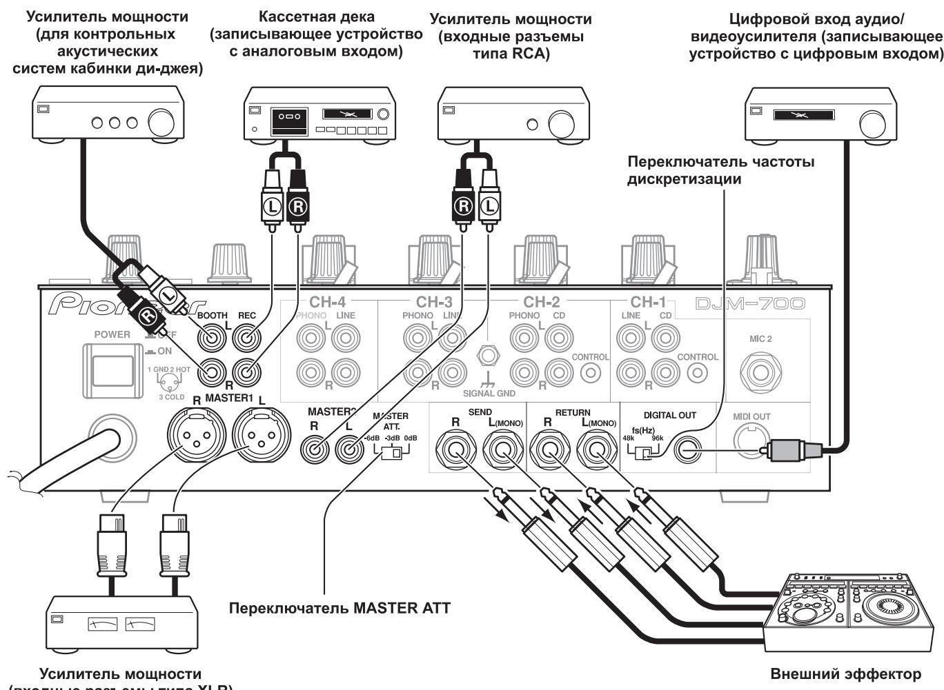
ПОДКЛЮЧЕНЕ MIDI-KOMNOHETOB
OIIHcaHHe MIDI pa3bEmOB IIpHBOIHTcHa cTp. 21.
ПОДКЛЮЧЕНЕ МИКРОФОHA И HAYSUHNIKOB
Mnkpocph
MnKpOfoH co ⅢTeKePOM TnIa XLR MoJHO IIOCoEINHHITb K pa3bemy MIC 1 Ha pa6oey (BepxHe) IanaJIH.
ГезДоMIC 2Ha KOMMyHnKaIHHOHПанeЛи МОжТИСПЛьЗОВaТьсЯ ДлЯ ПОдcoeДиНЕнг МнКрфОHA co IITeКeРOM TПпа PhoNe ДИamEтpa 6,3 MM.
- EcJIH MmKpOfoH hCIOJIb3yETc, yCTaHOBHTe IpeKJIIOUaTeJIb MIC Ha pa6oey IIaHeJI B IOJIOKeHne [ON] IIJN [TALK OVER] H NaCTpoIte peYJITop LEVEL, KaK 3TO HeO6XoJIMO. EcJIH MmKpOfoH He hCIOJIb3yETc, peKOMeHJyETc yCTaHOBHTb IpeKJIIOUaTeJIb MIC B IOJIOKeHne [OFF] IIIOBepHyTB peYJITop LEVEL B KpaIIHee IOJIOKeHne IpoTHB YacOBoi cTpeJIKN B CTOpOHY [-∞].
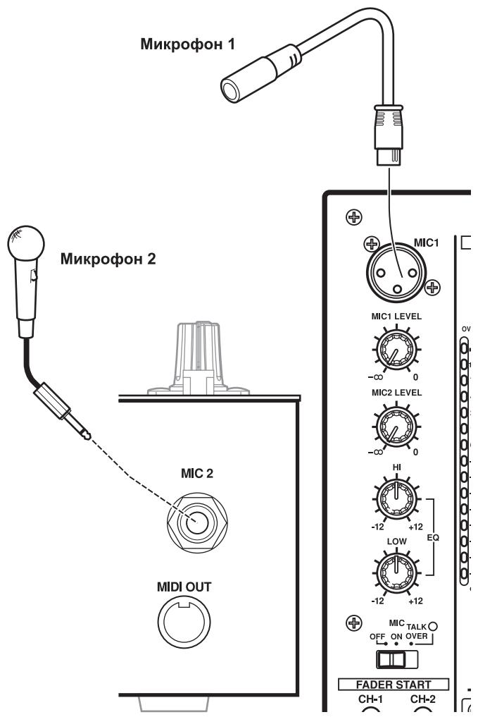
Hayushnkn
THe3IO PHONES, HaxoJIIeecs Ha BepXnei CTOpOHe pa6ooye IIaHeJIH, MOKHO HcIIOJIb3OBAtB IJIa IIOJIJIHOueHHaYIIHHKOB coCTpeofoHHueckHM IITEKePOM Phone dHaMeTpOM 6,3 MM.
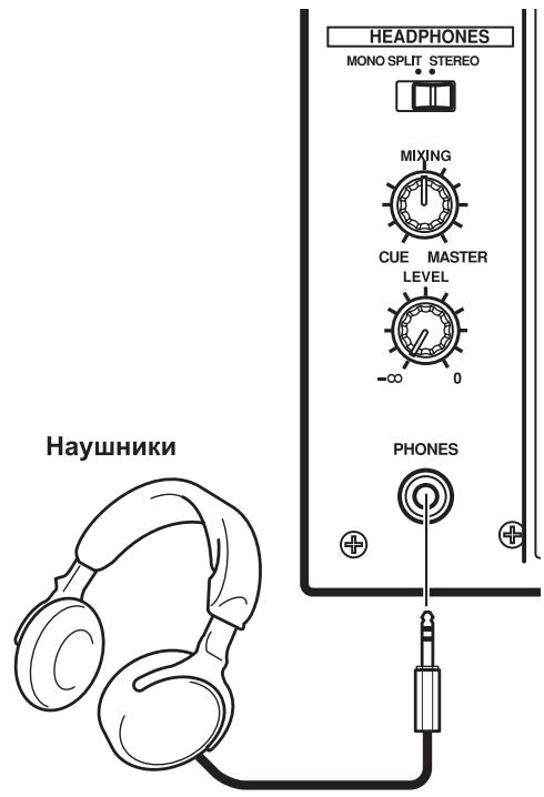
ПОДКЛЮЧЕНЕ CETEBORO SHHUPA
CeteBoi uHyp Heo6xOaMo noknouatb B nocJeHHIO oUepeB.
-ПослЕ bblIOJIHeHnB BcEx COeIINHeHnI, ПОДКЛIOUHTe CeteByIO BnIKy K cTaHApTHoI 6bIToBOI pO3ETke IpepeMeHHoro Toka.
HcnoJIb3yeTcA IIa BbI6opa BXOJa CD (aHaJIorOBbI BxOJ JINHeiHOrO ypOBH).
LINE:
HcnoIb3yeTcyaIyBaIb6opaBxoJa LINE [JIInHeiHbI BxOJ].
9 IpeeknouaTeIb BbIbopa BXOda IJIa KaHana 2 CD:
HcnoJIb3yeTcA IIa BbI6opa BXOJa CD (aHaJIorOBbI BxOJ JINHeiHOrO ypOBH).
PHONO:
HcnoIb3yeTcIyBb6opaBXOa PHONO (aHaJIorOBbI BXoI IIOKIIIOHeHnI pOnIHpBbIaTeJI BHNIOBbIX IIaCTHOK).
10 PepeknioaTeIb Bbl6opa BxOda Ina KaHaNoB 3,4 LINE:
HcnoJIb3yETcAIIBAIb6OpaBXOJaLINE(aHaIOROBbI BxOJINHeiHOrgo ypOBH).
PHONO:
HcnoIb3yeTcIyBb6opaBXOa PHONO (aHaIORObI BxOJ IIOKJIIOHeHnI pOnrPbIBaTeJI BHNIOBbIX IIaCTHOK).
11 PerynayTop TRIM [PioctpoKa]
HcnoIb3yetydIJIIOCTPOKHNyOBoNBAxOHOrO CnHnJa KaJIOrO KaHaJIa (IIpeJeIbIpeRyJInPobKN:OT:- 一 _ 0 + 9 nB, cpeINHeMy IIOJOKeHHIO COOTBeTCTByET yPoBeHb OKIo 0 nB).
12 KaHajbHbI 3KBaJau3ep, peryJrTOp BBicOKnx qactOT (HI)
HcnoJIb3yetycIJIa HAcTpoKn yOpBnBa BlicOKnx YacToT KaHaJIa (dHaJIa3OH peryJInpOBKn: ot -26 1b Do +6 1b).
13 KaHaJIbHbIy 3KbAlaJau3ep,peyJIaTOp cpeHnX qactOT (MID) IcIOJIb3yeTcI JIg HAcTpoKIn yUPOBnCpeHnIX qactOT KaHaJa (IIHaJIa3OH peYJIuPBOKn:OT-26Dbdo+6Db).
14 KaHaJIbHbIy 3KbAlaJn3ep, peryJrTop Hn3Knx qactOT (LOW)
HcIOJIb3yETcI JIg HAcTpoIKyPOBHg Hn3Knx qactOT kaHaJa
(ДиАпAZOH peryJInpObKn: ot - 26 ДБ до +6 ДБ).
15Индикаторурвяkaна
OTo6paKaeT KeYiHn IyPoBeHbIJI KAKJIOrKaHaJIa; MaKChMaJIbHbIyPoBeHbYIepKHNBaEcTBteYeHneIbYx CeKyHd.
16 KhoNkMnHmKaTopbI HEADPHONES CUE
3TN KHOIIHK HCSIOJIb3yIOTcR DA BbIbOpa HcTOUHnKa CnHaJa: c 1 IIO 4,
MASTER INIH EFFECTS, YTO6bI KOHTPOJIINPOBaTb BbIbpaHHbI
HCTOCHNK c I NOMOIIbIO HayIIHNKOB. EcIN HaKaTb HECKOJIbKO KHOIIOK
ODHOBpeMeHHo, TO BbIbPaHHbIe KaHaJIb 6ByT MKNIIHNPOBaTbc. JIO
OTMeHbI BbIbpaHHoro KAHaJa HAKMITE KHOIIky BbIbpaHHoro
HCTOCHNka eIe pa3. KHOIIKa BbIbpaHHoro HcTOUHnKa JaPko
IOIDCBeUHBAeTcR, a BCE OCTaJIbHbIe KHOIIKN 3aTeMHHebl.
17 KhoNkM/HHnKaTOpbI nycKa CD-nPeepa oT fpeiepa (FADER START CH-1, CH-2)
3TN KHOIIKN O6ecIeHbAHT cyHKIINIO Iycka/BO3BpTaK MeTKe IJIa TORO KAHaJIa, K KOtOpOMy IOIKIIOueH DJ CD-IIeep. EcJH KyHKIIIN BkJIIOUeHa, TO KHOIIKA CBeITcR. JeIeCTBNE cyHKIIIN ONpeJeIeETcR IIIOJOKeHHem IIEPeKJIIOuTeJIa CROSS FADER ASSIGN [Ha3NaHeHne KaHaIOB KpocccfeIepa].
- EcsIII IpeKJIIOHauTeJIb CROSS FADER ASSIGN yCTaHOBJIeH B IIIOJOxHeHne [A] IIIN IIIOJOxHeHne [B], To OIEpaIaII IyCsKa C HcIIIOJIb3OBAHNem ΦeIePa IprNBy3aHa K OIEpaIaII KpOccΦeIePa (I He IIpNB3aHa K KaHaJIbHOMy ΦeIePy).
- EecIIIpeKJIIOHauTeJIb CROSS FADER ASSIGN yCTaHOBJeH B IIOJIOKeHHe [THRU],TO OIIepaIIyIysKa C HcIIIOJIb3OBAHNEM fIepa IIpINBIA3aHa K OIIepaIIHH KaHaJIbHOrO fIeIdepa (H He IIpNB3aHa K KpOccfpeIepy).
18ДвижokKaHaJIbHOrофeIepa
HcnoJIb3yETcIgpeYInpOBKn yOBoBHaKaJIOrKaHaJa (HaIIa3OHpeYInpOBKn: ot - do 0 dB).
H3meHeHHe BbIXoHOrO cHrHaJa IpOH3BOJNTcB C COOTBeCTBHN cXapakTepeHcTHKO KaHaJIbHOro ΦeIepa, BbIOpaHHo IpePeKJIHOaTeJIeM
CH FADER
19ПееклочаелСROSS FADER ASSIGN [Ha3haueHne KaHaIOB KpoccpeiDEpa]
3TOT IpeKJIIOUaTeJIb IO3BOJIaTe H3NaUHTb BbIXOД KaXIOTO KaHaJIa JIN60 IIpaBoI, JIN60 JbeO bCTopoHe KpocCΦeIJIepa (ecJIN OJHO CTOpOHe Ha3NaUeHO HeCKOJIbKO KaHaJIoB, TO pe3yJIbTaTOM 6byET cyMMA KaHaJIOB).
A:
Bb6paHHbI KaHaJI Ha3HaayetcJIeBoI cTOpOHe KpocCpeIIepa(A).
THRU:
BbIXoⅡKaHaJIbHOrO ΦeIepa IpePeIaETcHa ΓJIaBHbIi BbIXoI, He IIpoXoIa Ycepe3 KpocCfeIep.
B:
Bb6paHHbI KaHaJI Ha3HaayaeTcI paBOi cTOpOHe KpocceHepa (B).
20 IpeeknouateIb xapaKtepcntkKaHaJIbHOro fepa(CH FADER)
3TOTIpeEKJIIOUaTeJIbIO3BOJIaERIOJIb3OBaTeJIIOcDEJIaTbBbI6OpH3 DBYx TINIOB IepeXoIDbIX XapaKTepHcTHK KaHaJIbHOro eJIEpa. 3Ta HAcTPOIIKa IIpIMHeHraTc OINHaKOBO IJIa KaHaJIob 1-4.
JIeBoe IIOJIOKeHHe IpeKJIIOuHaTeJIa:JaHHaI XapaKaTepHCTNka 06ecIIeHbAeT pe3Koe yBeJIHueHne yPoBnK, KOrIa KaHaJIbHbIe ΦeIep IIpH6JIINKaeTcK KpaIHeMcy IIOJOKeHHIO.
- IIpaBoE IOJOxKeHHe IpeKJIIOuAteJIa: DaHHa XapaKTePrcHTKa oBecIIeHbAeT IIaBHOe yBeJIINueHHe yPoBHg IIpi DnIKeHHN KaHaJIbHOrO feiJepa.
21 IpeeknouateIb xapaKTepeNCTnKn KpocCpeiDepa (CROSS FADER)
3TOT IepeKJIIOUaTeIb IIO3BOJIAET BbI6paTb ONDHy NTpEx IepeXoIHbIX XapakTepnCTNK KpoccfeiIepa.
JIeBoe IOJIOKeHHe IpeKJIIOuHaTeJIa:JaHHaI XapaKTePcHtKa o6ecIIeHbAeT b6IcTpoE HapactaHHe cIHHaJIa. (KaK TOJIbKO JBHXOK KpOccFeiIepa CMeIIaETcR O T CTOpOHbI [A], cIHHaJI IIOBBAIErTcR B KaHaJIe [B]).
- IIpaBoE IOJIOxKeHHe IpeKJIIOUaTeJIa: DaHHa XapaKTepnCTHka oBecIeYHbAeT IJIaIBHO E IOBbIeHHe yPOBHa CnTHaJa IpiI IpeMeIeHNN DBNKKa KpOcCfEJIepa.
CpeJHee IOJIooKeHHe IpeKJIIOuHaTeJIaDaHnHaXapaKTePcHCTNka OBeecIeunBaet IpOMeKyTOUHyO XapaKTePcHCTNky, MeKJy JIeBbIM IN IpaABbIM IOJIIOKeHHMaIIpeKJIIOuHaTeJIa.
22Движок крocфйдара
OeHbAeT BbIOI CNHaJIOB, H3NaHeHHbIX CTOpOHAM [A] I [B] BCOTBETCTBn C yCTaHOBKOI IpeKJIIOUaTeJI CROSS FADER ASSIGN, IIIN TII INepEXoHoi XapaKTEpHcTKn OIIpeJeJIaETcI IOJOKeHHem IpeKJIIOUaTeJI CROSS FADER.
23 PeryIaTOp yPoBnI IaBHO rBbIXoJa (MASTER LEVEL)
HcnoIb3yeTcndHaHacTpOKn ypOBnCnHaJa rJbHO BbIXoJa (dnaia3OH peryJInpOBKn: ot - do 0 b).
Главнь ВыхолягьяетсуСММОн снгhalIOB cIeIyUOIIHX KaHALOB: CnHaJIa,ДлЯ KOTOPOrO ПepeKJIOVAteJIeM CROSS FADER ASSIGN BbI6paHO IIOJOKeHHe [THRU];снгhalJa,IpoXoIJIeTo Qepe3 KpocCфeIeP;снгhalIOB OT MHKpoФоHa 1 И МнКрФоHa 2 (ecIIN IpepeKJIOVAteJIb 3ΦΦeKtA yCTaHOBJIeH B IOJOKeHHe [SND/RTN], TaKke ДобаBJEETcBxOД RETURN).
24 INDkaToPbI rnaBHoro ypoBHa (MASTER L, R)
3TNIOLOCKOBbIE HINHINKaTOpbI OTO6paKaHOT BIXOHOYyPoBeHbJIeBOrO (L) INIpaBOrO (R) KaHaJIoB. HINHINKaTOpbI yIepKINBaHOT MaKcHMaJIbHbIyPoBeHb CnIHaJIaB TeueHHe NByx CekyHd.
25 Perynatop 6ana hca rnaBhoro cnHana (BALANCE)
HcIOJIb3yetycIINHaCTpoIKN6aJIaHcaJIeBOrO/IpaBOrO KaHaIOB rJIaBHOrO BbIXOJa,KOHToJIbHOrO BbIXOJa,BbIXOJa Ha 3aIIINcBn IINΦpOBOrO BbIXOJa.
26 PepekJIuOaTeIb rJaBHOrO BbIXoJa MONO/STEREO.
KordaIpepeKJIIOUOaTeJIb yCTaHOBJIeH B IIOLOJKeHHe [MONO],IJIaBHBII BIXoD, KOHTpOJIbHbI BIXoD B Ka6Hky IIN-IXeR, BIXoD Ha 3aIIncbI IuΦpOBoB BIXoD BBIOJrTCB KauCeTBe MOHOΦOHNUeCKORO coUeTaHHaKaHaIOB L+R.
27 Perjntop ypOBH KOnTpOJIbHoro cnHaNo BOOTH MONITOR LEVEL
TOT peryIaTOP hCIOJIb3yETcH IJI HACTPOJKN yPOBHЯ rPOMKoCTH KOHTPOJIbHOro cHrHaJa, IOCTuJIaIOUeRO B Ka6HHky Dn-Dke.
YpOBeHb KOHTPOJIbHOrO CnIHHaJIA MOKHO peRyJIINPOBaTb He3aBHCMO OT yPOBHraJIaBHOro BbIXOJa (IHaIIa3OH peRyJIINPOBKN:OT - 0D5).
28 IpeeknouaTeIb pexmpa6oTbI HayuHnKOB (MONOSPLIT/STEREO)
MONO SPLIT:
KoГда bblópaHa KhoIIka HEADPHONES CUE (1, 2, 3, 4 IJIIN EFFECTS), BblópaHbI NCTOuHnK ayUINOCHrHaJa BBIOJNTcHa JIeBbI KaHaI. KoTda bblópaHa KhoIIka HEADPHONES CUE
(MASTER), rJaBbIy ayDIOscHnJI bYbIOJNTcyepe3 npaBbI KaHaJI.
STEREO:
HcToUHK ayDnOCHHaJa, BbI6paHHbI c IIOMOIIbIO KHOIIKN HEADPHONES CUE, BBIOJNTcB CTepeoOHueckOM BIne.
29 Peryntop Mkupepa CnHaNoB, NdaBaembIX Ha HayuHnK (MIXING)
ПиВвашенип ругл对接а п acobоч стpeЛke (К пIoJOKeHHO [MASTER]),В hayшнкax ctaHOBHTcя сьИинглЯВьхОД (TOIыКВТOMСЛУЧAE,ecINKHOIIKOH HEADPHONES CUE bIbpaH KaHaJI [MASTER]);ПиВвашенип ругл对接а пOTOBH acobоч CTpeIKN(KПIOJOKeHHO[CUE])В hayшнкax ctaHOBHTcя сьИинcoUteHne KOHTPOJIbHOrO cngHajla 3ΦΦeKTA И KaHaJa, bIbpaHHORO KHOIIKOH HEADPHONES CUE.
B cpeHHeIIOJIOKeHH6yUyt BbIBOINtbcay aYINOCnHaJIbIC KaHaIOB [MASTER] n [CUE].
30 PerynayTop ypoBna CnHaJa HayuHkoB (LEVEL)
HactpaHbAeT yPoBeHb BbIXoHOrO cHrHaJa B HauIHHKax (HnHaIa3OH peryIINPobKN:OT- - 01B).
31 THe3do DnI noDknIOUeHnHauyHNKOB (PHONES)
HcnoJIb3yETcIJIa IIOKJIHOeHnMHKpOfoHOB CO IIITKePOM TIIa Phone.
32 KhoNkN N3MeHEnHa TeMa (BEAT)
(YBeJIuHHeHne TEMHa):YdBaHbAeT BbIuNcJIeHHbI BPM.
(YMeHbIIeHHe TEMIIa):YMeHbIIaet BIDBOe BbIuNCJIeHHbI BPM. (cm. ctp. 18)
- HeKOTOpBie 9ΦΦeKTH MOrγT 6bIb 3aДaHb IДЯ TeMIIA "3/4".
IIaHEKOTOpbIX 3000KHOJIKN HcIOJIb3yOTcIJIa yHKIN, OTJINHbIX OT HAcTPOIKN TaKtA.
33 Khonka MIDI ON/OFF
YcTaHaBJIbBaetfHyHKIINIO MIDI-BbIXOJa (He BKJIIOUaIyHKeIIIO cHnHXPOHN3aIHH) Ha ON/OFF (BKJI/BbIKJI). IIpH IepBOM BkJIIOueHH INITaHH NaCTpoKa aBTOMaTHueCKN IpeKJIIOuaETcI IO yMOJIuaHHIO Ha OFF (BbIKJI).
34 KhoNka nycka/octaHOBKn MIDI-KOMnoHeHTa (MIDI START/ STOP)
HcnoJIb3yETcIJIpeIaIChnHaJIpyCKa/OCTaHOBKn IJIgΦyHKIIHH MIDI-ynpabJIeHNr (cm. ctrp. 21).
EcJIN 3Ta yHKIIIAA KTHBn3HPOBaHa, TO Ha JINCIJIe B TeueHne IByX ceKYH II IOYBJIeTcOo6IeHne [MIDI START (STOP)] [IYck/ octaHObKa MIDI-KOMIOHeHTa].
MIDI SNAP SHOT:
EcJIN KHOIIKY MIDI START/STOP yIepKHBaTb HkaToT, TO TEKUJIne IapametpbI IocbJIaHOTcHa BHeHHN MIDI-KOMIOHeHT.
35 KhoIIka pexkma n3mpeHnBPM (AUTO)
IpekeJIIOUaET MeKJy peKHMamn H3MepeHnBPM AUTO n TAP.
40 Bb6op KaHaJa, Ha KOTOpBn DeHCTByeT 3ΦΦeKT (1,2,3,4, MIC, CF.A, CF.B, MASTER)
3TOTIpeKJIIOUaTeJIbHcIOJIb3yETcIJIYBb6OpaKaHaJIa,HaKOTOpbI 6yJETJeIcTBOBaTB ΕΦΦeKT (cm. cTp.18).EcJIIN Bb6paH KaHaJI [MIC], TO ΕΦΦeKtBI JeIcTBYHTa CNrHaJIbI O6oHX MhKpOfoHOB (1 H 2).
41 Perylntop npametpa 3f0fekta 1 [TIME (PARAMETER 1)]
HcIOJIb3yETcaIJIHaCTpoiKNBpeMeHHoroIpaMaTePa BbI6paHHoro HJIbTpca (cm. ctp. 18, 20) (JIra HeKOTOpbIX 9ofoKToB HcIOJIb3yETca IJIa DpyrHX HaCTpoeK, IOMMHO BpeMeHHbIX IpaMaTePoB).
-
EcIn peYJIaTOp TIME BpaIaTb IIpH HauKaToI KHOIIKe TAP, TO BPM MOKHO yCTaHOBHTb BpyHyIO.
-
Ecln peyjITop TIME BpaIaIb TpN HauKaTbIX KHOIIkax TAP IN AUTO/TAP,TO BPM M0xH0 yCTaHaBJIbBaTb C ToUHOCTb 0,1.
42 PeryjIop npaMeTpa 3ΦΦeKta 2 [LEVEL/DEPTH (PARAMETER 2]
PeryIHypeT KOJIHueCTBeHHbIe IapamEtpyi BbI6paHHOrO 9ΦΦeKTa (cM. cTp.18,20).
43 Khonka/HHdNkATop BKJIIOUeHn/BBIKJIIOUeHn 3ΦΦeKTA (ON/OFF)
YcTaHaBJIbnaBaET BbI6paHHbI ΦΦeKT ON/OFF (BKJI/BbIKJI) (cm. ctp. 18). IIpn IepBOM BKJIIOueHIN IITaHnHa HAcTpoJa IpeKJIIOUaTeCII IO yMOJUaHHo Ha OFF (BbIKJI). KOrJa HAcTpoJa ycTaHOBJeHa HA OFF (BbIKJI), INHIMKaTop KHOIIKN RopHT. KorJa ΦΦeKTbI BKJIIOueHbI (ON), KHOIIKA MmraET.
44 Dusnnei
Iopno6hee cmOTpnte B cJeDyUoIe m pa3JeIe.
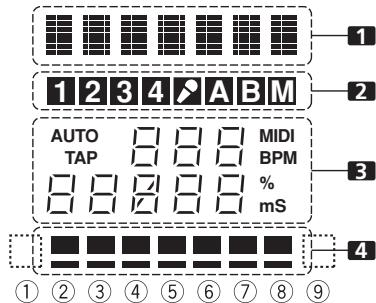
CEKUNI INCNIIER
1 Cekun Daicnpe 3fpeKTOB
TeKCTOBOДиСПЛeI(73HakOB)OTOBpaKaETHa3BaHHe 3ΦΦeKTa B COOTBETCTBHH C pInJIaAeMoT Ta6JIuIeI. KpOME TOrO, KOrJa BAIIIOJIHЯETcOJHa H3 OIIepaIiCMeHbI 3ΦΦeKTa, KaK IOKa3aHO B Ta6JIuIe,TO B TeUeHEnIByX cekyHД IOKa3bIBaIOTc COOTBETCTBYIOJIHc CHMBOJIbI, IIOJIe YerO IIHcIIeI Bo3BpaIIaIeTc K O6bIYHOMY OTOBpaKeHHIO HA3BaHnI 3ΦΦeKTa.
HdNkaTOp eDnHnU n3MepeHn (% nIms [MC]):
BbCBeHbAOTcEHNHbI, HcIOJIb3YeMbIe IJIa DAHHOrO 9ΦΦekTa.
4 Cekunr temna
OTo6paKaetIOJIoKeHHeInapaMeTp a 1 IO OTHoIeHHo K BPM (1/1 yIap). HnKHN pI rOpIT nocToHNo. KoIa 3NaueHHe InapaMeTp a 1 IIpHiNkaeTcR K IIOPOROBOMy 3NaueHHIO, To HaUNHaet CBeHTbcS coOTBeTCTByIOHn HHINKAtOp. EcJIH npaMeTp 1 HaxoIHNTcMeJky
IIOPORObIMN 3HaueHnMn,TO HnDnKaTOP MnraT. XOTy IINcIIeIe BkJIIOuAet B Ce6a Cemb akTNueCkHX HnDnKaTOPOB,3HaueHnI IO O6eHM KOHtAM TaKKe MOKHO paccMaTpHBaT B KaueCTBe HnDnKaTOPOB, YTO B IIeIOM TeOpETNUeCKN IpeIIOJlaeT DeBtB IOLOXKeHH NnDnKaUHN. Ecln 3HaueHnH hXoJrTcI IO O6eHM KOHtAm, HnDnKaTOPbI He TropaT.
| Положения, пераимлочаю эф | 1 Дicрел 3Ф | 3 Ид napametra | 4 Дicрел temma | |||||||||||
| Названи эф | Мин. Занουhoe | Мас. Занουhoe | Задано по у молчаню | Едиць и n meropeяяяяяяяяяяяяяяяяяяяяяяяяяяяяяяяяяяяяяяяяяяяяяяяяяяяяяяяяяяяяяяяяяяяяяяяяяяяяяяяяяяяяяяяяяяяяяяяяяяяяЯяяяяяяяяяяяяяяяяяяяяяяяяяяяяяяяяяяяяяяяяяяяяяяяяяяяяяяяяяяяяяяяяяяяяяяяяяяяяяяяяяяяяяяяяяяяяяяяяяяя就业 | ||||||||||
| DELAY | DELAY | 1 | 4 000 | 500 | ms | 1/8 | 1/4 | 1/2 | 3/4 | 1/1 | 2/1 | 4/1 | 8/1 | 16/1 |
| ECHO | ECHO | 1 | 4 000 | 500 | ms | 1/8 | 1/4 | 1/2 | 3/4 | 1/1 | 2/1 | 4/1 | 8/1 | 16/1 |
| TRANS | TRANS | 10 | 16 000 | 500 | ms | 1/16 | 1/8 | 1/4 | 1/2 | 1/1 | 2/1 | 4/1 | 8/1 | 16/1 |
| FILTER | FILTER | 10 | 32 000 | 2 000 | ms | 1/4 | 1/2 | 1/1 | 2/1 | 4/1 | 8/1 | 16/1 | 32/1 | 64/1 |
| FLANGER | FLANGER | 10 | 32 000 | 2 000 | ms | 1/4 | 1/2 | 1/1 | 2/1 | 4/1 | 8/1 | 16/1 | 32/1 | 64/1 |
| PHASER | PHASER | 10 | 32 000 | 2 000 | ms | 1/4 | 1/2 | 1/1 | 2/1 | 4/1 | 8/1 | 16/1 | 32/1 | 64/1 |
| REVERB | REVERB | 1 | 100 | 50 | % | 10 | 20 | 30 | 40 | 50 | 60 | 70 | 80 | 90 |
| ROBOT | ROBOT | -100 | 100 | 0 | % | — | -100 | -66 | -50 | 0 | 26 | 50 | 100 | — |
| CRUSH | CRUSH | 10 | 32 000 | 2 000 | ms | 1/4 | 1/2 | 1/1 | 2/1 | 4/1 | 8/1 | 16/1 | 32/1 | 64/1 |
| ROLL | ROLL | 10 | 4 000 | 500 | ms | 1/16 | 1/8 | 1/4 | 1/2 | 1/1 | 2/1 | 4/1 | 8/1 | 16/1 |
| REV ROLL | REVROLL | 10 | 4 000 | 500 | ms | 1/16 | 1/8 | 1/4 | 1/2 | 1/1 | 2/1 | 4/1 | 8/1 | 16/1 |
| UP ROLL | UP ROLL | 10 | 4 000 | 500 | ms | 1/16 | 1/8 | 1/4 | 1/2 | 1/1 | 2/1 | 4/1 | 8/1 | 16/1 |
| DOWN ROLL | DOWNROLL | 10 | 4 000 | 500 | ms | 1/16 | 1/8 | 1/4 | 1/2 | 1/1 | 2/1 | 4/1 | 8/1 | 16/1 |
| SND/RTN | SND/RTN | |||||||||||||
3aTeHeHHbIe NyKtBt He OTo6paKaIoTcA.
ОПЕРATICСМКSUDEPOM

OCHOBHBIE ONEPALINI
1 UctaHOBnTe nepeKJIIOuTaTeNb POWER (Ha 3aIHe NaHeN) B noLoXeHne ON [BKnIOUeHo].
2 YctaHOBHTe NepeKJIouaTeIb BXoIOB Heo6XoIMORO KaHaJa B NOnOKeHHe, COOTBeTCTByUoIee Bbl6paHHOMy KOMNoHEHTy.
- CH1: YcTaHOBITE Ha [CD] HJIN [LINE].
CH2:YcTaHOBInTe Ha [CD] HJH [PHONO].
CH3/4: YcTaHOBHTe Ha [LINE] HJIN [PHONO].
3 IcnoJIb3ypeRyIaTOpTRIM,HacTpOteypoBeHbBXoDHorocirHaJa.
4 IcnoIb3yra peryIaTOpbI KaHaJIbHOrO 3KbAaIa3epa (HI, MID, LOW), HacToPe TeM6p.
5 NcnoJb3yIaBnKoKaHaNbHorO fepa, HacTpoTe ypoBeHrpoMkoCTN Bbl6paHHoro KaHana.
6 4To6bI npMHeHtB Ia BbIbpaHoro KaHaIa KpOccfep, BbIbepnte nepeKlnuOaTeJeM CROSS FADER ASSIGN In6o KaHaI A, IIn6o KaHaI B n Ipn3BoDnte MaHInyJlaCn c DnBxKOM KpOcfoepa.
- EcnKpoccfeiep He HcIIOJIb3yETc, To IpeKeKJIIOHaTeJIb CROSS FADER ASSIGN yCTaHOBHTe B IOJIOKeHne [THRU].
3ANYCK PJIEEPAPOT FENDEPA
ПОДКЛЮЧИВ OППИОHAJIБН YИРАБЛУОППИ KабeЛК DJ CD-ПлЕeping Pioneer, BИ можete НаИнhaT BOCIПОИЗБЕДЕНе Ha ПлЕЕС C ПOMОШь КаHAJIbHOrO ФeДера ИИ NкрocсфДера.
PnIepeMeHnn DnHJka KaHaJIbHOrO fHeIepa HIn KpocccfIepa CD-IIeep BbIXoHITn peKHMa Ipa3bI n ABToMaTHuecKn (OeyHb 6bICTpo) NaHHaET BOCpOn3BVeJeHne BbIbpaHHO TpeKa. Kpome Toro, KOrJa DnHJOK oEiIepa BO3BpaIaetcR b HxCXoIHoe IOJIOKeHne, CDIIeep TaKKe BO3BpaIaetcR b HxCXoIHyTOtky (BO3BpaT K MetKe), IIO3BOJIra BOCIIPOHN3BOIDHTb "C3MIII".
Ipyck BOCnpOn3BVeDHeNn I Bo3BpaT K MeTKe C NOMOuIbIO KpocCpeiDepa
EcJH CD-IIeep,Ha3NaueHHbKaHaJIyA,HaxOJITcB PpeKHMe OxHJaHnHa MeTke,TO IpeMeIeHne DBNkKa KpOscCfeIepa C npabOi CTOpOHb (B) K IeBoi CTOpOHe (A) ABToMaTHueCKn HaunHaet BOCIpOn3BeJeHne CD-IIeepa,IOKJIIOUeHHoR KO KaHaJIy A. KorJa DIBNKoK KpOscCfeIePa IOCTHraeT JleBOi CTOpOHb (A),TO CD- IIeep,Ha3NaueHHbKaHaJIy B,B03BaIIaEaTcRHa HxCoXdHyIO TOChy (K MetKe).KpOME TOrO,KoJa CD-IIeep,Ha3NaueHHbKaHaJIyB, HaxOJHTcB PpeKHMe OXHJaHnHa MeTke,TO IpeMeIeHne DBNkKa KpOscCfeIePa C IeBOi CTOpOHb (B) K IpPBOi CTOpOHe (A) IO3BOJIaET ABToMaTHueCKn HaauMbocIpOn3BeJeHne CD-IIeepa IOJKIIOUeHHoR KO KaHaJIy B.KorJa DIBNKoK KpOscCfeIePa IOCTHraeT npabOi CTOpOHb (B),TO CD-IIeep,Ha3NaueHHbKaHaJIy A,B03BaIIaEaTcRHa HCxoDHyIO TOChy (K MetKe).
- Bo3Bpat K MeTke IIpoH3BOIDTCaJaKe B TOM cJyuae, ecJIIN IpepeKIIIOuATEJIb BXOJa He yCTaHOBJeH B IIIOJOKeHne [CD] HJIIN [LINE].
[InnoJIb3OBAHne KaHaJIbHorO fepiEpa IJa HaHaNa BocnpOn3BeDeHn]
![PIONEER DJM-700-S - [InnoJIb3OBAHne KaHaJIbHorO fepiEpa IJa HaHaNa BocnpOn3BeDeHn] - 1](/content/2024/12/118750/images/a07a4dbbcca698e441adc45a6c6e14836c4ab16c9134d08594fb0389d2f0a0c7.jpg)
1 Haxmnte KhoNky FADER START IЯ KaHana (1, 2), noKIIIOueHHoro K CD-Ппeepy, KOtOpbIM Bbl XOTnTe ynpabTb.
KhoIIka Bb6paHHoro KaHJIa 6yIeT CBETtbcra.
2 YctaHOBnTe DnKoK KaHaJIbHOrO fepiEpaB "0".
3 YctaHOBNTe CD-Ппeep Ha Heo6xOДmMy OMeTky N BkIIOuHTe peXIM OxUdaHnHa MeTke.
- EcIN MeTKa 6bIIa yKe 3aHa, TO HeT HeO6XoIMOCTH yCTaHABJIHBATb CD-IIIeep B peKHM OxHJaHHa Ha MeTke.
4 B TOT MOMENT, KORda Bbl XOTnTe Haatb BOCnpOn3BeDeHne, nepemecNTe DBNKOK fienepa.
CD-ⅡIeep HaHHeT BocIpOn3BVeJeHne.
- Ecln IocJIe TOrO, KaK BOCIIpoH3BeIeHne yKe HaauIoCb, KaHaJIbHbIy fepIep Bo3BpaTHTb B HxCoJHOe IIOJOKeHne [0], TO CD- IIeep Bo3BpaTHTcR K MeTke H BHObI IpeEeIeT B peKHM OKnIaHn (BO3BpAT K MeTke).
- YIpaBJIeHHe BOCIpON3BeJeHEm OT KaHaJIbHOro ΦeIePa BO3MOJHO TOJIbKO B TOM CJIyae,ecIII IpeKJIIOHaTeJIb CROSS FADER ASSIGN yCTaHOBJIeH B IIIOJOKeHHe [THRU].
[InnoJIb3OBoAHne KpOcCpeIepa IJna Hauana BocnpOn3BeDeHn]
![PIONEER DJM-700-S - [InnoJIb3OBoAHne KpOcCpeIepa IJna Hauana BocnpOn3BeDeHn] - 1](/content/2024/12/118750/images/7f485a65c70f1e5dcef995f5b68e236eb6ddaafe535ee78aa0a8275ed5a835ea.jpg)
35
1 Haxmnte KhoNky FADER START TORO KaHaja (1, 2), COeINHeHHoro c CD-Ⅱneepom, KOtOpbIM Bbl XOTnTe ynpaBnTb.
- KhoIIka BbIbpaHHOra KaHaJa 6yIeT CBETbIcA.
2 BbIbePtepeKeJIouaTeJeM CROSS FADER ASSIGN Kahan [A] nnn [B].
- Bыбраite KaHai [A], YTO6bI Ha3HaHTb Kpoccfeiepy KaHaJI A (JIeBaJ cTOpOHa).
- BbIbIpaIte KaHaJI [B], YTO6bl Ha3HaUNITb KpOcCpeIepy KaHaJI B (IpaBaJ cTOpOHa).
3 CmecNTe DBNKOK KpocceMepa DO KOHcA B CTOpOHy, npOTNBONIOJXHyO CD-IIeepy, KOtOpbI Bbl XOTnTe 3anyCTnTb.
4 YctaHOBNTe CD-Ппeep Ha Heo6xOДmMyI OMeTky I BkIIOUHTe peXIM OxNJaHnHa MeTKe.
- EcIN MeTka 6bIIa yKe 3aHa, TO HeT HeO6XoIMOCTH yCTaHaBJIHbATb CD-IIIeep B pekHM OKHaHHa Ha MeTke.
5 B TOT MOMENT, KORda Bbl XOTnTe HaaTaB BOCnPon3BeDeHne, nepemecNTe DBNXKOK Kpocccpeiepa.
- CD-Плесернaitов Воспронзеведен.
- EcIIIOcJIe TOrO, KaK BOCIIPOH3BVeHHe UyKe HauJIoCb, IDbHJOK KAJIbIHorO ΦeIepa IIpeMeCTnITb Do KOHua Ha IIpoTHBOIIOJIOxHyU CTOpOHy, To CD-IIIeep, HA3NaueHbI KAHAJI IIpoTHBOIIOJIOxHOb CTOpONb, BO3BpATITcR K TOUKe METKN IIpeEiETB PeKIM OXKnDaHHa (BO3BpaT K MetKe).
3ΦΦEKTbl
ДаньйpyЛБТМожET co3ДаВATь B O6иe CJOJXHOCTH 15 OCHOBHbIX pHTM-ФфektOB (BкИюа SND/RTN), ИсПОЛьзУ рHTM-Ффektы, IпИВЯЗАньгКЗЧаЕнЮ BPM, И ручны eФИЛьтрь ИлIнФИЛьтрь чaСТOTь ΕФфektа, CBЯЗАньгс e PeryJIЯTOpOM FREQUENCY. KpOME TOrO, ИЗМЕня П.apaMeTpblДЯ КадJOTo H3 ΕФфektOB, мОЖН IOJIуNTь Chpe3BbIчaHo IIИрOKн ДИИАЗOH pa3HOOбpa3HbIX ΕФфektOB.
IIIInpOKHn H6Op pHTM-3ΦΦeKTOB MOJHO IIOJIyUHTb IYTeM N3MeHeHHN BpeMeHHO rIapamETpa c IOMOIIbIo peRyJIaTopa TIME (IapamETp 1), a TAKKe KOJIInueCTBeHHOrO IIapamETpa c IOMOIIbIoo peRyJIaTopa LEVEL/ DEPTH (IapamETp 2).
3ΦΦeKTHH3KHXaCTOT HINHΦeKTHHbTpaBbOCHX aCTOTMOJHOIOJIyHTbCIMOOJIbHOpyHOroΦHJIbTpaHINHΦHJIbTp aCTOTbI ΦΦeKtA,B3aBnCHMocTHOTIOIOJKeHHpeTyJITopa
FREQUENCY. KpOME TOGO, coUeTaT pHTM-3ΦΦeKTBc pyHbIM ΦHJIbTpOM HIN ΦHJIbTpOM YAcTOTbI 3ΦΦeKTA, MOJHO CO3JaBaTb 6OJIbIIoe KOJIHueCTBO pa3HOO6pa3HbIX 3ΦΦeKTOB.
TINbI PNTM-3ΦΦEKTOB
1 DELAY (Iobtop oJHoro 3Byka)
2 ECHO (MhoroouncHnble noBToPouuuece 3Bykn)
TOT peKHM o6ecIeHBAET 6bIcTpe H yOoHoe MKNIIHPOBaHne 3xa IJIy yIapOB 1/8, 1/4, 1/2, 3/4, 1/1, 2/1, 4/1, 8/1 NJIIN 16/1. HanpHMeP, ecJIN xOy yIapa 1/1 nCIOJIb3yETc JII BbIpe3aHHB BXOJHOro 3ByKa, TO 3ByK, CnHXpoHHbI c 3THM yIapOM, 6yJeT IOBToprTbcra 3aTyXaHHem.
Kpome TOrO, pH IO6aBJIeHHI IOBTopa yJapa 1/1 K cHrHaJIy MHKpoΦoHa, 3ByK 6yJET IOBTopaTbC sHxPoHHO C My3bIkaJIbHbIM pHTMOM.
EcJIN IOBTOPOyIAPA1/1 IIpHMeHNITb K TpeKy C BOKaJLOM, TO IeCNHa IIpHO6PeTaET 3ΦΦeKT MHorOkpaTHORIO IOBTOPA.
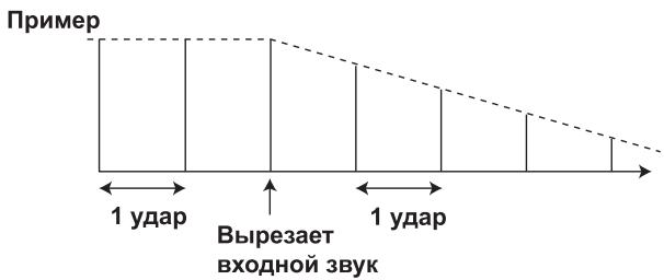
3 Auto TRANS
B eHnHuaX 1/16, 1/8, 1/4, 1/2, 1/1, 2/1, 4/1, 8/1 nIIN 16/1 yIapOB 3bYk aTOMaTHueCKN bIpe3aetc sCHHXPOHHo c pHTMOM.
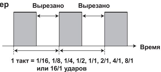
Ppimep
4 FILTER [Фильтр]
3HaunTeJbHoe H3MeHeHHe OKpaCKn 3ByuHaHHIpyTEM CIBHra
aactOtbyΦHJIbTpa B eHNHuaX 1/4, 1/2, 1/1, 2/1, 4/1, 8/1, 16/1, 32/1 HIN 64/1 yapa.
![PIONEER DJM-700-S - FILTER [Фильтр] - 1](/content/2024/12/118750/images/64610ad0ad4ed98e1914db0374ac170c09b854b6c601535af15a1804f626507d.jpg)
Ppimep
5 FLANGER [ɪnɪn]
Побсторе пolyчесни -такторо Ффкета "нзгба" Ддя ударов 1/4, 1/2, 1/1, 2/1, 4/1, 8/1, 16/1, 32/1 Или 64/1.
![PIONEER DJM-700-S - FLANGER [ɪnɪn] - 1](/content/2024/12/118750/images/6190bf889e91b1b1168125995a478ff338ea190988ecbd8f5e8105ab77caecf0.jpg)
Ppimep
6 PHASER [CdBnIgfa3bl]
HactpaHbaET KOJIInueCTBeHHbI IapamTeP BbI6paHHOrO 9ΦΦeKtA.
Iopno6hoe onncahne BInnHnBpaHnpeyJtopa LEVEL/
DEPTH (PARAMETER 2) Ha napametp 2 cm. Ha ctp. 20.
ONEPAUINC PuyhblIM FInIbTPOM
1 PPyHOn ΦnJIbTP
Cdbnraetcaactota hNbtpa, YTO npHBOINT K 6OJIbHIM H3MeHeHHM TOHa.
BpaIeHHepeRyIaToppaIOYacOBoNCTpeJIkeIPOIN3BOIDHTeΦeKTHpA BbICOKHXaCTOT,ABpaIeHHepeRyIaToppaIPOTHBaCobOHNpOIN3BOIDHTeΦeKTHpHbIbTaHH3KHXaCTOT.
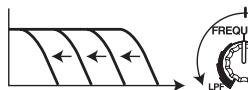
ΦHJbTp Hn3Knx YactOT
Фильт ВьсOKиХ с actOT

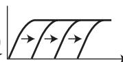
Yactota
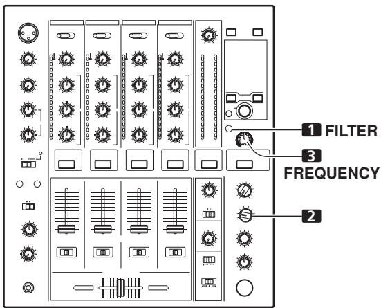
Yactota
PyHOn 3ΦΦeKToP CBzAaC pErpyJIaTOpOM FREQUENCY. BbIXoIHbIe ayINocHrHaJIb C pyHOrO 3ΦΦeKToPa CTaHOBraTcB XoIHbIMn cHrHaJAMn IJI PyTM-3ΦΦeKToB.
- EcJIN TII pHTM-3ΦΦeKTA yCTaHOBJIeH ha ROLL [PiobTOp], REVERSE ROLL [PeBepCnPOBaHHbI IIOBtOp], UP ROLL [PiobTOp cPiobbIeHHem] nDOWN ROLL [PiobTOp cPiOHKeHHem], BbIXOJHOI ayDIOHCnIHajc pHTM-3ΦΦeKToM cTaHOBHcR bXoIHbIM ayDIOHCnIHajOM dJI pyHOrO 3ΦΦeKTopa.
1 Haxmnte KhoNky FILTER, Yo6bI OHa 3AmraJa.
- Y6eIHTecb TOM, YTO KHOIIKa FILTER pOBHOMHraT.
- EcJH OHa TOpHT, HauKMHe KHOIIKy, YTO6bI OHa HauJaMa MHrAtb. KaKdIb pa3 c HauKaTHEm 3ToI KHOIIKn, OHa IpeKeJIIOuHaTec mKdIy peKHMOM MmraHHn H POBHO rOpeHHn.
- IIpn IepBOM BkJIIOUeHIN INITaHnHaCTpOJa IIpeKJIIOuaetcI IO yMOJIuaHnIO Ha pOBHe rOpEnHe.
2 PnIb3yraB nepeKnHouaTeen BbIbopa KaHaJa dna npInIOxHeNHa 3ΦΦeKtA, YTO6bl BbIbpaTb KaHaJI, Ha KOTOpbl 6ydyT DeiCTBOBaTb 3ΦΦeKtBl.
- Ha3BaHHe BbIbpaHHOrO KaHaJa IIOBHTcR Ha IINcIIJee B CeKIIHN MeHH KaHaJa.
EcINBb6paHO [MIC],3ΦΦeKT 6yIeT JeIeCTBOBaTb OJHOBpeMeHHO Ha MHKpOfoH 1 H MHKpOfoH 2.
3ПоьзусberperynatopomFREQUENCY,hactpoTechactoty cpe3aФильтpa.
TEXHINUeCKNE XAPAKTEPNCNIKNI
1 067ne
HapprjkeHne nHTaHn
ot 220 Do 240 B IepeMeHHoTo kA, 50 T/60 T
CtahapThbBxOJHOyPOBeH/BxOJHOHMpeJaHC
BxoI PHONO 2-4 .52 IbB/47 KOM
BxoI MIC 1, MIC 2 .52 IbB/22 KOM
BxoJb LINE, LINE/CD 1-4 .12 JB/22 KOM
BxoI RETURN. -12 IbB/47 KOM
CtanhapTbHbBbXIOHOyOpBeHb/HMIIeIaHcHaŋpy3KN/BbIXOHOH
IMIIaHc
BbIXOIMASTER1. +8 1Bb/10KOM/22OMHMeHBIIe
BbIXOⅡMASTER 2. +2 έB/10 KOM/10 OM
BbIXoI REC. .8 10 KOM/10 OM
BbIXoI BOOTH. +2 Bb/10 KOM/22 OM
BbIXoI SEND .+2 bB/1 KOM/1 KOM
BbIXoJ PHONES. +8,5 12 bB/32 KOM/22 OM nIIM MeHbIe
HOMHaJIbHbI BbIXOJHOyPOBeHb/IMpeJaHC HaPyr3KN
BbIXoI MASTER 1. +25 IbB/10 KOM
BbIXoI MASTER 2. +20日 B / 1 0 ~ K O M
BbocKe NaCTOTbI (HI) .26 1D 6 B (Ha cactote 13 KfU)
CpeHHe qactotbI (MID) ... ot-26 nb do +6 nb (haactote 1 KtU)
Hn3KHe YacToTbI (LOW). . . . . . . . . . . . . . . . . . . . . . . . . . . . . . . . . . . . . . . . . . . . . . . . . . . . . . . . . . . . . . . . . . . . . . . . . . . . . . . . . . . . 6 26 10 70 10 70
BbocKe NaCTOTbI (HI)...0T-12 b+12 b (Ha cactote 10 K)
Hn3KHe YacToTbI (LOW). .ot-12 nB do+12 nB (Ha YacToTe 100 T)
3 BxOaBb/BbxOaBb
BxOJ PHONO
Pa3beMbI RCA. 3
BxoCD
Pa3beMbRCA. 2
BxoI LINE
Pa3beMbI RCA. 3
BxoI MIC
Pa3bEm XLR
Pa3bEm Phone (IHaMaTePOM 6,3 MM) 1
BxoRETURN
BbIXoI REC (ha 3aIIncb)
Pa3beMbI RCA. 1
BbIXoI SEND
H3Дано Pioneer Corporation.
3a\Pi\Pi Ho aBtopcknM IpaBOM © 2007 Pioneer Corporation.
Bce npaba coxpaHebl.
BLOCK DIAGRAM / SCHEMA DE PRINCipe / BLOCKSCHALTBILD / DIAGRAMMA A BLOCCHI / BLOKSCHEMA / DIAGRAMA EN BLOQUES / БLOK-CXEMA ПУЛьТА
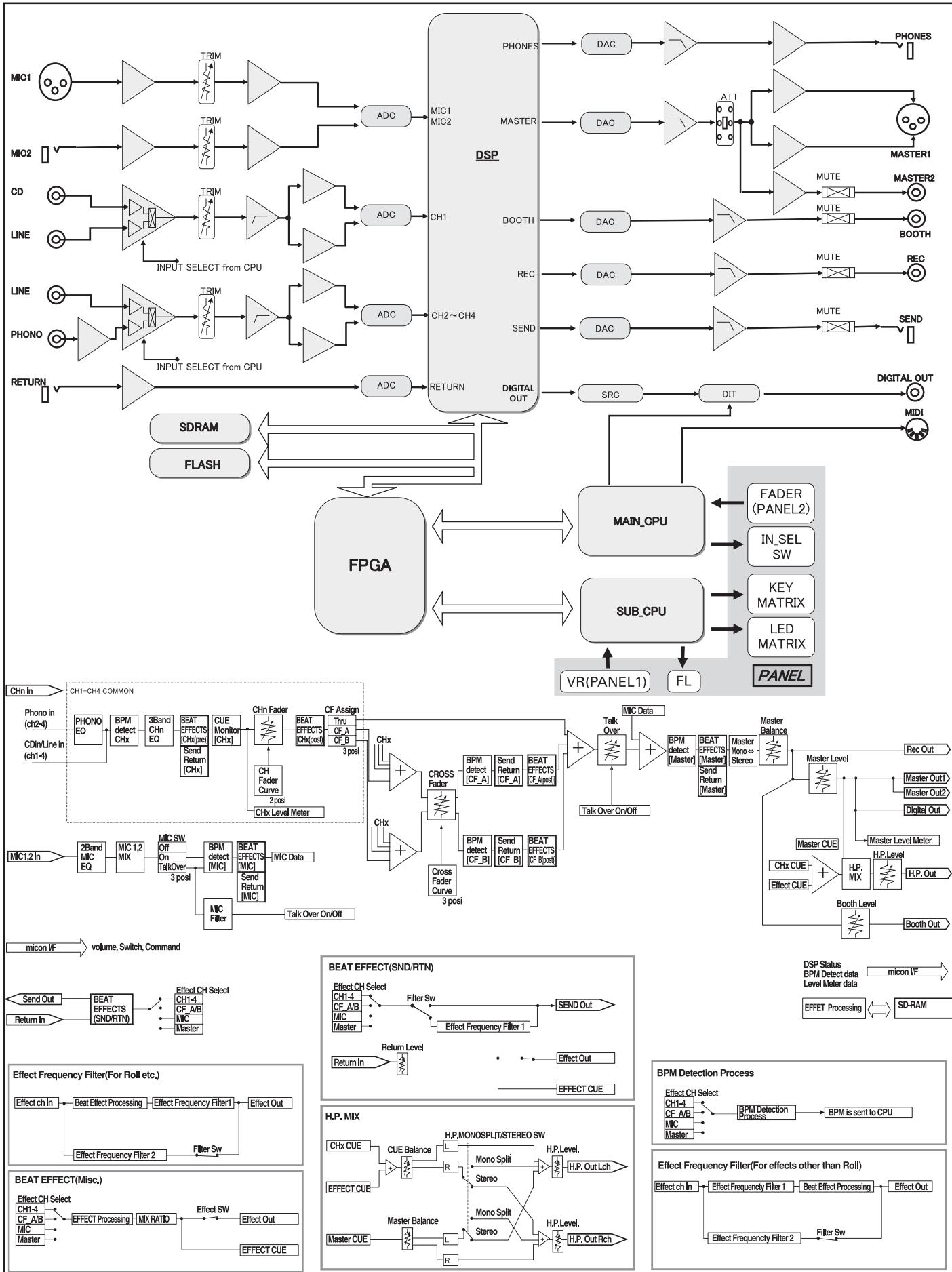
Приимейанne:
B COOTBETCTBmN CO CTaTbei 5 3aKoHa Pocsncko Φeepaun "O 3aUnte npab nortpe6nteJn Yka3aHne IpaBnTeJIbCTBa Pocsncko Φeepaun N2 720 ot 16 nHOy 1997 roJa KOpnpaun Pioneer Europe NV ycTaHaBnBaet ycNoBne Ha cJeDyUOyU npOdoJXnTeIbHocTb cPoka Cnyx6bl OphiuaNbHO NOCTABJMaEh X Ha Pocsnckn pbIHOK TOBapOB.
Aydno n BnDeoo6OpyuObaHne: 7 let
Ipehenochoe ayduoobopyoBaHne: 6 jeT
Published by Pioneer Corporation.
Copyright © 2007 Pioneer Corporation.
All rights reserved.