USER MANUAL DJM-5000 PIONEER
The Pioneer website listed above provides answers to frequently asked questions, information about software, and other up-to-date data of assistance to our customers.
http://www.prodjnet.com/support/
Operating Instructions
Mode d'emploi
Bedienungsanleitung
Thank you for buying this Pioneer product. Please read through these operating instructions so you will know how to operate your model properly. After you have finished reading the instructions, put them away in a safe place for future reference. In some countries or regions, the shape of the power plug and power outlet may sometimes differ from that shown in the explanatory drawings. However the method of connecting and operating the unit is the same.
IMPORTANT

The lightning flash with arrowhead symbol, within an equilateral triangle, is intended to alert the user to the presence of uninsulated "dangerous voltage" within the product's enclosure that may be of sufficient magnitude to constitute a risk of electric shock to persons.
CAUTION
RISK OF ELECTRIC SHOCK DO NOT OPEN
CAUTION:
TO PREVENT THE RISK OF ELECTRIC SHOCK,DO NOT REMOVE COVER (OR BACK).NO USER-SERVICEABLE PARTS INSIDE.REFER SERVICING TO QUALIFIED SERVICE PERSONNEL.

The exclamation point within an equilateral triangle is intended to alert the user to the presence of important operating and maintenance (servicing) instructions in the literature accompanying the appliance.
D3-4-2-1-1 A1 En
Replacement and mounting of an AC plug on the power supply cord of this unit should be performed only by qualified service personnel.
IMPORTANT: THE MOULDED PLUG
This appliance is supplied with a moulded three pin mains plug for your safety and convenience. A 5 amp fuse is fitted in this plug. Should the fuse need to be replaced, please ensure that the replacement fuse has a rating of 5 amps and that it is approved by ASTA or BSI to BS1362.
Check for the ASTA mark or the BSI mark on the body of the fuse.
If the plug contains a removable fuse cover, you must ensure that it is refitted when the fuse is replaced. If you lose the fuse cover the plug must not be used until a replacement cover is obtained. A replacement fuse cover can be obtained from your local dealer.
If the fitted moulded plug is unsuitable for your socket outlet, then the fuse shall be removed and the plug cut off and disposed of safely. There is a danger of severe electrical shock if the cut off plug is inserted into any 13 amp socket.
If a new plug is to be fitted, please observe the wiring code as shown below. If in any doubt, please consult a qualified electrician.
IMPORTANT: The wires in this mains lead are coloured in accordance with the following code: Blue : Neutral Brown : Live
As the colours of the wires in the mains lead of this appliance may not correspond with the coloured markings identifying the terminals in your plug, proceed as follows;
The wire which is coloured BLUE must be connected to the terminal which is marked with the letter N or coloured BLACK.
The wire which is coloured BROWN must be connected to the terminal which is marked with the letter L or coloured RED.
How to replace the fuse: Open the fuse compartment with a screwdriver and replace the fuse.
D3-4-2-1-2-B_En

If you want to dispose this product, do not mix it with general household waste. There is a separate collection system for used electronic products in accordance with legislation that requires proper treatment, recovery and recycling.
Private households in the member states of the EU, in Switzerland and Norway may return their used electronic products free of charge to designated collection facilities or to a retailer (if you purchase a similar new one).
For countries not mentioned above, please contact your local authorities for the correct method of disposal.
By doing so you will ensure that your disposed product undergoes the necessary treatment, recovery and recycling and thus prevent potential negative effects on the environment and human health.
K058b_A1_En
WARNING
This equipment is not waterproof. To prevent a fire or shock hazard, do not place any container filled with liquid near this equipment (such as a vase or flower pot) or expose it to dripping, splashing, rain or moisture. D3-4-2-1-3_B_En
WARNING
Before plugging in for the first time, read the following section carefully.
The voltage of the available power supply differs according to country or region. Be sure that the power supply voltage of the area where this unit will be used meets the required voltage (e.g., 230V or 120V) written on the rear panel. D3-4-2-1-4_A_En
WARNING
To prevent a fire hazard, do not place any naked flame sources (such as a lighted candle) on the equipment. D3-4-2-1-7a_A_En
VENTILATION CAUTION
When installing this unit, make sure to leave space around the unit for ventilation to improve heat radiation (at least 5 cm at rear, and 3 cm at each side).
WARNING
Slots and openings in the cabinet are provided for ventilation to ensure reliable operation of the product, and to protect it from overheating. To prevent fire hazard, the openings should never be blocked or covered with items (such as newspapers, table-cloths, curtains) or by operating the equipment on thick carpet or a bed. D3-4-2-1-7b_A_En
Operating Environment
Operating environment temperature and humidity: +5^ to +35^ (+41^ to +95^) less than 85% RH (cooling vents not blocked)
Do not install this unit in a poorly ventilated area, or in locations exposed to high humidity or direct sunlight (or strong artificial light)
D3-4-2-1-7c*A1_En
If the AC plug of this unit does not match the AC outlet you want to use, the plug must be removed and appropriate one fitted. Replacement and mounting of an AC plug on the power supply cord of this unit should be performed only by qualified service personnel. If connected to an AC outlet, the cut-off plug can cause severe electrical shock. Make sure it is properly disposed of after removal. The equipment should be disconnected by removing the mains plug from the wall socket when left unused for a long period of time (for example, when on vacation).
D3-4-2-2-1a_A1_En
CAUTION
The POWER switch on this unit will not completely shut off all power from the AC outlet. Since the power cord serves as the main disconnect device for the unit, you will need to unplug it from the AC outlet to shut down all power. Therefore, make sure the unit has been installed so that the power cord can be easily unplugged from the AC outlet in case of an accident. To avoid fire hazard, the power cord should also be unplugged from the AC outlet when left unused for a long period of time (for example, when on vacation). D3-4-2-2-2a_A_En
POWER-CORD CAUTION
Handle the power cord by the plug. Do not pull out the plug by tugging the cord and never touch the power cord when your hands are wet as this could cause a short circuit or electric shock. Do not place the unit, a piece of furniture, etc., on the power cord, or pinch the cord. Never make a knot in the cord or tie it with other cords. The power cords should be routed such that they are not likely to be stepped on. A damaged power cord can cause a fire or give you an electrical shock. Check the power cord once in a while. When you find it damaged, ask your nearest PIONEER authorized service center or your dealer for a replacement. 5002*_En
When using this product follow the instructions written on the underside of the unit, which concern rated voltage, etc. D3-4-2-2-4_En
Contents
How to read this manual
The names of displays, menus, and buttons in this manual are enclosed in brackets. (e.g. [Collection] pane, [File] menu, [ / ] )
01 Before start
Features 4
What's in the box. 4
12 Connections
Rear Panel 5
Connecting input terminals 6
Connecting output terminals 6
Connecting to the control panel 7
Connecting a computer. 7
About the USB audio driver software. 7
About USB-MIDI channel setting. 9
03 Operations
Control Panel. 11
Operating the DJ section. 12
Operating the MC section 13
Operating the PA section 14
Troubleshooting 15
About the exemption clauses 15
Block Diagram. 16
Specifications. 17
The screw holes on the left and right of the control panel of this unit match 5U size of any EIA standard 19-inch rack. The maximum depth of this unit is 225.1mm .
- Secure this unit with screws (not supplied) matching the rack.
- Do not install this unit directly above a power amplifier. Heat radiating from the power amplifier may damage this unit. Also, noise (hum noise, etc.) may be generated.
- When transporting this unit, remove it from the rack. Transporting this unit without removing it from the rack may damage this unit.
- If you transport this unit without removing it from the rack, make sure vibration or shock is not applied to this unit.
Before start
Features
The DJM-5000 is a high quality, high performance mixer designed for high sound quality and equipped with many functions offering powerful support for three roles: MC, DJ and PA.
High sound quality processing with 96 kHz sampling, 24-bit high quality A/D converter and 32-bit DSP achieves powerful, high grade sound.
A user-friendly panel layout arranging the three roles (MC, DJ and PA) in separate sections for makes for intuitive operation of the many functions.
MC Section
Microphone features faithfully realizing a high-quality MC performance (page 13)
- This unit is equipped with 2 exclusive channels for a microphone that can be operated intuitively. As you can control the volume and the 3-band equalizer independently, you can adjust the volume and quality of sound according to the voice of an MC in each channel.
- This unit is also equipped with 4 exclusive types of effects for a microphone (REVERB/ECHO+VERB/OCTAYER/PITCH). It is possible to carry out a variety of performances with a microphone.
- CH1 in the DJ section is also available for a microphone input. You can use up to 3 microphones simultaneously.
The world's first, "Advanced Talkover" feature (page 13)
- This unit is equipped with the "Advanced Talkover" feature that makes the sound from a microphone more listenable by automatically lowering the volume in the frequency range of voice against music. The volume of music is not affected by using a microphone, making it possible for you to continue with an MC performance without hurting the atmosphere of the venue (the music level can be adjusted with the knob on the control panel).
1 As of 8/10/2009, for a DJ mixer, as determined by Pioneer.
DJ Section
A built-in "USB audio interface" that makes it possible to input audio directly from a computer (page 7)
- This unit has a built-in "USB audio interface" that can input audio being played back on a computer to a mixer via USB connection to the computer. This makes it possible for you to realize a DJ performance using a computer without an external sound card.
- You can mix up to 3-channel² audio assigned each CH of DJM-5000 with only one computer.
2 A CD-ROM with a driver software is supplied (compatible with Windows and Mac). You can use the audio interface feature by installing the driver software in your computer (For Windows, you can assign 3-channel audio only when an ASIO-compatible software is used).
The "Assignable USB MIDI" feature that can control a MIDI-compatible DJ software (page 9)
- This unit is equipped with the "Assignable USB MIDI" feature that can transmit the operation information of almost all buttons and faders on DJM-5000 to a DJ software in MIDI signals via USB connection to a computer. You can also use it as a MIDI controller with flexible operability.
PA Section
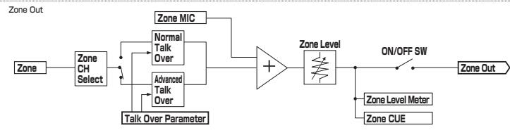
"MASTER/ZONE Split Output" that makes individual performances possible in 2 separate venues with only one device (page 14)
- This unit is equipped with 2-channel output independently assigned to MASTER output and ZONE output. You can output sound in separate channels to 2 venues, realizing a flexible party performance according to the atmosphere of each venue. Likewise, you can output sound from a microphone to a selected destination, realizing an announcement or an MC performance according to the atmosphere of each venue.
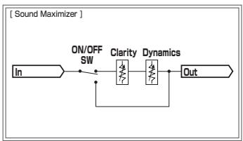
"Sound MAXIMIZER" that can realize the sound setting optimized for specific conditions or atmospheres (page 14)
- This unit is equipped with the "DYNAMICS" and "CLARITY" knobs used to adjust the sound quality. You can generate a deep bass sound in the low-frequency range and a crispy clear sound in the mid- and high-frequency range, which has never been possible with an equalizer. As you can easily adjust the sound quality in the low- and high-frequency range, you can realize an optimum sound setting according to the progress of a party. Also for a compressed sound format like MP3, the sound lost in the low- and high-frequency range is reinforced.
What's in the box
USB Cable
CD-ROM
Warranty card
- Operating instructions (this document)
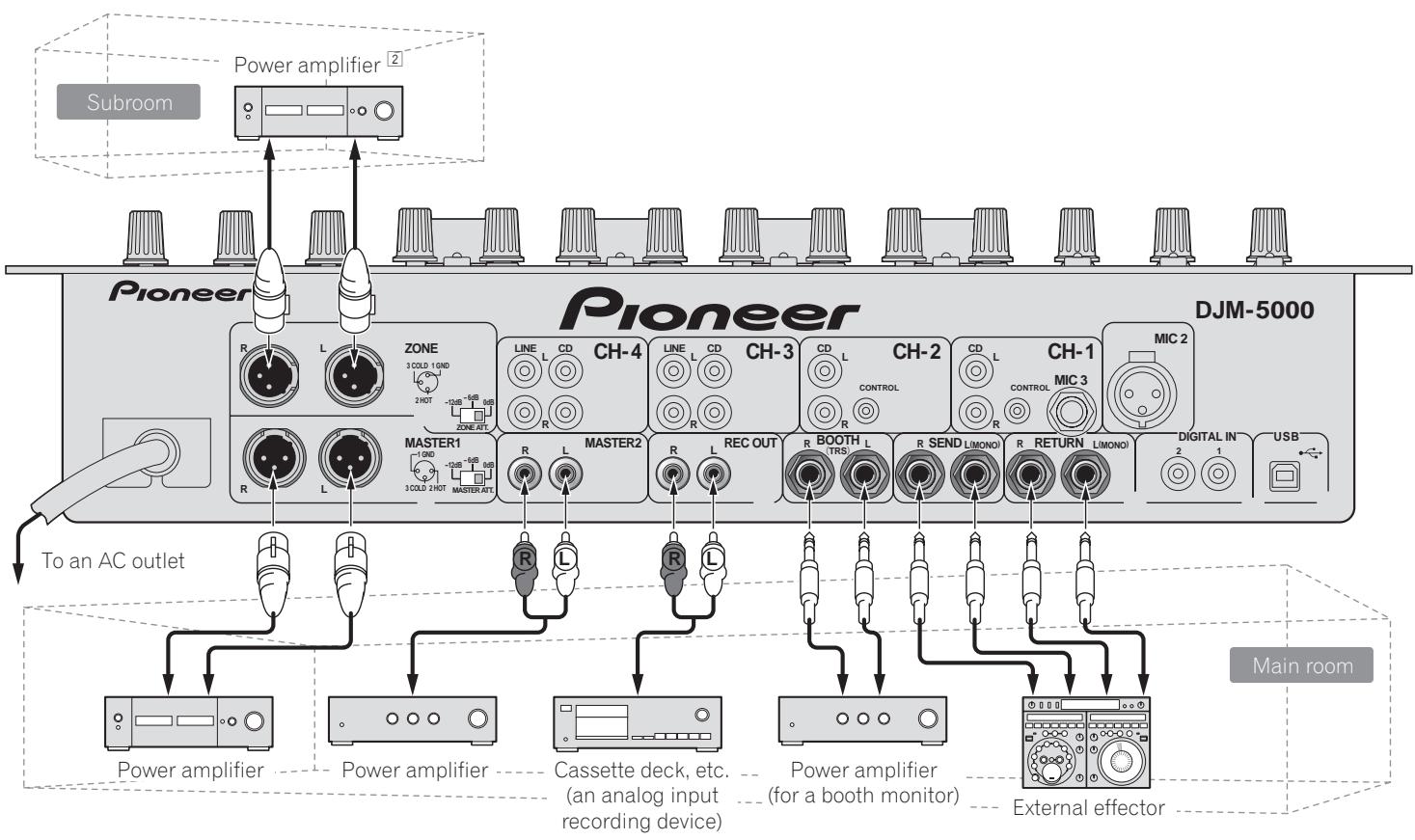
Connections
Be sure to turn off the power and unplug the power cord from the power outlet whenever making or changing connections.
Refer to the operating instructions for the component to be connected.
Connect the power cord after all the connections between devices have been completed.
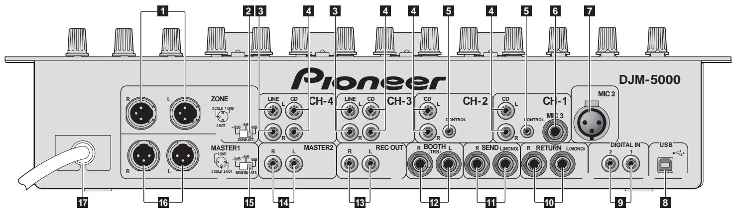
Rear Panel
1 ZONE (page 6)
An output terminal for the ZONE channel.
2 ZONE ATT
Use to switch the attenuation level of audio signals output at the [ZONE] terminal. Select from 0 dB, -6 dB and -12 dB.
3 LINE (page 6)
Connect to a cassette deck or a line level output component.
4 CD (page 6)
Connect to a DJ player or a line level output component.
5 CONTROL (page 6)
This is a control terminal for a DJ player. Use the fader of this unit to control a DJ player.
MIC3 (page 6)
Connect to a microphone.
MIC2 (page 6)
Connect to a microphone.
USB (page 7)
Connect to a computer.
9 DIGITAL IN (page 6)
Connect to a digital audio output component.
RETURN (page 6)
- Connect to the output terminal of an external effector. When the [L] channel only is connected, the [L] channel input is simultaneously input to the [R] channel.
11 SEND (page 6)
- Connect to the input terminal of an external effector. When the [L] channel only is connected, a monaural audio signal is output.
2 BOOTH (page 6)
Output terminals for a booth monitor, compatible with balanced or unbalanced output for a TRS connector.
13 REC OUT (page 6)
This is an output terminal for recording.
14 MASTER2 (page 6)
Connect to a power amplifier, etc.
15 MASTER ATT
Use to switch the attenuation level of audio signals output at the [MASTER1] or [MASTER2] terminal. Select from 0 dB, -6 dB and -12 dB.
16 MASTER1 (page 6)
Connect to a power amplifier, etc.
17 Power cable
Connect to an AC outlet. Plug in the power cord after all connections have been made.
Connecting input terminals
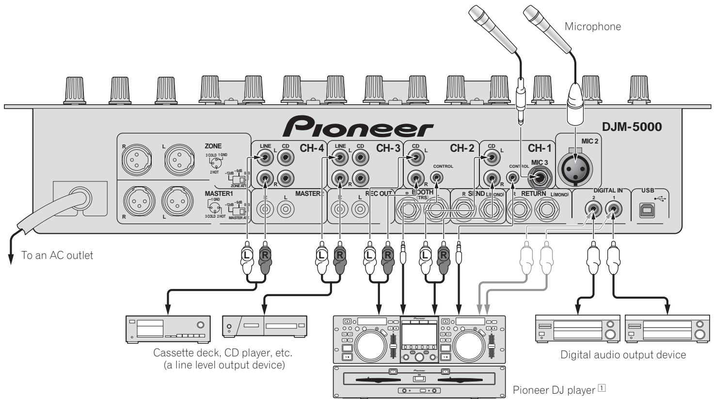
1 Connect a control cable to use the fader start feature (page 12).
Connecting output terminals
2 A sound is output separately from the one in the master channel (MASTER/ZONE split-out).
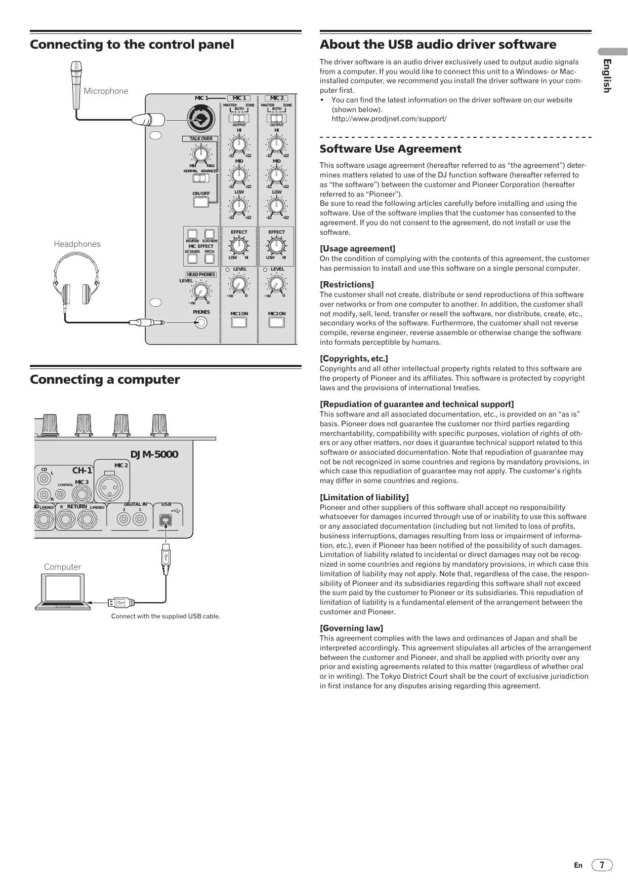
Connecting to the control panel
Connecting a computer
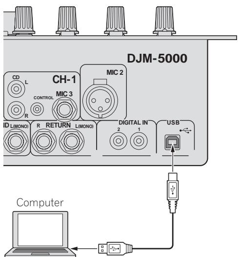
Connect with the supplied USB cable.
About the USB audio driver software
The driver software is an audio driver exclusively used to output audio signals from a computer. If you would like to connect this unit to a Windows- or Mac-installed computer, we recommend you install the driver software in your computer first.
- You can find the latest information on the driver software on our website (shown below).
http://www.prodjnet.com/support/
Software Use Agreement
This software usage agreement (hereafter referred to as "the agreement") determines matters related to use of the DJ function software (hereafter referred to as "the software") between the customer and Pioneer Corporation (hereafter referred to as "Pioneer").
Be sure to read the following articles carefully before installing and using the software. Use of the software implies that the customer has consented to the agreement. If you do not consent to the agreement, do not install or use the software.
[Usage agreement]
On the condition of complying with the contents of this agreement, the customer has permission to install and use this software on a single personal computer.
[Restrictions]
The customer shall not create, distribute or send reproductions of this software over networks or from one computer to another. In addition, the customer shall not modify, sell, lend, transfer or resell the software, nor distribute, create, etc., secondary works of the software. Furthermore, the customer shall not reverse compile, reverse engineer, reverse assemble or otherwise change the software into formats perceptible by humans.
[Copyrights, etc.]
Copyrights and all other intellectual property rights related to this software are the property of Pioneer and its affiliates. This software is protected by copyright laws and the provisions of international treaties.
[Repudiation of guarantee and technical support]
This software and all associated documentation, etc., is provided on an "as is" basis. Pioneer does not guarantee the customer nor third parties regarding merchantability, compatibility with specific purposes, violation of rights of others or any other matters, nor does it guarantee technical support related to this software or associated documentation. Note that repudiation of guarantee may not be not recognized in some countries and regions by mandatory provisions, in which case this repudiation of guarantee may not apply. The customer's rights may differ in some countries and regions.
[Limitation of liability]
Pioneer and other suppliers of this software shall accept no responsibility whatsoever for damages incurred through use of or inability to use this software or any associated documentation (including but not limited to loss of profits, business interruptions, damages resulting from loss or impairment of information, etc.), even if Pioneer has been notified of the possibility of such damages. Limitation of liability related to incidental or direct damages may not be recognized in some countries and regions by mandatory provisions, in which case this limitation of liability may not apply. Note that, regardless of the case, the responsibility of Pioneer and its subsidiaries regarding this software shall not exceed the sum paid by the customer to Pioneer or its subsidiaries. This repudiation of limitation of liability is a fundamental element of the arrangement between the customer and Pioneer.
[Governing law]
This agreement complies with the laws and ordinances of Japan and shall be interpreted accordingly. This agreement stipulates all articles of the arrangement between the customer and Pioneer, and shall be applied with priority over any prior and existing agreements related to this matter (regardless of whether oral or in writing). The Tokyo District Court shall be the court of exclusive jurisdiction in first instance for any disputes arising regarding this agreement.
Cautions on Installation
- Before installing the driver software, be sure to turn off the power of this unit and disconnect the USB cable from both this unit and your computer.
- If you connect this unit to your computer without installing the driver software first, an error may occur on your computer depending on the system environment.
- If you have discontinued the installation process in progress, step through the installation process again from the beginning according to the following procedure.
- Carefully read the provisions of the Software Use Agreement before installing the driver software for exclusive use with this unit.
- Before installing the driver software, terminate all other programs running on your computer.
- The driver software is compatible with the following OSs.
Mac OS X (10.3.9 and later)
Windows Vista® Home Basic/HomePremium/Ultimate/Business
Windows® XP Home Edition/Professional (SP2 or later)
The driver software is not compatible with 64-bit OS (Windows® XP Professional x64 edition and Windows Vista® 64-bit).
- The CD-ROM with the driver software includes an installer running in the following 12 languages.
English, French, German, Italian, Dutch, Spanish, Portuguese, Russian,
Simplified Chinese, Traditional Chinese, Korean, and Japanese
If the language of your OS is one other than the ones listed above, select
[English] following the instructions on the screen.
Installing the driver software
Installation Procedure (Windows)
Carefully read "Cautions on Installation" before installing the driver software.
- To install or uninstall the driver software, you need to be authorized by the administrator of your computer. Log in as the administrator of your computer before proceeding with the installation.
1 Insert the supplied CD-ROM into the CD drive of your computer
The CD-ROM folder appears.
- If the CD-ROM folder is not displayed after a CD-ROM is loaded, open the CD drive from [Computer (or My Computer)] in the [START] menu.
2 Double-click [DJM-5000_X.XXX.exe]
The driver installation screen appears.
3 When the language selection screen appears, select [English] and click [OK]
You can select one from multiple languages depending on the system environment of your computer.
4 Carefully read the Software Use Agreement and if you consent to the provisions, put a check mark in [I agree.] and click [OK]
If you do not consent to the provisions of the Software Use Agreement, click [Cancel] and stop installation.
5 Proceed with installation according to the instructions on the screen
If [Windows Security] appears on the screen while the installation is in progress, click [Install this driver software anyway] and continue with the installation.
- When installing on Windows XP
If [Hardware Installation] appears on the screen while the installation is in progress, click [Continue Anyway] and continue with the installation.
- When the installation program is completed, a completion message appears.
- When the installation of the driver software is completed, you need to reboot your computer.
Installation Procedure (Macintosh)
Carefully read "Cautions on Installation" before installing the driver software.
- To install or uninstall the driver software, you need to be authorized by the administrator of your computer. Have the name and password of the administrator of your computer ready in advance.
1 Insert the supplied CD-ROM into the CD drive of your computer
The CD-ROM folder appears.
- Double-click the CD icon on the desktop when folders are not displayed after a CD-ROM has been loaded.
2 Double-click [DJM-5000_M_X.X.X.dmg]
The [DJM-5000AudioDriver] menu screen appears.
3 Double-click [DJM-5000AudioDriver pkg]
The driver installation screen appears.
4 Check the details on the screen and click [Continue Anyway]
5 When the Software Use Agreement screen appears, select [English], carefully read the Software Use Agreement and click [Continue Anyway]
You can select one from multiple languages depending on the system environment of your computer.
6 If you consent to the provisions of the Software End User License Agreement, click [Agree]
If you do not consent to the provisions of the Software Use Agreement, click [I disagree] and stop installation.
7 Proceed with installation according to the instructions on the screen
- To stop installation in progress, click [Cancel].
- When the installation of the driver software is completed, you need to reboot your computer.
Connecting the DJM-5000 and computer
1 Connect this unit to your computer via a USB cable
This unit functions as an audio device conforming to the ASIO standards.
- When using applications supporting ASIO, [USB 1/2], [USB 3/4] and [USB 5/6] can be used as inputs.
- When using applications supporting DirectX, only [USB 5/6] can be used as the input.
- The computer's recommended operating environment depends on the DJ application. Be sure to check the recommended operating environment for the DJ application you are using.
2 Press [POWER]
Turn on the power of this unit.
- The message [Installing device driver software] may appear when the DJM-5000 is connected to the computer for the first time or when it is reconnected to the computer's USB port. Wait until the [Your devices are ready for use] message appears.
-
When installing on Windows XP
-
[Can Windows connect to Windows Update to search for software?] may appear while the installation is in progress. Select [No, not this time] and click [Next] to continue with the installation.
- [What do you want the wizard to do?] may appear while the installation is in progress. Select [Install the software automatically (Recommended)] and click [Next] to continue with the installation.
- If [Windows Security] appears on the screen while the installation is in progress, click [Install this driver software anyway] and continue with the installation.
Adjusting the buffer size (Windows)
Use this procedure to adjust the computer's buffer size when using an ASIO audio driver.
A sufficiently large buffer size decreases the chance of sound dropout (sound interruption) but increases audio signal transmission delay (latency).
- When an application program (DJ software, etc.) with this unit set as a fixed device is running, terminate the program before adjusting the buffer size.
Checking the version of the driver software
Procedure for checking (Windows)
Click Windows [START] menu >[View All Programs]>[Pioneer]>[DJM-5000]>[DJM-5000 Version Display Utility]
The [Version] screen appears.
Procedure for checking (Macintosh)
Click [Apple] > [About This Mac] > [More Info] > [Extensions] > [DJM-5000 USBAudio]
The [Version] screen appears.
For the latest information on the driver software for exclusive use with this unit, visit our website shown below. http://www.prodjnet.com/support/
About USB-MIDI channel setting
Turn off the power of this unit in advance.
1 Set [MIDI] to [ON]
2 Press and hold [FADER START] for [CH-1] and [CH-2] simultaneously and press [POWER]
When the MASTER [CUE] and ZONE [CUE] buttons light orange, the MIDI channel setting mode is set. Press and hold in [FADER START] for [CH-1] and [CH-2] until the buttons light orange.
- The current MIDI channel setting is displayed in the master level indicator. [L] shows the position of 10, while [R] the position of 1.
The MIDI channel is initially set to [1].
![PIONEER DJM-5000 - Press and hold [FADER START] for [CH-1] and [CH-2] simultaneously and press [POWER] - 1](/content/2020/05/118747/images/b5d6f4ece52d08c5d46f0381a984c118332acbd5b5b6dffe98b1b62c34fe30a0.jpg)
3 Press [CUE] in the [MASTER] channel
The MIDI channel changes by one channel each time you press it. Select a MIDI channel to change the setting.
4 Press and hold [CUE] for the [ZONE] channel
Save the changes made for the MIDI channel.
While settings are being saved, [ON/OFF] flashes for the [SOUND MAXIMIZER] channel. Lights up when the saving is completed.
- Do not turn off the power while saving MIDI channel settings.
5 Press [POWER]
Turn off the power of this unit.
6 Press [POWER]
Turn on the power of this unit again.
Start in the normal mode. The MIDI channel setting is changed.
List of MIDI Messages
| Category | SW Name | SW Type | MIDI Messages | Notes |
| MSB |
| CH-1 | HI | VR | Bn | 2 | dd | 0-127 |
| MID | VR | Bn | 3 | dd | 0-127 |
| LOW | VR | Bn | 4 | dd | 0-127 |
| FADER START | BTN | Bn | 58 | dd | OFF=0, ON=127 |
| CUE | BTN | Bn | 46 | dd | OFF=0, ON=127 |
| Channel fader | VR | Bn | 11 | dd | 0-127 |
| Crossfader Assign Switch | SW | Bn | 41 | dd | A=0, THRU=64, B=127 |
| CH-2 | HI | VR | Bn | 7 | dd | 0-127 |
| MID | VR | Bn | 8 | dd | 0-127 |
| LOW | VR | Bn | 9 | dd | 0-127 |
| FADER START | BTN | Bn | 59 | dd | OFF=0, ON=127 |
| CUE | BTN | Bn | 47 | dd | OFF=0, ON=127 |
| Channel fader | VR | Bn | 12 | dd | 0-127 |
| Crossfader Assign Switch | SW | Bn | 42 | dd | A=0, THRU=64, B=127 |
| CH-3 | HI | VR | Bn | OE | dd | 0-127 |
| MID | VR | Bn | OF | dd | 0-127 |
| LOW | VR | Bn | 15 | dd | 0-127 |
| CUE | BTN | Bn | 48 | dd | OFF=0, ON=127 |
| Channel fader | VR | Bn | 13 | dd | 0-127 |
| Crossfader Assign Switch | SW | Bn | 43 | dd | A=0, THRU=64, B=127 |
| CH-4 | HI | VR | Bn | 51 | dd | 0-127 |
| MID | VR | Bn | 5C | dd | 0-127 |
| LOW | VR | Bn | 52 | dd | 0-127 |
| CUE | BTN | Bn | 49 | dd | OFF=0, ON=127 |
| Channel fader | VR | Bn | 14 | dd | 0-127 |
| Crossfader Assign Switch | SW | Bn | 44 | dd | A=0, THRU=64, B=127 |
| CROSS FADER | Crossfader | VR | Bn | OB | dd | 0-127 |
| CROSS FADER | SW | Bn | 5F | dd | Left=0, Middle=64, Right=127 |
| MASTER | LEVEL | VR | Bn | 18 | dd | 0-127 |
| CUE | BTN | Bn | 4A | dd | OFF=0, ON=127 |
| BALANCE | VR | Bn | 17 | dd | 0-127 |
| MONO/STEREO | SW | Bn | 60 | dd | MONO=0, STEREO=127 |
| BOOTH MONITOR | VR | Bn | 19 | dd | 0-127 |
| ZONE | LEVEL | VR | Bn | 61 | dd | 0-127 |
| CUE | BTN | Bn | 62 | dd | OFF=0, ON=127 |
| ZONE ASSIGN CH-1 | SW | Bn | 20 | dd | 127 |
| ZONE ASSIGN CH-2 | SW | Bn | 21 | dd | 127 |
| ZONE ASSIGN CH-3 | SW | Bn | 22 | dd | 127 |
| ZONE ASSIGN CH-4 | SW | Bn | 23 | dd | 127 |
| ZONE ASSIGN MASTER | SW | Bn | 24 | dd | 127 |
| ZONE ASSIGN OFF | SW | Bn | 25 | dd | 127 |
| ON/OFF | BTN | Bn | 63 | dd | OFF=0, ON=127 |
| SOUND MAXIMIZER | CLARITY | VR | Bn | 64 | dd | 0-127 |
| DYNAMICS | VR | Bn | 65 | dd | 0-127 |
| ON/OFF | BTN | Bn | 4E | dd | OFF=0, ON=127 |
| Category | SW Name | SW Type | MIDI Messages | Notes |
| MSB |
| SEND/RETURN | SEND/RETURN CH-1 | SW | Bn | 30 | dd | 127 |
| SEND/RETURN CH-2 | SW | Bn | 31 | dd | 127 |
| SEND/RETURN CH-3 | SW | Bn | 32 | dd | 127 |
| SEND/RETURN CH-4 | SW | Bn | 33 | dd | 127 |
| SEND/RETURN MIC 1 | SW | Bn | 34 | dd | 127 |
| SEND/RETURN MIC 2 | SW | Bn | 35 | dd | 127 |
| SEND/RETURN MIC 1+2 | SW | Bn | 36 | dd | 127 |
| SEND/RETURN MASTER | SW | Bn | 37 | dd | 127 |
| LEVEL | VR | Bn | 66 | dd | 0-127 |
| ON/OFF | VR | Bn | 40 | dd | OFF=0, ON=127 |
| TALK OVER | LEVEL | VR | Bn | 67 | dd | 0-127 |
| NORMAL/ ADVANCED | SW | Bn | 68 | dd | NORMAL=0, ADVANCED=127 |
| ON/OFF | BTN | Bn | 69 | dd | OFF=0, ON=127 |
| MIC EFFECT | REVERB | BTN | Bn | 6A | dd | OFF=0, ON=127 |
| ECHO+VERB | BTN | Bn | 6B | dd | OFF=0, ON=127 |
| OCTAYER | BTN | Bn | 6C | dd | OFF=0, ON=127 |
| PITCH | BTN | Bn | 6D | dd | OFF=0, ON=127 |
| HEAD PHONES | LEVEL | VR | Bn | 1A | dd | 0-127 |
| MIC 1 | HI | VR | Bn | 1E | dd | 0-127 |
| MID | VR | Bn | 6E | dd | 0-127 |
| LOW | VR | Bn | 1F | dd | 0-127 |
| EFFECT | VR | Bn | 70 | dd | 0-127 |
| MIC1 ON | BTN | Bn | 71 | dd | OFF=0, ON=127 |
| MIC 2 | HI | VR | Bn | 72 | dd | 0-127 |
| MID | VR | Bn | 73 | dd | 0-127 |
| LOW | VR | Bn | 74 | dd | 0-127 |
| EFFECT | VR | Bn | 75 | dd | 0-127 |
| MIC2 ON | BTN | Bn | 76 | dd | OFF=0, ON=127 |
- MIDI ON/OFF controls whether to transmit MIDI messages.
- "n" in the MIDI message "Bn" is a value of the MIDI channel set by the user, ranging from 0x00 to 0xF (1 to 16 on the setting screen)
Control Panel
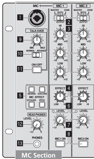
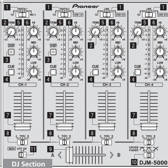
MC Section
MIC1 MIC2
MIC 1 (page 13)
2 OUTPUT (page 13)
3 HI, MID, LOW (page 13)
4 EFFECT (page 13)
5 MIC EFFECT (page 13)
6 Peak Level Indicator (page 13)
LEVEL (page 13)
MIC1 ON, MIC2 ON (page 13)
TALKOVER
9 Talk-Over Level (page 13)
10 NORMAL/ADVANCED (page 13)
11 ON/OFF (page 13)
HEAD PHONES
LEVEL (page 12)
13 PHONES (page 12)
DJ Section
CH-1 CH-4
Input Selector Switch (page 12)
TRIM (page 12)
3 FADER START (page 12)
4 CUE (page 12)
5 Channel Level Indicator (page 12)
HI, MID, LOW (page 12)
7 Channel Fader (page 12)
CROSS FADER
3 Crossfader Assign Switch (page 12)
9 Crossfader (page 12)
10 [CROSS FADER] (Crossfader Curve Selector Switch) (page 12)
MIDI
MIDI (page 12)
PA Section
MASTER
LEVEL (page 12)
2 Master Level Indicator (page 12) Displays the level of audio signals that have passed through [LEVEL] in the [MASTER] channel.
3 CUE (page 12)
4 BALANCE (page 14)
5 MONO/STEREO (page 14)
6 BOOTH MONITOR (page 14)
ZONE
LEVEL (page 14)
Zone Level Indicator (page 14) Displays the level of audio signals that have passed through [LEVEL] in the [ZONE] channel.
9 CUE (page 12)
10 Output Channel Selector Switch (page 14)
11 ZONE ON (page 14)
SOUND MAXIMIZER
12 CLARITY (page 14)
18 DYNAMICS (page 14)
14 ON/OFF (page 14)
SEND/RETURN
15 Output Channel Selector Switch (page 14)
LEVEL (page 14)
17 ON/OFF (page 14)
POWER
18 POWER (page 12)
Operating the DJ section
Outputting sound
1 Press [POWER]
Turn on the power of this unit.
Select the input source of each channel from the components connected to this unit.
- To output sound of the computer connected to the [USB] terminal, switch the input selector switch for [CH-2], [CH-3], and [CH-4] to [USB].
3 Rotate [TRIM]
Adjusts the level of audio signals input in each channel.
- The channel level indicator lights when the sound is being properly input to the channel.
4 Set the channel fader to the inner position
Adjusts the level of audio signals output in each channel.
5 Adjust the crossfader assign switch
Switches the output destination of each channel.
- [A]: Assigns to [A] (left) of the crossfader.
- [B]: Assigns to [B] (right) of the crossfader.
- [THRU]: Assigns to the [MASTER] channel (the crossfader is not passed through).
6 Adjust the crossfader curve switch ([CROSS FADER])
Switches the crossfader curve characteristics.
- [7]: Makes a sharply increasing curve (if the crossfader is moved away from the [A] side, audio signals are immediately output from the [B] side).
- [N]: Makes a curve shaped between the two curves above and below.
- [X] : Makes a gradually increasing curve (if the crossfader is moved away from the [A] side, the sound on the [B] side gradually increases, while the sound on the [A] gradually decreases).
7 Set the crossfader
Outputs audio signals assigned by the crossfader assign switch corresponding to the curve characteristics selected by [CROSS FADER] (Crossfader Curve Selector Switch).
- You do not need to follow this step when the crossfader assign switch is set to [THRU].
8 Rotate [LEVEL] for the [MASTER] channel
The sound is output from [MASTER1] and [MASTER2]. The master level indicator lights.
Adjusting the sound quality
Rotate [HI], [MID] or [LOW] in each channel
Refer to Specifications on page 17 for the range of sound that can be adjusted by each control.
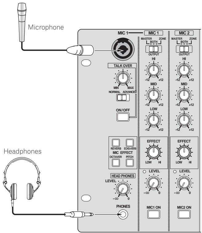
Monitoring sound with headphones
1 Connect headphones to the [PHONES] jack
2 Press [CUE] for the channel to be monitored
The button lights up brightly in orange.
3 Turn the [LEVEL] dial for [HEAD PHONES]
Sound is output from the headphones in the channel selected by [CUE].
Sound output from the headphones varies according to the combination of channels selected by [CUE]. See the table below.
| CH-1 - CH-4 | MASTER | ZONE | Headphone Output |
| L channel | R channel |
| ON | OFF | OFF | CH (L) | CH (R) |
| OFF | ON | OFF | MASTER (L) | MASTER (R) |
| OFF | OFF | ON | ZONE (L) | ZONE (R) |
| ON | ON | OFF | CH (MONO) | MASTER (MONO) |
| ON | OFF | ON | CH (MONO) | ZONE (MONO) |
| OFF | ON | ON | MASTER (L)+ZONE (L) | MASTER (R)+ZONE (R) |
| ON | ON | ON | CH (MONO) | MASTER (MONO)+ZONE (MONO) |
- Monitoring is canceled if you press [CUE] again. The button lights up dimly in orange.
Using the fader to play a Pioneer DJ player (fader start)
If you connect a Pioneer DJ player using a control cable (supplied with a DJ player), you can start playback of control other operations of the DJ player with the fader of this unit.
The fader start feature is available only when a Pioneer DJ player is connected to [CH-1] or [CH-2].
Connect a Pioneer DJ player to this unit in advance (page 6).
Start playback using the channel fader
1 Set the crossfader assign switch to [THRU]
2 Press [FADER START]
Turn on the fader start function. The button lights up brightly in orange.
3 Set the channel fader to the outermost position
4 Set the cue on the DJ player
The DJ player pauses playback at the cue point.
5 Set the channel fader to the inner position
Playback starts on the DJ player.
- If you set the channel fader back to the original position, the player instantaneously returns to the cue point already set and pauses playback (back cue).
Start playback using the crossfader
1 Set the crossfader assign switch to [A] or [B]
2 Press [FADER START]
Turn on the fader start function. The button lights up brightly in orange.
3 Set the crossfader
Set to the farmost end in the opposite direction to the channel to be fader started.
4 Set the cue on the DJ player
The DJ player pauses playback at the cue point.
5 Set the crossfader
Playback starts on the DJ player.
- If you set the crossfader back to the original position, the player instantaneously returns to the cue point already set and pauses playback (back cue).
Operating the DJ software
The DJM-5000 also outputs the operating data for the buttons and dials in MIDI format. If you connect a computer with a built-in MIDI-compatible DJ software via a USB cable, you can operate the DJ software on this unit.
Install the DJ software on your computer in advance. Also, adjust audio and MIDI settings for the DJ software.
1 Connect the USB port on this unit to your computer
For details about connections, see Connecting a computer on page 7.
2 Start the DJ software
3 Set [MIDI] to [ON]
Transmission of the MIDI messages begin.
- You can send MIDI messages altogether according to the position of buttons, faders, or control knobs (snapshot).
- Adjust faders and control knobs to transmit messages based on the corresponding position. For details about the messages generated by this unit, see List of MIDI Messages on page 10.
4 Set [MIDI] to [OFF]
The MIDI messages are not transmitted even if you operate this unit.
Operating the MC section
Using a microphone
1 Switch [OUTPUT]
Select the output destination of the sound output from the [MIC1] or [MIC2] channel.
2 Rotate [LEVEL] for the microphone channel
Adjusts the level of audio signals output from the microphone channel.
- Pay attention that rotating to the extreme right position outputs a very loud sound.
3 Press [MIC1 ON] for the [MIC1] channel or [MIC2 ON] for the [MIC2] channel
Turn on the microphone channel. The button lights up in green.
Sound is output to the output destination selected in step 1.
- The peak level indicator lights in different colors corresponding to the level of audio being input.
Green: Permissible level
Orange: Appropriate level
- Red: Excessive level (lower the level of audio by rotating [LEVEL] to the left)
Adjusting the sound quality
Rotate [HI], [MID] or [LOW] for the [MIC1] or [MIC2] channel
Refer to Specifications on page 17 for the range of sound that can be adjusted by each control.
Using the microphone effect feature
1 Press [MIC EFFECT (REVERB, ECHO+VERB, OCTAYER or PITCH)]
Turn on the microphone effect function. The button flashes in blue.
- The effect varies depending on the button.
2 Rotate [EFFECT]
Adds an effect to the sound output from the microphone channel.
- The effect varies according to the rotation direction and position of [EFFECT].
| Effect Name | Descriptions |
| REVERB1 | Adds a reverberation effect to the original sound. |
| ECHO+VERB1 | Adds reverberation and echo effects to the original sound. |
| OCTAYER1 | Adds sound with 1 octave up and down to the original sound. |
| PITCH | Changes the musical interval within the range of 1 octave up and down. Rotate it to the right and left to change the interval 1 octave up and down respectively. |
1 The more you rotate it to the right, the louder the effect sound.
- When you turn off the microphone effect function, press the flashing [MIC EFFECT (REVERB, ECHO+VERB, OCTAYER, PITCH)] once again. The button lights up in blue.
Using the talk-over feature
1 Rotate the talk-over level
Set the attenuation level of sound besides the one in the microphone channel.
2 Switch between [NORMAL]/[ADVANCED]
The attenuation mode for the talk-over function switches.
Normal talk over:
The sound output from channels other than the microphone channel is attenuated by the amount set for the talk over level.
![PIONEER DJM-5000 - Switch between [NORMAL]/[ADVANCED] - 1](/content/2020/05/118747/images/214c22f756ee3565e8d98b4882bdd2d842a88a61a9e7cf56862957b0f9bd3169.jpg)
Advanced talk over:
Only the voice band of the sound output from channels other than the microphone channel is attenuated by the amount set for the talk over level.
![PIONEER DJM-5000 - Switch between [NORMAL]/[ADVANCED] - 2](/content/2020/05/118747/images/15e0cf8849970e3001e418bde83d7c7a8ce299b7b1398c37b04a1b33ef48d55d.jpg)
3 Press [ON/OFF] for [TALK OVER]
Turn on the talk-over function. The button lights up in red.
- When audio signals are input in the microphone channel, the sound, besides the one in the microphone channel, is attenuated according to the attenuation mode setting and the position of the control.
Operating the PA section
Outputting sound from the ZONE terminal
You can output sound from the [ZONE] terminal besides the sound output from the master channel.
1 Set the output channel selector switch for the [ZONE] channel
Select the channel output from the [ZONE] terminal.
Sound output varies according to the position of the switch.
| Switch Position | 1 | 2 | 3 | 4 | MASTER | MIC |
| Audio Output | CH-1① | CH-2① | CH-3① | CH-4① | Microphone Channel ② | Microphone Channel ③ |
Audio is output regardless of the position of faders and control knobs.
2 Audio is output regardless of the position of [LEVEL] for the [MASTER] channel.
3 Audio is output only from the microphone channel, for which [OUTPUT] is set to [BOTH] or [ZONE].
2 Press [ZONE ON] for the [ZONE] channel
Turn on the [ZONE] channel. The button lights up in green.
3 Rotate [LEVEL] for the [ZONE] channel
Sound is output at the [ZONE] terminal. The zone level indicator lights up.
To turn the [ZONE] channel off, press [ZONE ON] again. The button turns off.
Using the sound maximizer feature
1 Press [ON/OFF] for [SOUND MAXIMIZER]
Turn on the sound maximizer function. The button lights up in blue.
2 Rotate [CLARITY] or [DYNAMICS]
The effect of the sound maximizer varies according to the rotation direction and position of the control.
- The output audio level increases according to the sound maximizer effect when the dial is turned clockwise. Pay attention to the output audio level when using the sound maximizer function.
![PIONEER DJM-5000 - Rotate [CLARITY] or [DYNAMICS] - 1](/content/2020/05/118747/images/2f61d6a75e2f185014166d45bc4d4e41c17836c828fc6be9d1ff60bdea4bda6b.jpg)
The range of sound that can be adjusted varies according to the control.
- CLARITY: Adjusts the attack and outline of sound mainly in the mid and high range (high hat, snare, etc.).
DYNAMICS: Adjusts modulation and rhythm mainly in the low range.
- When you turn off the sound maximizer function, press [ON/OFF] again. The light of the button turns off.
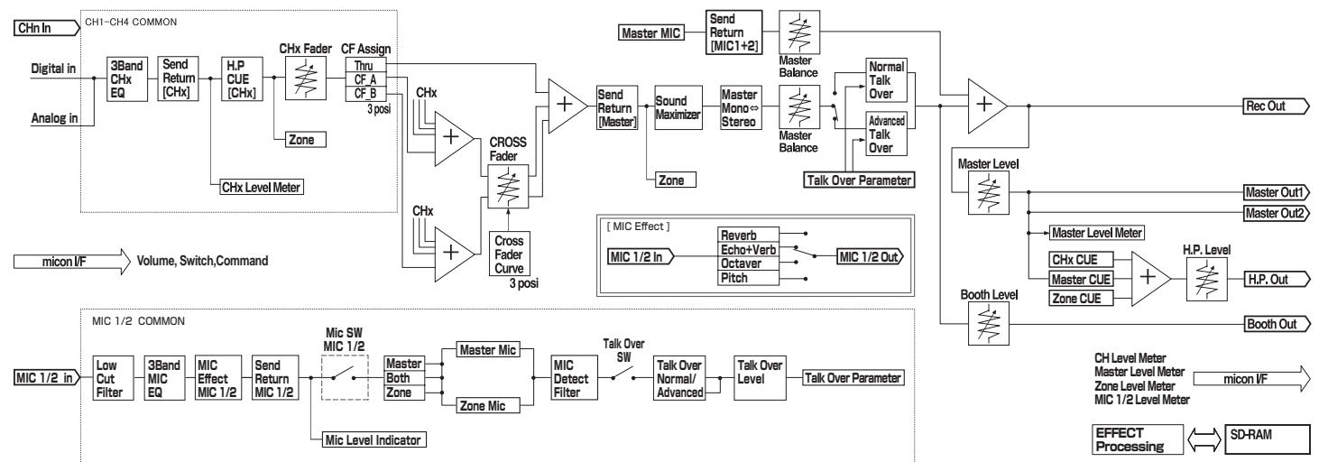
Using the external effector
1 Connect the external effector
[ON/OFF] of [SEND/RETURN] lights up in red. When the external effector is not connected, [ON/OFF] does not light up.
- For details about connections, see Connections on page 5.
2 Set the output channel selector switch for the [SEND/RETURN] channel
Select the channel output from the [SEND] terminal.
Sound output varies according to the position of the switch.
| Switch Position | 1 | 2 | 3 | 4 | MIC 1 | MIC 2 | MIC1+2 | MASTER |
| Audio Output | CH-1 | CH-2 | CH-3 | CH-4 | MIC 1 | MIC 2 | MIC1+2[1] | Master Channel |
The microphone sound output from the master channel is output from the [SEND] channel.
3 Press [ON/OFF] for [SEND/RETURN]
Sound is output at the [SEND] terminal. The button flashes in red.
4 Turn the [LEVEL] dial for [SEND/RETURN]
Adjusts the level of audio signals input at the [RETURN] terminal.
- To stop the sound output at the [SEND] terminal, press the flashing [ON/OFF]. The button lights up.
Switching between monaural and stereo audio
You can switch between monaural and stereo audio for the sound output at the [MASTER1], [MASTER2], [BOOTH], [REC OUT] or [PHONES] terminal.
Switch between [MONO]/[STEREO]
- [MONO]: Outputs monaural audio.
- [STEREO]: Outputs stereo audio.
Adjusting the L/R balance of audio
The left/right balance of the sound output from the [MASTER1], [MASTER2], [BOOTH], [REC OUT] and [PHONES] terminals can be adjusted.
1 Set [MONO]/[STEREO] to [STEREO]
2 Rotate [BALANCE]
The L/R balance of audio varies according to the rotation direction and position of the [BALANCE] control.
- Rotating to the rightmost position outputs only the right sound of stereo audio. Rotating to the leftmost position outputs only the left sound of stereo audio.
Audio is output from the [BOOTH] terminal
The master channel audio, except the microphone channel audio, is output from the [BOOTH] terminal regardless of the position of [LEVEL] in the [MASTER] channel.
Rotate [BOOTH MONITOR]
Adjusts the level of audio signals output at the [BOOTH] terminal.
Troubleshooting
Incorrect operation is often mistaken for trouble or malfunction. If you think that there is something wrong with this component, check the points below. Sometimes the trouble may lie in another component. Inspect the other components and electrical appliances being used. If the trouble cannot be rectified after checking the items below, ask your nearest Pioneer authorized service center or your dealer to carry out repair work.
The player may not operate properly due to static electricity or other external influences. In such cases, normal operation may be restored by unplugging the power cord then plugging it back in.
| Problem | Check | Remedy |
| The power is not turned on. | Is the power cord properly connected? | Plug in the power cord to an AC outlet. |
| No sound or small sound. | Is the position of the input selector switch properly set? | Switch the input source of a channel with the input selector switch (page 11). |
| Are the connection cables properly connected? | Connect the connection cables properly (page 6). |
| Are the terminals and plugs dirty? | Clean the terminals and plugs before making connections. |
| Is [MASTER ATT] on the rear panel set to a level like -12 dB? | Switch [MASTER ATT] (page 5). |
| Distorted sound. | Is the level of audio output from the microphone channel properly set? | Adjust the [LEVEL] dial for [MASTER] so that the master channel level indicator lights at about 0 dB at the peak level (page 11). |
| Set [MASTER ATT] to [-6 dB] or [-12 dB] (page 5). |
| Is the level of audio input to each channel properly set? | Adjust the [TRIM] control such that the channel level indicator lights up near 0 dB at the peak level (page 11). |
| Can't crossfade. | Is the crossfader assign switch properly set? | Set the crossfader assign switch properly for each channel (page 11). |
| Can't fader start a DJ player. | Is [FADER START] set to off? | Set [FADER START] to on (page 12). |
| Is the DJ player properly connected to the [CONTROL] terminal? | Connect a DJ player to the [CONTROL] terminal with a control cord (page 6). |
| Are the audio cables properly connected? | Connect this unit to the audio output terminal of a DJ player with an audio cable (page 6). |
| No effect. | Is [EFFECT] set to a proper position? | Set [EFFECT] to a position other than [LOW] (page 11). |
| Can't use an external effector. | Is [SEND/RETURN] [ON/OFF] set to on? | Press [ON/OFF] of [SEND/RETURN] to turn on [SEND/RETURN] (page 11). |
| Is the external effector properly connected to the [SEND] or [RETURN] terminal? | Connect an external effector to the [SEND] or [RETURN] terminal. When the connection is made properly, [ON/OFF] of [SEND/RETURN] lights up in red (page 6). |
| Is the output channel switch of [SEND/RETURN] properly set? | Switch the output channel with the output channel selector switch(page 11). |
| Distorted sound from an external effector. | Is the level of audio input from the external effector properly set? | Turn the [LEVEL] dial for [SEND/RETURN] to adjust the audio level output from the external effector (page 11). |
| This unit is not recognized after it has been connected to a computer. | Is the driver software properly installed on your computer? | Install the driver software. Reinstall it if the driver software has already been installed (page 7). |
| Unless this unit is properly connected to the computer and there is no error in data transmission, the version display utility program cannot display the firmware of this unit. For details of how to check, see Checking the version of the driver software on page 9. |
About the exemption clauses
- Pioneer is a registered trademark of Pioneer Corporation.
- Microsoft®, Windows Vista®, and Windows® are registered trademarks or trademarks of Microsoft Corporation in the United States and/or other countries.
- Pentium is a registered trademark of Intel Corporation.
Adobe and Reader are either registered trademarks or trademarks of Adobe Systems Incorporated in the United States and/or other countries.
Apple, Macintosh or Mac OS are registered trademarks of Apple Inc. in the United States and/or other countries.
ASIO is a trademark of Steinberg Media Technologies GmbH.
- The names of companies and products mentioned herein are the trademarks of their respective owners.
This product has been licensed for nonprofit use. This product has not been licensed for commercial purposes (for profit-making use), such as broadcasting (terrestrial, satellite, cable or other types of broadcasting), streaming on the Internet, Intranet (a corporate network) or other types of networks or distributing of electronic information (online digital music distribution service). You need to acquire the corresponding licenses for such uses. For details, visit http://www.mp3licensing.com.

Fraunhofer
Institut
The audio compression technology for MP3 is offered under the license of Fraunhofer IIS and Thomson Multimedia.
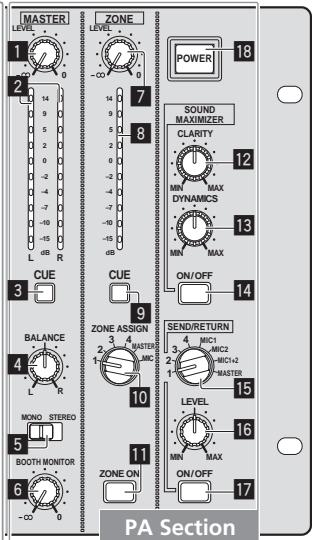
Block Diagram
Specifications
General
Power requirements.. AC 220 V to 240 V, 50 Hz/60 Hz
Power consumption 33 W
Main unit weight 6.9 kg
External dimensions. 482.6 mm (W) x 107.8 mm (H) x 225.1 mm (D)
Tolerable operating temperature. +5^ to +35^
Tolerable operating humidity. 5% to 85% (no condensation)
Audio Section
Sampling rate 96 kHz
A/D, D/A converter. 24 bits
Frequency characteristic
CD/LINE/MIC. 20 Hz to 20 kHz
S/N ratio (rated output)
CD/LINE 102 dB
MIC 84 dB
Total harmonic distortion (LINE - MASTER1) 0.005 %
Standard input level / Input impedance
MIC1, MIC2 -52 dBu/22 kΩ
MIC3 -52 dBu/47 kΩ
CD/LINE (3, 4) -12 dBu/47 kΩ
RETURN. -12 dBu/47 kΩ
Standard output level / Load impedance / Output impedance
MASTER1 +8dBu / 10k /10 or lower
MASTER2 +2dBu / 10k /10 or lower
REC OUT. -8 dBu/10 kΩ/10 Ω or lower
BOOTH +8 dBu/10 kΩ/600 Ω
ZONE. +8dBu / 10k /600 (ATT O dB)
SEND. -12 dBu/10 kΩ/1 kΩ or lower
PHONES. +8.5dBu / 32 /22 or lower
Rated output level / Load impedance
MASTER1 +25dBu / 10k
MASTER2 +20 dBu/10 kΩ
ZONE. +25dBu / 10k (ATT 0 dB)
Crosstalk (LINE) 80 dB
Channel equalizer characteristic
HI. -26 dB to +6 dB (13 kHz)
MID 26 dB to +6 dB (1 kHz)
LOW. -26 dB to +6 dB (70 Hz)
Microphone equalizer characteristic
HI. -12 dB to +12 dB (10 kHz)
MID -12 dB to +12 dB (2.5 kHz)
LOW. -12 dB to +12 dB (100 Hz)
CD input terminal
RCA pin jack 4
LINE input terminal
RCA pin jack 2
MIC input terminal
XLR connector/Phone jack (Ø 6.3 mm) 1
XLR connector 1
Phone jack (0 6.3 mm) 1
RETURN Input terminals
Phone jack (0 6.3 mm) 1
ZONE output terminal
XLR connector. 1
MASTER output terminal
XLR connector 1
RCA pin jack 1
BOOTH output terminal
Phone jack (6.3 mm) 1
REC OUT output terminal
RCA pin jack 1
SEND output terminal
Phone jack (6.3 mm) 1
DIGITAL IN coaxial input terminal
RCA pin jack 2
PHONES output terminal
Stereo phone jack (6.3 mm)
USB terminal
B-type 1
CONTROL terminal
Mini phone jack (0 3.5 mm) 2
- The specifications and design of this product are subject to change without notice.
Published by Pioneer Corporation. Copyright © 2009 Pioneer Corporation. All rights reserved.
II software driver audio USB. 7
II software driver audio USB
Usage: This procedure is used to record the parameters of a driver audio.
1 Premere [MIC EFFECT (REVERB, ECHO+VERB, OCTAYER o PITCH)]
WAARSCHUWING NETSNOER
Controlemethode (Macintosh)
Klik op [Apple]>[Over dele Mac]>[Meer info]>[Extensies]>[DJM-5000 USBAudio]
4 Stel [MIDI] in op [OFF]
De MIDI-berachten worden nicht verzonden, ook al bedient u dit apparaat.
1 Druk op [MIC EFFECT (REVERB, ECHO+VERB, OCTAYER of PITCH)]
1 Stel [MONO]/[STEREO] in op [STEREO]
WindowsXP Home Edition/Professional (SP2 o posterior)
1 Pulse [MIC EFFECT (REVERB, ECHO+VERB, OCTAYER o PITCH)]
1 Ponga [MONO]/[STEREO] en [STEREO]
2 Gire [BALANCE]
CD/LINE/MIC. 20 Hz a 20 kHz
HI. -12 dB a + 12 dB (10 kHz)
MID .-12 dB a + 12 dB (2,5 kHz)
LOW. -12 dB a +12 dB (100 Hz)
Pockolybye zeta npobovc bceTBOE OTOB YCTOPOCTBA MORYT HE COOTBETCBOBATy BOEOM BAPKIOBKE, cNOblyEMOB BAWEI 03eTK, To noctynatye CnDyoUcIM o6A30m:
PpOBoCINHEO zBeta Heo6xOIMn POKnIIOuTa b K YEPHOMY KOHTaKToN NIn KOHTaKTo, KoTOpBn NomeeH 6yKBoN
[HeɪtpaɪbHbɪŋ]
PINOBOD KOPINUHEBOO CUBEta Heo6xIDMO NOKJIHOATb K PACHOMY KOHACTy IINI KOHACTy, NOMEEHNOMy 6yKB0I L [PION HANPAHENHM].
3aMeHa npdoxpanhtela: OtkpoTe OTBepTKoH NHy, B KToTOp oYCTAOHOBnE npdoxpanHTeIb, n 3aMeHnTe PnabKn npdoxpanHTeIb.
IPEDyPENPEXDEHNE
Bo n36exaHne noXapa He np6nkae
OobopydOBaHHIO NCTOCHNKOTKpbItorOOrHn(HaNPmEp,3axxKeHHbIe CBeuN). D3-4-2
EcnnBnBnKaIshypaNITAHNIAH3dEINNA He COOTBETCTbYET NMeIOUeJcA 3NeKTPropo3eTKe, BnIKy CneDyET 3aMeHnTB Ha NOxOJaIyU Ko3eTKe. 3aMeHa U yctAHOBKa BnIKN DOnJIHb IpnON3BoNTbcr ToJIbKO bAIniΦuIcPOBaHHbIM TexHNIOM.
OTcoednHeHHaT O Ka6eN BnIka, POKKIOUeHHaK pO3eTKe, MOKET b3BaTb TReJe0e nopaxHeNe 3eKTPuYeCKM TokOM. PocSe ydaJIeHOM BnIKyTInH3npYIte ee DoJNkHbIM o6pa3OM.
O6OpyOBaHnE CneIeYET OTKNIOUaTb OT aNeKTPocetIn, H3NBeKaeBnIKy Ka6EJI NITaHnIA N3 pOeTKn, eCnI OHO He bEyET IcNIOBtOBAITcBc B TceHe DOrToRBOpeMeHn (HaNPmEp, eCnI BBy eZ3xaeteB eOTnyCK).
D3-4-2-2-1a_A1_Ru
BHIMAHNE
BbIKJIOHateJIb POWER
daHHoro yctpoiCTBa He noHIOCTbIO OTKJIIOVAeT erOOT 3NEKTPOcETn. TQo6bl noHIOCTbIO OTKJIIOVHTB nITAHne yctpoCTBa, BbIaunite BnIKy Ka6EbnI NITAHnI IN3 3NEKTropo3ETKn. PO3OTMy yctpCTBO CNeJyET yCTaHABNIMBat Tak, YTO6bl BNkY Ka6EbnI NITAHnI MOKHO bIbI NOIeKo BbITaunltb IN3 p03ETKn B 4pe3BbUaahbIX o6CToRtEnbCTbax. BO n36EkaHHe NOXapa CNeJyET IN3BNeKATb BNIKY Ka6EbnI NITAHnIN3 p03ETKn, eCIn yCTpoCTBO He 6yBeT JNC0JIb3OBAbTcB B TceHMe DOnrTO BVPemHn (HaNPmEp, eCIn BbI ye3KaAeTe B OTNuCK).
D3-4-2-2-2a_A_Ru
MEpbI IPEIOCTOPOXHOCTN PNI O6PAAUHIN C CETEBbIM UHNYPOM
Дерхит eceBoI shHy 3a BILky. He BbITACKBAIte BILKY, B3A8BUNCb 3a shHyp, n HNKoRda He kacaIeTcB cTeBO rO shHpya, ecn Baan pyKn BlnaxkhIe, TAK KAK 3To MOKeT npINBECTN K KOPOTKOVI 3AMblKaHHIO nII npopaxHENIO 3JIeKTPmECKM TKOM. He CTabBe T annapat, npedMeTb Me6eJIn T.d. Na cTeBOI shHyp, He 3aXkMaIte erO. He 3aBz3bIABaTe y3IOB Ha shHype I Nc CBz3bIABaTe erO C dpyTmN shHypam. CTeBbe IshHypbl DOnJXhbl JExKaTb TaK, YTObSI HA HN HEN bIbI NaHCTyPHTb. IObpexDeHHbI cTeBOI shHyp MOxET cTaB npuHHO Bo3HNKHOBeHn NOXapa IIN nOpa3NTb Bac 3JIeKTPmECKM TKOM. Bpema OT BpemEHn npOBepraIe CTeBOI shHyp. B Cnyae O6hApUxHENIO NpOBpEXdHnio OpbATnTEc 3aMeHOB B 6NIkXaiWn OphiuaJIbHbI cepBNCbI CEHTP PhmBI PIONEER INIK BAWeMy DNJIepy.
S002*_Ru
Copepkanne
Kak cIeJyET uHTaTb daHHe pkykoBcTBO
Ha3BaHnIg 3KpaHOB, MeHIO N KHOtOK B DaHHOM pyKOBOdCTBe yKa3aHbI B CkO6kax. (HapnpMep, OKHO [Collection], MeHIO [File], [▶/])
01 Do hauana
CboBCTBa. 4
KOMPJIeKT NOCTABKN 4
102 PoioknoueHn
3aHnaHb. 5
IoiKJIIOUHTe K MmKpOfoHy.
MIC2 (ctp. 6)
IoiKJIIOUHTe K MmKpOoHoy.
USB (ctp.7)
IopKJIIOUHTe K KOMMbHOTepy.
9 DIGITAL IN (ctp. 6)
IopknHouTe K cHpOBOMy ayIOOBbIXoHDOMy KOMHOHeHTy.
10 RETURN (ctp. 6)
IopknIOuHTe K BbIXOdHOMy TepmHaNy BHeuHero 3ΦΦeKTopa. Korda noOpKnIOUeH ToIbKO KaHAn [L], BxOJ KaHana [L] OndHOBpeMeHHo NoCTynaet Ha KaHAn [R].
11 SEND (ctp. 6)
ПодключITE K BXODHOMY TepMHaNY BHeшero эффektopa. Korda полючЕн только канан [L], bblOДNTcra TOnbKO MOHOΦOHueckn aayIOOCrHan.
2 BOOTH (ctp. 6)
BbIXoHbIe TepMHHaIbI dIy MOHTopa KaBnHKn dI-dJxer, COBMecTmblc
CIMMEtpHbIM INI HecIMMEtpHbIM BbIXOdom IJI KOHHeKTopa TRS.
13RECOUT(cTp.6)
3TO BbIXoHoi TepMHaJ dJIa 3aIINCI.
14 MASTER2 (ctp. 6)
Поdkлочп Te Kucnnte mochoctn,д.
15 MASTER ATT
IcnoJIb3yIte dIe nepeKlnOueHn yPoBn Ko3ΦfNtE nOcIa6IeHn ayDIO
CINHANOB, BbIBOIMbIX OT TepMNHaJa [MASTER1] nIi [MASTER2].BbIbepnTe
0d6,-6dun-12d.
16 MASTER1 (ctp. 6)
IopknHouTe KcsnnteIO MoaHocTn, np.
17 CnIOBOn Ka6eJIb
IopKJIIOUHTe K po3etke nepemehHoro Toka. Iocne 3aBepseHnB BceX npKIIIO
YeHnI, NODKJIOUHTe CNIOBOI Ka6eJIb K pO3eTKe.
15 PepeKJIIOUaTeJIb cJIeKTopa BbIXoHOrO KaHaJa (cTp. 14)
LEVEL (ctp. 14)
17 ON/OFF (ctp. 14)
POWER
18 POWER (ctp. 12)
YnpabJIeHne pa3dJeIom DJ
BbIBoD 3ByuHaHnA
1 HaxmTe [POWER]
BkJIOUHTe nITaHne daHHoro annapata.
2 YctahOBITE nepeKJIouaTeIb celenkTopa BXOda
BbIePeTe nCTOuHnK BxOda KaJDoRo KaHaJa I3 KOMNoHErTOB, NOkJIIOueHbIX KaDaHHomy annapaTy.
-Дя ВьЮда 3ВУЧАпЯ NOДКЛЮЧЕНΗО KMПьЮТЕРа HA TEPМИнан [USB],пеключITE nepeключateNB ceLEKTOPa BXOДа ДЯ [CH-2],[CH-3]и [CH-4]Ha [USB].
3 BpauaTe [TRIM]
PerynpyeT ypoBeH ayDIOncrHaNoB, noCTyNaIOxN Ha KaJdbI KaHaN.
Ipeeknouaet MeCTO BbIBoJa KaJDoT O KaHaJa.
[A]:Ha3HaayaeT ha [A] (neBbI) Kpocccpeiepa.
[B]: Ha3naaet ha [B] (npabby) kpoccpeiepa.
- [THRU]: Ha3nauaet Ha KaHan [MASTER] (He npoxoJr Ype3 Kpoccpeiep).
6 OtpereynpuynTe nepeKlnuOaTeIb KpNBoi KpocccpeIepa ([CROSS FADER])
IpeekJIOUaetXapakTePcNtIKKpINBoi KpOCCpeIepa.
- [六]: Пидает Крювоpeзко NOBlaшоуocс Форм (ecпн Крocсфелдер поеклочenv co STOPOBbl [A], aydnocnHaIbI HemeДнEHBOBDArTcco STOPOBbl [B]).
- [7]:Пидает Крюво Форму Мжду Дымя Крьбим Вьше Инжke.
- [X]: Пидает Крюов постенин NOBVIIaIOUryOCФору (eclin крocфсйдер посяклочен CO STOPOBHb [A], 3Byuahne Ha CTOpOHe [B] noCTeNEHNO NOBVIIaETcR, B TO BpemKaK 3Byuahne Ha [A] noCTeNEHNO NOHIXKaETcR).
7 HactpoTe KpocccpeiDep
BbIbOIT ayDIOcHnbl, ha3NaueHhble IpeKKnOuTeIeM Ha3NaueHnKpOCCfeIepa B COOTBeTCTBm C xapaKTepNCTkAMN KpINBOB, BbIbPaHHo C NOMOsbHO [CROSS FADER] (IpeKKnOuTeIb CeJIeKTopa KpINBOI KpOCCFeIepa).
- Ecnin nepekIIOuATEb Ha3NaueHn KpOcCpeJepa yCTaHOBJIeH Ha [THRU], HET Heo6xOIMOCtN B DaHOM 7are.
8 BpauaaiTe [LEVEL] dny kana [MASTER]
3ByaHHe BbIOBnTcR O[TMASTER1]n[MASTER2].BbICBeHnBaeTcR INDkaTOp KOHTpOJIbHOro yPOBnR.
PerylnpOBka KaueCTBa 3ByuHnA
BpaaIte [HI], [MID] nJIn [LOW] B kaKdOm kaHaJe
2 BpaaaiTe [LEVEL] nla KaHaIa MmKpOfoHa
Perynpetyet ypoBHeb aydnocirHanOB, BbIOBraXxCn3 KaHana MmKpOcfoHa.
Помнichte,чTo NOBOPOTdoКраинero npaboro noLoXeHn6bydTe BbIbOHTb OueHb rpoMkoe 3ByuHne.
3 HaxmTe [MIC1 ON] nja kaHaJa [MIC1] nI [MIC2 ON] nja KaHaJa [MIC2]
BkIIOUHTe KaHaJI MmKpOΦoHa. KhONKa BbICBeHnBaEeTc3eJIeHbIM.
4 BBeDInTe ayDnOncrHaJIbI Ha MmKpOΦoH
3ByaHne BbIOIDTCa Ha MeCTO BbIbOa, BbIbpaHHoro Ha 1are 1.
- INHINKATOP NIKOBORO yPOBHBA BICBEHBAECTC pa3JIHyBIMU cBETAMN B COOT-BETCTBUN C yPOBHEM pINHIMAEMORO ayDInOCINHana.
3eHeHbI:OnyuctmblyypoBeHb
OpaHKeBbI:CoOTBETCTByIOUmIyPOBeHb
KpaChbI: N36bITochBHy ypoBeHb (yMeHbIInTe ypoBeHb ayDnOcnHaNa, noBepHyB [LEVEL] BneBO)
PerylnpOBka kaueCTBa 3ByuHnna
BpaaaiTe [HI], [MID] nJIn [LOW] dJIra KaHaJa [MIC1] nJIn [MIC2]
По диаэз氧у 3ычанne,peгуларуемOMу кждым peуларTopOM, CMOTpnte
Texnueckne xapaKtepncTnKaHa ctp.17.
IcnoIb3ObaHna yHKnN 3ΦΦeKta MnkpoΦoHa
1 HaxmTe [MIC EFFECT (REVERB, ECHO+VERB, OCTAYER nJn PITCH)]
BkIIOHTeФyHKUHIO 3ΦΦeKta MKNpOΦoHa. KONka Mmraet CnHIM.
- ΘΦΦεKT pa3JIuHaeTcB 3aBnCmOCTN OT KHOKN.
2 BpaaaTe [EFFECT]
IobabJareT3ΦΦeK T 3ByuahHIO, BbIBOaMOMy OT KaHaJa MmKpOcHoa.
- Θффekt pa3iHuaetcB 3aBnCmOCTN OT HappaBHeHn BpaIeHn I noIooKeHHra [EFFECT].
3ByuHHe, BbIBOJnMoE OT KaHaNoB, KpOME KaHaHa MmKpOΦoHa, OcIa6JIeTcra Ha yPoBeHb, YCTaHOBneHHb IpnA yPoBHn HanoKeHn.
![PIONEER DJM-5000 - BpaaaTe [EFFECT] - 1](/content/2020/05/118747/images/68e736e54779d5896431df77f3c40c998bd1738bb59f0603cdbf39bb98828798.jpg)
NORMAL ADVANCED
![PIONEER DJM-5000 - BpaaaTe [EFFECT] - 2](/content/2020/05/118747/images/cbede6825560324f07485fb99d0d16720dc7f9c1089810ad34afb551ed00daa3.jpg)
ToIbko roIocobOДиana3OH, BbIOBIMbI OT kaHaNOB, KpOME KaHaJIa MInKpofoHa, Ocna6JraTcH a yPoBeHb, yCTaHOBJIeHHbI dIpyyPBOHn HanoKeHn.
![PIONEER DJM-5000 - BpaaaTe [EFFECT] - 3](/content/2020/05/118747/images/ecd81e644eb8aff0db4fa9568a380a449112d233e9136d3128284e97eec43403.jpg)
![PIONEER DJM-5000 - BpaaaTe [EFFECT] - 4](/content/2020/05/118747/images/94e087fa62fc2c4b141eb577d0cb11ac1bcd33a654b4496f4aa320ba6cf1c86d.jpg)
3 Haxmnte [ON/OFF]ДЯ [TALK OVER]
BkIIOHTe cyHKnIO HAIOKeHn. KONKa BbICBeHnBaETcKpachbIM.
KordaaydnocnHabIbnoctynaIOTHaKaHaN MmKpOfoHa,3BvauHne,KpOme 3ByuHnKaHanaMmKpOfoHa,OcnaBeaET B COoTBeTCTBnC HactpoiKoI peXnMa ocla6nHnI nIoJooHeHem peryIaTopa.
YnpaBHeHne pa3dJeLom PA
BbIBoD 3ByuHaHЯ OT TepMnHaJa ZONE
3ByuHHe MOxHO BbIbOuNTb OT TepMHaJa [ZONE], KpOME 3ByuHaHry, BbIOuIMOro OT OCHOBHOrO KaHaJa.
1 HactpoTe nepeKluOaTeIb ceNeKTopa BbIXoHOro KaHaNa dJa KaHaNa [ZONE]
BbIepeTe KaHAn, BbIOdMnbl OT TepMnHaJa [ZONE].
BbIbO3ByuHaHnpa3nUyaeTcB CooTBETCTBnC nIOJKeHNem nepeKJIIOuataTeI.
3 BpaaaiTe [LEVEL] nla KaHana [ZONE]
3ByuHHe BbIOHTcHa TepMnHaJI [ZONE].BbICBeuBaETcN INDnKaTOp yOBHr 3OHbl.
-Д��OTКЛЮЧЕНИKAHAJIa[ZONE],CHOBa HAXMITE[ZONEON].KHO冈Ka OTKЛIOUcaETcR.
IcnoIb3OBAHne cyHKuIM MaKcIMn3aun 3ByuHaHna
1 Haxmte [ON/OFF] dIaR [SOUND MAXIMIZER]
BkIIOUHTeФyHKUIO MAKCIMM3aUN 3ByuHn. KHOJka BbICBeuHBAeTc CnHm.
2 BpaaaiTe [CLARITY] nii [DYNAMICS]
Ффekt Maksimna3aun 3Byuahnna pa3NuaeTcB COOTBeTCTBUN C HappaBHeHem BpaueHnI NpOJKeHnE mpeyIaTopa.
- PnBpaueHnIpyKnIOyacOBcTpeJIke yOBoeHbBbOIMOro3ByaHnI NObIlaeTcB COOTBeCTBnC 3ΦΦeKToM MaKcMm3aun3BvHaHn.Ipn IcNoJIb3OBAHnIФyHKUnMaKcMm3aun3BvHaHnYdEJaTe BnImaHne yPOBHO BVbOIMOro 3ByaHnI.
![PIONEER DJM-5000 - BpaaaiTe [CLARITY] nii [DYNAMICS] - 1](/content/2020/05/118747/images/82b23e4092e4757c720afd7ad74a91d145cb7cc5445ccc08ae75c9a12d42a6c0.jpg)
-ДианэзнpeулmpуemorO3Bvuchnpa3NuaeTcB COOTBeTCTBnC peyIaTOPOM.
CLARITY: Perynnye tataky n KOHTyp 3Byuahna I naBbIM o6pa30m B cepdHem N BbICOKOM dHaIa3OHe (xai-xet, Manbi 6apab6an, np.).
DYNAMICS: PerynnpyET moynuIIO n pHTM rnaBbIM o6pa3OM B Hn3KOM dnaPana3OHe.
- PnO TKNIOHENK KAHANA ΦYHKUNM MaKCNMM3aUN 3BvuaHIN, 3aHOBO HAKMNTE [ON/OFF]. CBeT KHONK NOKIIOVAeTc.
NcnoIb3ObaHne BHeuHero 3ΦΦeKTopa
1 PoiKJIIOHTe BHeuHn 3ΦΦeKToP
[ON/OFF]ДЯ [SEND/RETURN]ВьICBEчИВаeTся КраСнБИМ.Еслв В�шни
ЗфпeКТОР He ПОДКПЮЧЕн, [ON/OFF] He ВьICBEчИВаeTся.
- Pioop6Hee o IIOKJIIOUeHnIaX, CMOTPnTE IIOKJIIOUeHnHa CToP.5.
2 HactpoTe nepeKIOUOaTeIb ceNEKTopa BbIXoHOrO KaHaIa dIg KaHaIa [SEND/RETURN]
BbIepeTe KaHAn, BbIOdMnbl OT TepMnHaJa [SEND].
- BbIbO3ByuHaHnpa3nUyaeTcB CooTBetCTBnC nIOJKeHNem nepeKJIouaTeJI.
- [MONO]: BbIBoIIT MOHOΦOHueckn aydIOcRHaI.
- [STEREO]: BbIbOaNT cTePOoHoueCKn aydIoocuHaN.
Perynipobka I/II 6aJHca aydnocnHaJa
Moxho OTpeyInpoBaTb IeBb/npaBbI 6baHc 3ByaHnA, BbIOJIMoR O T TePmHaNoB [MASTER1], [MASTER2], [BOOTH], [REC OUT] n [PHONES].
1 YctaHOBtE [MONO]/[STEREO] Ha [STEREO]
2 BpauaTe [BALANCE]
Л/П баланс aydinochnHaа pa3nHaeTcB COOTbETCTBnC hAnpaBneHem Bpa-uenia n noLoxKeHem peRyJrToPa [BALANCE].
- Bpauheno kpaHero npaBoro npoJxehn BbOuNT tohko npaBoe 3ByaHne cTepeofoHueckoro ayDInocnHa. BpaueHne do kpaHero neBoro npoJxehn BbOuNT tohko neBoe 3ByaHne cTepeofoHueckoro ayDInocnHa.
AydnochHaJI BblBOHITcO TepMnHaJa [BOOTH]
AydnoCnHnA OCHOBHO KAHaIa, KpOme ayDnOCnHnA KaHaIa MmKpOfoHa, BbBOIDTCsOT TepMnHaIa [BOOTH], BHe 3aBNCIMoCTn OT COCTOHNr [LEVEL] B KaHaIe [MASTER].
BpaaainTe [BOOTH MONITOR]
Perynpye t ypoBEnb ayDnOcHraHaoB, BbIOBmBix Ha TepMHaHn [BOOTH].
Oroborpn o6 orpaHnueHn OTBETCTBEHHOCTN
- Pioneerяялгета зерпострправанно Торюв марков Pioneer Corporation.
- Microsoft®, Windows Vista®, Windows®яразютca зарпсторовынblIMTOproBIMI Марками плTOproBIMI Марками Microsoft Corporation B CUSA n/ nlin dpynix CTpaHax.
Pentium 3aepnctpnpobanno Tropbo Mapkol Intel Corporation.
- Adobe Readerялготсаразистрюванынм Торовим Марками и поportовим марками Adobe Systems Incorporated B CIIA n/nin dpynx ctpaanax.
Apple, Macintosh IIN Mac OS YABJIOTc3aerIeNCTpnpOBaHHbIMN TOPROBbIMN Mapkamn Apple Inc. B CUSA IIN Ipyrnx cTpaHax.
ASIOЯьяетстювовмарковSteinbergMediaTechnologiesGmbH.
- Yka3aHHbIe 3dEc bHa3BaHnIa KOMpaHn I N3dEJIaYBJIaOTc TOPKOBbIMIMapKaMIn IX COOTBeTCTByIOUxN BlaJeJIbUeB.
Данhoeиздениьллпсензировандябсрпьыногornoicnoьваня.Данhoeиздениеььллпсензировандя коммерческхцелу (cцelbyu3Bnechener npibiln)КakТраснлци (ТраснлцинназимаemHoro,CNYTHNKOBoro,кавьногоипдруTORO TINa),notokobovТраснлцичeredeЗИтерnet,ИntpaNET (kopnpopatNBHЯ сеты)илдprугп.TINbI ceteyилсpedctBa pa-cnpoctpahenHaNФOPMauny (ycnyra no pacnpoctpaehnIO nФpOBOMy3bIKN B cETn).Длая taknxВIDOBncnoьзOBANH Tpe6yeTcNoIyUntbc COOTBETCTBvUOIMeLlENHm.INoDpo6hee,NoceITnTe http://www.mp3licensing. com.

Iotpe6nemar moohocb. 33BT
Bec ochobhoro annapata 6.9 kr
BHeunne r6apntbl. 482.6 MM (U) x 107.8 MM (B) x 225.1 MM (Γ)
Донуckaemma pa6o7a TempepaTpa. 0T +5°Cdo+35°C
Published by Pioneer Corporation.
Copyright © 2009 Pioneer Corporation.
All rights reserved.
Publication de Pioneer Corporation.
© 2009 Pioneer Corporation.