
PDK-WM03 - Wall mount PIONEER - Free user manual and instructions
Find the device manual for free PDK-WM03 PIONEER in PDF.
| Product Type | Wall Mount for Plasma Display |
| Brand | Pioneer |
| Model | PDK-WM03 |
| Compatibility | Pioneer 61" and 50" plasma displays (specific models) |
| Orientation | Horizontal (standard) and vertical (PDP-614MX only) |
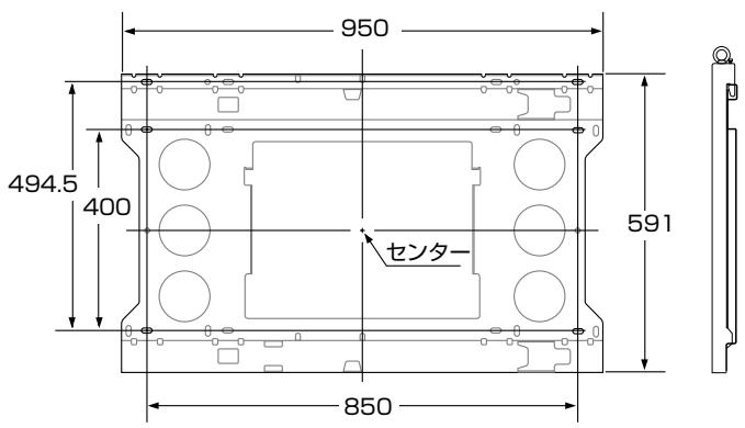
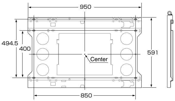
| Wall Unit Dimensions | 950 mm x 494.5 mm |
| Distance Between Brackets | 400 mm horizontal, 591 mm vertical |
| Material | Steel |
| Color | Black |
| Supported Weight | Up to 100 kg (estimated for 61" display) |
| Number of People Required for Installation | Minimum 3 people |
| Wall Fixing | 6 M8 screws or anchors (not supplied) |
| Screws Supplied | M8 screws for display attachment, M5 screws for locking |
| Tools Required | Screwdriver, wrench, drill, spirit level |
| Installation | By a qualified installer or dealer |
| Safety | Top locking screws, safety hooks, visual engagement indicator |
| Maintenance | Clean with a dry cloth; periodically check screw tightness |
| Operating Temperature | -5 °C to 35 °C (estimated) |
| Operating Humidity | 20 % to 80 % RH (estimated) |
| Unit Weight | Approximately 5 kg (estimated) |
Frequently Asked Questions - PDK-WM03 PIONEER
User questions about PDK-WM03 PIONEER
0 question about this device. Answer the ones you know or ask your own.
Ask a new question about this device
Download the instructions for your Wall mount in PDF format for free! Find your manual PDK-WM03 - PIONEER and take your electronic device back in hand. On this page are published all the documents necessary for the use of your device. PDK-WM03 by PIONEER.
USER MANUAL PDK-WM03 PIONEER
Operating instructions
Mode d'emploi
Bedienungsanleitung
壁掛けユニット・・・1個
(PDP-614MXのみ)
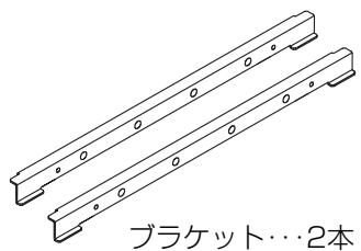

M5ネジ…2本

M8ネジ…6本
ご使用の前に
絵表示について
| W | H | D | |||
| H1 | H2 | ||||
| 61V型 | PDP-614MX | 1,470 | 880 | 164 | |
| 453.5 | 426.5 | ||||
| PDP-615PRO | 1,502 | 912 | 171 | ||
| PRO-1410HD | |||||
| PDP-615EX | 469.5 | 442.5 | |||
(单位:mm)
●縦置き設置(PDP-614MXのみ)
| W | H | D | |||
| H1 | H2 | ||||
| 61V型 | PDP-614MX | 880 | 1470 | 164 | |
| 735 | 735 | ||||
(单位:mm)
Operating Instructions
Thank you for your purchase of this Pioneer plasma display mounting unit (PDK-WM03). Please read this operating instructions carefully to ensure proper, safe use.
* This mounting unit is designed specifically for use with Pioneer 61-inch plasma displays. Please check that the plasma display can accommodate the unit before use.
Notes on Installation Work:
This product is marketed assuming that it is installed by qualified personnel with enough skill and competence.
Always have an installation specialist or your dealer install and set up the product.
PIONEER cannot assume liabilities for damage caused by mistake in installation or mounting, misuse, modification or a natural disaster.
To the Dealer and the Installer
For the safety of the customer, we ask that the installation work only be started after the strength of the mounting location has been carefully studied to be sure it can withstand the combined weight of the plasma display and mounting hardware.
Be sure that three or more persons engage in the installation work.
Be careful not to lose any screws that have been removed, extra parts, etc.
CONTENTS
Package Parts List .... Front Cover Heed the Following .... 2
■ Horizontal Installation
-
Attaching the Display Fittings to the Plasma Display .... 4
-
Attaching the Wall Mounting Unit to the Wall 4
-
Attaching the Plasma Display .... 5
■ Vertical Installation (PDP-614MX only)
-
Attaching the Bracket(s) and Display Fittings to the Plasma Display ..... 6
-
Attaching the Wall Mounting Unit to the Wall 6
-
Attaching the Plasma Display ....7
Positional Relationship Between the Wall Mounting Unit and the Display ... 10
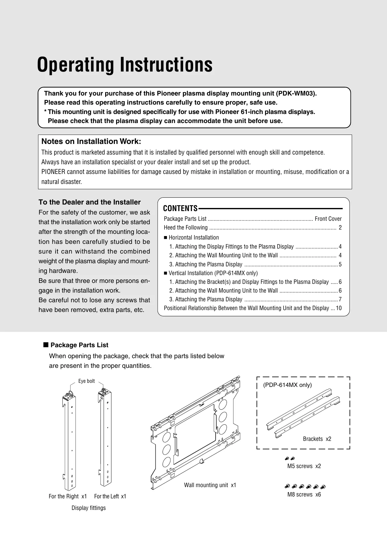
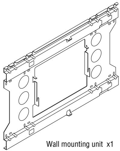
■ Package Parts List
When opening the package, check that the parts listed below are present in the proper quantities.

M5 screws x2

M8 screws x6
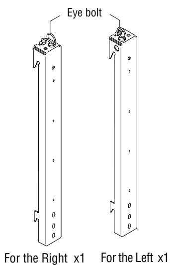
Display fittings
Before Use...
Symbols
This Operating Installations uses pictograms to indicate matters required for the installer to install the plasma display properly and safety in order to ensure proper, safe use of the product and prevent injury to yourself and others or damage to property. The pictograms and their meanings are indicated below. Be sure to understand them well before reading the rest of the manual.
WARNING

Ignoring this indication and improper handling could be the cause of personal injury such as a serious injury or death.
CAUTION

Ignoring this indication and improper handling could cause injury to a person or damage to the surrounding household belongings.
Examples of Symbols

⚠ This symbol informs that there are contents that demand caution (including warnings).
Concrete details of the caution are written within the diagram.

⊗ This symbol indicates a prohibited matter.
Concrete details of the prohibition are written within the diagram.

This symbol indicates something that must be done.
Concrete details of the prohibition are written within the diagram.

WARNING

* When installing the plasma display, be sure to make a request for service with the dealer and ensure the work is performed according to this manual. Incorrect installation may result in the plasma display falling and causing injury.

* To prevent the plasma display from falling, the strength of the installation place and the method of fastening must support the combined weight of the plasma display and the mounting unit for an extended period of time as well as withstand earthquakes. Improper installation may result in the plasma display falling and causing injury. Be sure to observe the following matters.
- An electrical outlet should be used for the power supply of the plasma display. Direct connection to a power cable is dangerous and should not be used. Please use a power outlet that can be reached to allow the insertion and withdrawal of the power plug.
- Installation for Wooden Walls
The load should by all means be carried by beams, and when the strength of the beams is insufficient, they should be strengthened. The installation should not be made to skirting or supporting members. The load should also be carried by beams when there is a steel beam suspended ceiling; installation should not be made to the ceiling suspension fittings.
- Installation for Concrete Walls
Commercial anchors that are strong enough to easily support the load of the plasma display should be used.

* To ensure safety, bolts and screws must be tightened securely. Be sure to use the supplied parts for the brackets and the other fittings.
Failure to do so may result in the plasma display falling and causing injury.

* When aligning the grooves of the display fittings to the fixed unit, check to make sure that they are securely engaged.
Failure to do so may result in the plasma display falling and causing injury.

WARNING

* Do not modify any parts. Failure to do so may result in the plasma display falling and causing injury.

* Do not use any damaged parts. Failure to do so may result in the plasma display falling and causing injury. In the event that any parts are damaged, please contact the dealer.

* This unit is made especially for use with Pioneer 61 inch and 50 inch plasma displays. Do not use with any other equipment since the equipment could fall and cause injury.

CAUTION

* Do not obstruct the ventilation holes of the plasma display. Doing so will prevent the dissipation of heat and may result a fire. Do not use the plasma display in the following ways: Do not install the plasma display in a tight place where ventilation is poor, place a cover on it, etc.

* Do not install the plasma display in front of the vents of an air conditioner or heater, or in a place where there is strong vibration. Doing so may result in fire or electrical shock.

* Do not install the plasma display in humid or dusty places, or where it will be exposed to greasy smoke or steam (such as near cooking equipment or humidifiers). Doing so may result in a fire. Do not use the plasma display outdoors. Doing so may result in a fire or electrical shock.

* Leave sufficient space around the plasma display when installing it. Failure to do so may load to head buildup within the display and could result in fire.

* Hold the plasma display in place while attaching it to the unit. Failing to do so may lead to it falling and causing injury.

* Do not apply pressure to the glass surface of the plasma display. The pressure could cause it to crack and it could cause injury.

* Do not attach screws to the plasma display without the fittings mounted. Doing so could cause breakdown.

* Never use screws other than those supplied. Use of such screws could cause breakdown.
Installation Location
Avoid rooms with a lot of dust, humidity, greasy smoke, or tobacco smoke.
Dirt will adhere to the surface of the display monitor screen and cause a deterioration in image quality.
Avoid places in which the screen is exposed to direct sunlight or illumination light.
When surrounding light hits the screen directly, the image appears washed out and is difficult to view.
Avoid places which reach high temperatures or low temperatures.
Such extreme temperatures will cause breakdown.
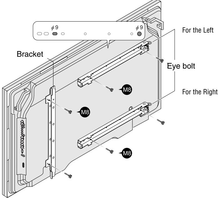
1. Attaching the Display Fittings to the Plasma Display
There are two display fittings, one for the right side, the other for the left. Mount the fittings so that their eye bolts are at the inner side.
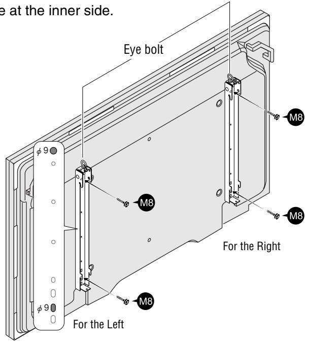
Line up the screw holes ( 9 , indicated on the diagram) at the tops and bottoms of the display fittings (one each for left and right sides) with the screw holes (M8) in the rear panel of the plasma display, and fasten the display fittings using 2 of the included M8 screws for each fitting.
Reference: (PDP-614MX only)
When using the PDK-TS06 optional stand, the display fittings can be attached with the plasma display mounted on the stand.
Remove the four M6 screws fastening the display to the stand before attaching the display fittings. When lifting the plasma display, do not allow the stand to be lifted together with the display. If the stand were to come off, it could cause injury or damage.
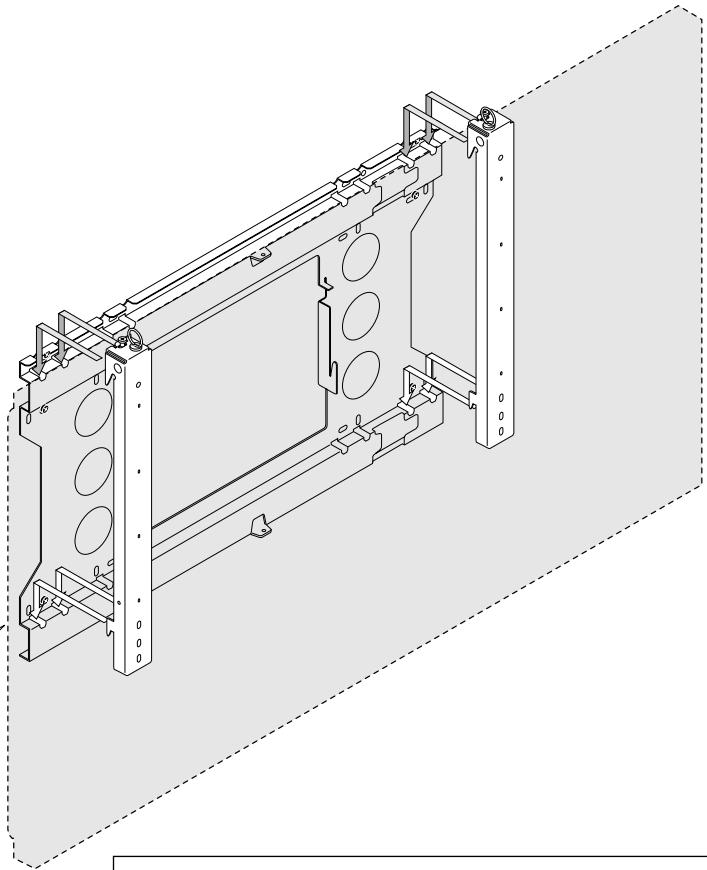
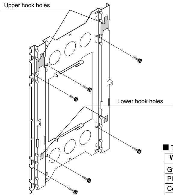
2. Attaching the Wall Mounting Unit to the Wall
Screw the wall mounting unit to the wall using commercially available anchors or the 6 M8 screws.
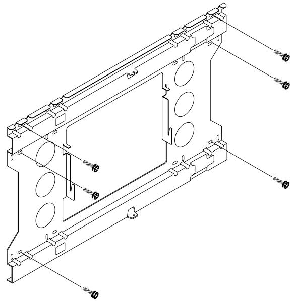
NOTE: Make sure that the anchors or screws are fastened into sections of the wall at which there are beams. (Use anchors or screws that are suited for use on the type of wall on which the unit is being mounted.) For details, see the following Table of Wall Material vs. Anchors and Screws.
■ Table of Wall Material vs. Anchors and Screws
| Wall Material | Anchor |
| Gypsum board | * Do not mount on plaster or plywood boards. Be sure to fasten into a beam. |
| Plywood | |
| Concrete | All anchors (850) or bolt plugs (300) |
| Block | Tie-Lock anchors (No. 25) |
| ALC | |
| Mortar | |
| Brick | |
| Wooden posts | Coach screws ( 8 × 50 ) |
* The extraction strength should be 500 kg or greater per position.
3. Attaching the Plasma Display
After attaching the display fittings to the plasma display, attach the plasma display to the wall mounting unit.
① Catch the upper hooks on the left and right display fittings into the grooves in the wall mounting unit.
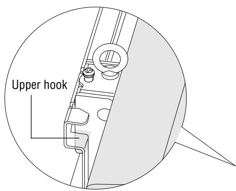
② With the upper hooks engaged in the wall mounting unit grooves, lift the plasma display directly upward about 1 cm until it stops, then push the bottom of the plasma display toward the wall to engage it with the lower hooks.
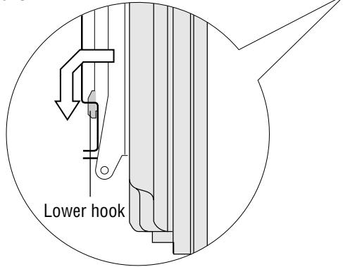
Reference:
The plasma display is properly mounted if it does not move when the lower side is pulled towards you.
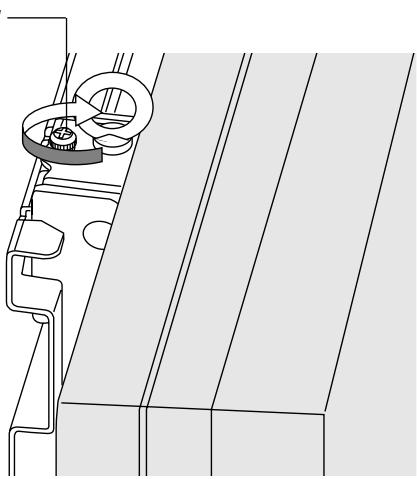
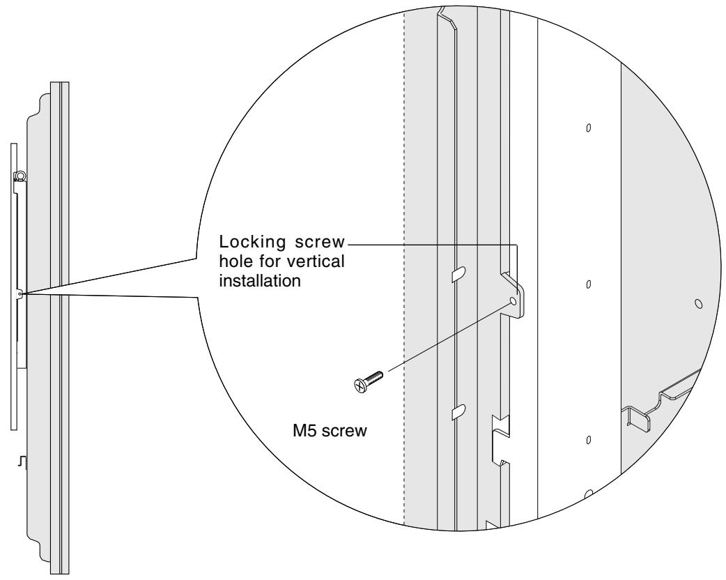
③ Tighten the locking screws at the tops of the left and right display fittings using a screw-driver.
Reference:
When installing the plasma display in a high position to which it cannot be lifted by hand, it can be suspended from the eye bolts at the tops of the display fittings and lifted with a crane or other heavy machine. Check that the eye bolts are tight before doing this.
Locking screw
CAUTION
Models PDP-615PRO, PRO-1410HD, and PDP-615EX do not support vertical installation.
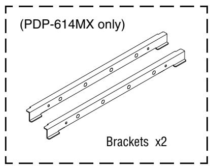
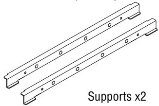
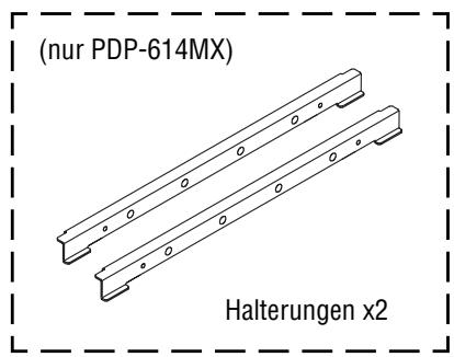
1. Attaching the Bracket(s) and Display Fittings to the Plasma Display
There are two display fittings, one for the right side, the other for the left. Mount the fittings so that their eye bolts are at the inner side. Attach the fittings so that when viewed from the rear of the plasma display, the eye bolts are positioned at the right side. Attaching the fittings in the opposite orientation will cause damage to the plasma display.
Use 2 of the included M8 screws to fasten one of the two brackets to the plasma display in the direction shown on the diagram.
2 Line up the screw holes (ø9, indicated on the diagram) in the display fittings (one each for left and right sides) with the screw holes (M8) in the rear panel of the plasma display, and fasten the display fittings using 2 of the included M8 screws for each fitting.
Reference: (PDP-614MX only)
When using the PDK-TS06 optional stand, the display fittings can be attached with the plasma display mounted on the stand.
When lifting the display, do not allow the stand to be lifted together with the display. If the stand were to come off, it could cause injury or damage.
2. Attaching the Wall Mounting Unit to the Wall
Screw the wall mounting unit to the wall using commercially available anchors or the 6 M8 screws.
Mount with the upper hook holes at the top.
NOTE: Make sure that the anchors or screws are fastened into sections of the wall at which there are beams. (Use anchors or screws that are suited for use on the type of wall on which the unit is being mounted.) For details, see the following Table of Wall Material vs. Anchors and Screws.
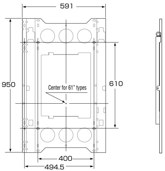
Table of Wall Material vs. Anchors and Screws
| Wall Material | Anchor |
| Gypsum board | * Do not mount on plaster or plywood boards. Be sure to fasten into a beam. |
| Plywood | |
| Concrete | All anchors (850) or bolt plugs (300) |
| Block | Tie-Lock anchors (No. 25) |
| ALC | |
| Mortar | |
| Brick | |
| Wooden posts | Coach screws ( φ 8 × 50 ) |
* The extraction strength should be 500 kg or greater per position.
3. Attaching the Plasma Display
After attaching the display fittings to the plasma display, attach the plasma display to the wall mounting unit.
Place the plasma display on a cushion or other cushioning material that has been placed on a level floor, then change the orientation as illustrated in the diagram.
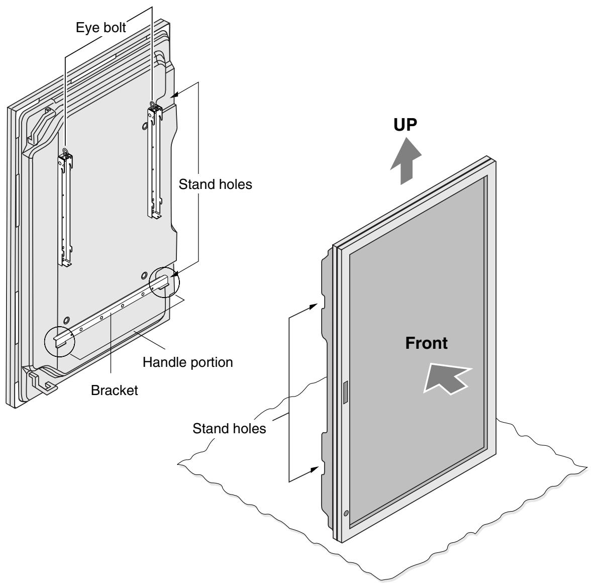
※ Use the bracket that is attached to the 61-inch plasma display as a handle.
Be sure to use gloves while doing this work as a precaution against possible injury.
※ When installing the plasma display in a high position to which it cannot be lifted by hand, it can be suspended from the eye bolts at the tops of the display fittings and lifted with a crane or other heavy machine. Check that the eye bolts are tight before doing this.
② Catch the hooks on the left and right display fittings into the grooves in the wall mounting unit.
When the upper hook is completely engaged, a white painted area will be visible in the window.
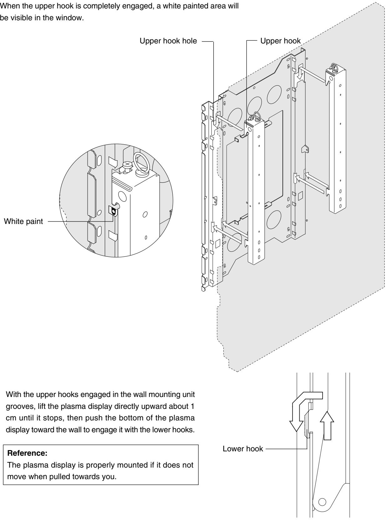
With the upper hooks engaged in the wall mounting unit grooves, lift the plasma display directly upward about 1 cm until it stops, then push the bottom of the plasma display toward the wall to engage it with the lower hooks.
Reference:
The plasma display is properly mounted if it does not move when pulled towards you.
③ Fasten the left and right display fittings using the included M5 screws.
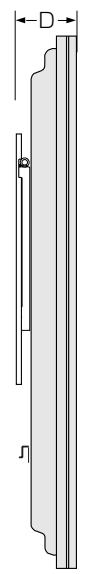
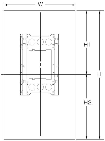
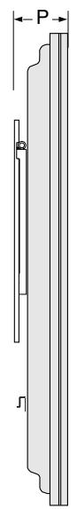
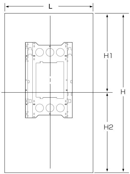
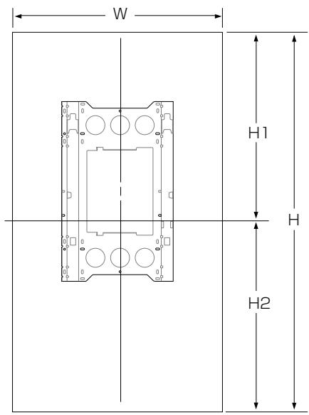
Positional Relationship Between the Wall Mounting Unit and the Display
* Horizontal installation
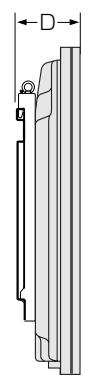
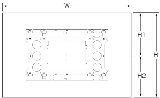
| W | H | D | |||
| H1 | H2 | ||||
| 61inch | PDP-614MX | 1,470 | 880 | 164 | |
| 453.5 | 426.5 | ||||
| PDP-615PRO PRO-1410HD PDP-615EX | 1,502 | 912 | 171 | ||
| 469.5 | 442.5 | ||||
(Unit : mm)
* Vertical installation (PDP-614MX only)

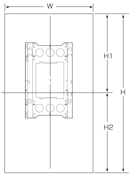
| W | H | D | |||
| H1 | H2 | ||||
| 61inch | PDP-614MX | 880 | 1470 | 164 | |
| 735 | 735 | ||||
(Unit : mm)
Mode d'emploi
(PDP-614MX uniquement)
Vis M5 x2

Vis M8 x6
Référence:
ATTENTION
| L | H | P | |||
| H1 | H2 | ||||
| 61 pouces | PDP-614MX | 1,470 | 880 | 164 | |
| 453.5 | 426.5 | ||||
| PDP-615PRO PRO-1410HD PDP-615EX | 1,502 | 912 | 171 | ||
| 469.5 | 442.5 | ||||
(Unité : mm)
* Installation verticale (PDP-614MX uniquement)
| L | H | P | |||
| H1 | H2 | ||||
| 61 pouces | PDP-614MX | 880 | 1470 | 164 | |
| 735 | 735 | ||||
(Unité : mm)
Bedienungsanleitung
M5-Schrauben x2
Bemerkung:
ACHTUNG

Viti M5 x2

Viti M8 x6
Prima dell'uso...
Simbolo
Riferimento:
PRECAUZIONE
| L | A | P | |||
| H1 | H2 | ||||
| 61 pouces | PDP-614MX | 1,470 | 880 | 164 | |
| 453.5 | 426.5 | ||||
| PDP-615PROPOR-1410HDPDP-615EX | 1,502 | 912 | 171 | ||
| 469.5 | 442.5 | ||||
(Unità : mm)
| L | A | P | |||
| H1 | H2 | ||||
| 61 pouces | PDP-614MX | 880 | 1470 | 164 | |
| 735 | 735 | ||||
(Unità : mm)
Referencia:
PRECAUCIÓN
| W | H | D | |||
| H1 | H2 | ||||
| 61 pouces | PDP-614MX | 1,470 | 880 | 164 | |
| 453.5 | 426.5 | ||||
| PDP-615PRO PRO-1410HD PDP-615EX | 1,502 | 912 | 171 | ||
| 469.5 | 442.5 | ||||
(Unidad : mm)
| W | H | D | |||
| H1 | H2 | ||||
| 61 pouces | PDP-614MX | 880 | 1470 | 164 | |
| 735 | 735 | ||||
(Unidad : mm)
AFTER-SALES SERVICE FOR PIONEER PRODUCTS
Please contact the dealer or distributor from where you purchased the product for its after-sales service (including warranty conditions) or any other information. In case the necessary information is not available, please contact the Pioneer's subsidiaries (regional service headquarters) listed below:
PLEASE DO NOT SHIP YOUR PRODUCT TO THE COMPANIES at the addresses listed below for repair without advance contact, for these companies are not repair locations.
AMERICA
PIONEER ELECTRONICS (USA) INC.
CUSTOMER SUPPORT DIVISION
P.O. BOX 1760, LONG BEACH, CA 90801-1760, U.S.A.
CUSTOMER SERVICE HOTLINE : (800) 421-1404
EUROPE
PIONEER EUROPE NV
EUROPEAN SERVICE DIVISION
HAVEN 1087, KEETBERGLAAN 1, B-9120 MELSELE, BELGIUM
ASEAN
PIONEER ELECTRONICS ASIACENTRE PTE. LTD.
SERVICE DEPARTMENT
253, ALEXANDRA ROAD #04-01 SINGAPORE 159936
JAPAN AND OTHERS
PIONEER CORPORATION (HEAD OFFICE)
CUSTOMER SUPPORT CENTER
Published by Pioneer Corporation.
Copyright © 2004 Pioneer Corporation.
All rights reserved.
パイオニア株式会社
PIONEER ELECTRONICS AUSTRALIA PTY.LTD. 178-184 Boundary Road, Braeside, Victoria 3195, Australia, TEL: 61-39-586-6300
PIONEER ELECTRONICS ASIACENTRE PTE. LTD. 253 Alexandra Road #04-01, Singapore 159936, TEL: 65-6472-1111
PIONEER HIGH FIDELITY TAIWAN CO., LTD. 13FL., No44 Chung Shan North Road, Sec.2. Taipei, Taiwan, TEL: 886-2-2521-3588
PIONEER ELECTRONICS (CHINA) LTD. Room 1704-06, 17/F World Trade Centre, 280 Gloucester Rd. Causeway Bay, Hong Kong, TEL: 852-2848-6488
PIONEER GULF FZE Lob 11-017, Jebel Ali Free Zone P.O. BOX 61226, Jebel Ali, Dubai, United Arab Emirates, TEL: 971-4-8815756
PIONEER ELECTRONICS DE MEXICO S.A. DE C.V. Blvd. Manuel Avila Camacho 138 10 piso Col.Lomas de Chapultepec, Mexico, D.F. 11000 TEL: 55-9178-4270

- ご使用の前に
- 絵表示について
- OPERATING INSTRUCTIONS
- NOTES ON INSTALLATION WORK
- TO THE DEALER AND THE INSTALLER
- CONTENTS
- PACKAGE PARTS LIST
- BEFORE USE
- SYMBOLS
- WARNING
- CAUTION
- EXAMPLES OF SYMBOLS
- INSTALLATION LOCATION
- ATTACHING THE DISPLAY FITTINGS TO THE PLASMA DISPLAY
- REFERENCE: (PDP-614MX ONLY)
- ATTACHING THE WALL MOUNTING UNIT TO THE WALL
- ATTACHING THE PLASMA DISPLAY
- REFERENCE
- ATTACHING THE BRACKET(S) AND DISPLAY FITTINGS TO THE PLASMA DISPLAY
- POSITIONAL RELATIONSHIP BETWEEN THE WALL MOUNTING UNIT AND THE DISPLAY
- MODE D'EMPLOI
- ATTENTION
- BEDIENUNGSANLEITUNG
- BEMERKUNG
- ACHTUNG
- PRIMA DELL'USO
- SIMBOLO
- RIFERIMENTO
- PRECAUZIONE
- REFERENCIA
- PRECAUCIÓN
- AFTER-SALES SERVICE FOR PIONEER PRODUCTS
- AMERICA
- EUROPE
- ASEAN
- JAPAN AND OTHERS
- パイオニア株式会社
Brand : PIONEER
Model : PDK-WM03
Category : Wall mount