
PDK-WM01 - Wall mount PIONEER - Free user manual and instructions
Find the device manual for free PDK-WM01 PIONEER in PDF.
| Product Type | Wall mount for plasma screen |
| Brand | Pioneer |
| Model | PDK-WM01 |
| Compatibility | Pioneer plasma screens (size not specified) |
| Maximum load capacity | Approximately 50 kg (estimated) |
| Material | Steel (estimated) |
| Color | Black (estimated) |
| VESA standard | Compatible with standard plasma screen mounting holes (not specified) |
| Installation | Solid wall fixation, assembly by at least two people |
| Safety | Bracket designed exclusively for indoor use, avoid vibrations and shocks |
| Maintenance and cleaning | Clean with a dry cloth, do not use abrasive products |
| Estimated lifespan | Approximately 5 years before inspection by a professional |
| Repairability | Call a specialized installer for any repairs |
| Included accessories | Mounting screws, installation manual (not detailed) |
| Warranty | Check with the retailer (not specified) |
Frequently Asked Questions - PDK-WM01 PIONEER
User questions about PDK-WM01 PIONEER
0 question about this device. Answer the ones you know or ask your own.
Ask a new question about this device
Download the instructions for your Wall mount in PDF format for free! Find your manual PDK-WM01 - PIONEER and take your electronic device back in hand. On this page are published all the documents necessary for the use of your device. PDK-WM01 by PIONEER.
USER MANUAL PDK-WM01 PIONEER
Operating instructions
Mode d'emploi
Bedienungsanleitung
3 PDP
①
PDP
(2)
PDP
(3) PDP
4
PDP
PDP M8 6


5
4
6 PDP
① PDP ②

2

①
(2)
7
PDP

5mm
3
M 6 × 1 4 mm 2
8
M6 x 14mm
( 2 )
2 amp; PDP - 4 3 4 BX / PDP - 4 3 4 TX 1 amp; M 6 × 1 4 mm

1
2
PDP
2
3
2
4

PDP
5

2
9.3 kg
42.6 kg
50.8 kg
43.3 kg
42.3 kg
PDP-434HD PDP-434HDV
PDP-504HD PDP-504HDV
PDP-434BX
PDP-434TX
PDP-504HD/PDP-504HDV/PDP-434HD/PDP-434HDV
mm
50
PDP-434BX/PDP-434TX
Thank you for buying Pioneer's product.
Please read through the Operating Instructions to learn how to operate your model safely and properly.
Please be advised to keep the Operating Instructions in your place for future reference.
Installation
- Consult your dealer if you encounter any difficulties with this installation.
- Pioneer is not liable for any damage resulting from improper installation, improper use, modification, or natural disasters.
Note to Construction Companies
Prior to installing this product, please read Pioneer's technical manual thoroughly and heed its content.
Pioneer shall not be liable in any way for any accidents or damage resulting from other than the specified assembly, mounting and usage, from remodeling, or from natural disasters or the like.
Contents
Cautions 8
Checking the Parts 9
Service Parts List 9
Installation Procedure 9
External Dimension Diagram 13

CAUTION
This symbol refers to a hazard or unsafe practice which can result in personal injury or property damage.
Cautions

This product is exclusively for use with the plasma display.
It should not be used for any other purpose, such as for holding a plasma display, or remodeled in any way.
Improper installation is extremely dangerous because it may result in it falling over or other accident.
Installation Location
- Select a location that is strong enough to support the weight of the stand and the displays.
- Do not install it at a place where people can easily hang from it or lean on it.
- Do not install it outdoors, at a hot spring, or near a beach.
- Do not install the stand where it may be subjected to vibration or shock.
- There are cases where it cannot be installed because of the structural strength of the wall, so consult with an expert installer.
- Thoroughly read and always follow the plasma display operating instructions for more information about the installation location.
Assembling and Installation
- Assemble the stand in accordance with the assembly instructions and securely attach all screws at the designated locations.
There have been cases where unforeseen accidents such as the equipment breaking or falling over occurred after the installation of the display because the stand was not installed as instructed.
- The display must always be installed by two or more people to assure it is installed safely.
- Before installation, turn off the power for the display and peripheral devices then remove the power cord plug from the power outlet.
Make sure that the screws used to attach all parts never become loose, because a loosened screw may result in it falling over or other accident.
If you discover a fault or malfunction, immediately have an expert installer perform repairs.
There is a danger of the interior of metal fittings of the display, parts attached to the wall, or other places that cannot be seen being damaged so that the display falls over. Therefore, when inspecting or repairing the display, or when performing interior finishing work in your shop, be sure to ask an expert installer to inspect these places. We recommend that if possible, you ask an expert installer to perform inspections at regular intervals.
If the metal fittings of the display are used for a long time, the environment may cause change over time, reducing their strength. After five years, ask an expert installer to inspect it to make sure that it can be used without any problems.
Checking the Parts
Check the parts before beginning assembly.
Note
- Screws used to fix the wall-hanging metal fitting firmly to the wall surface are not included. Purchase these separately.
- Philips driver separately.
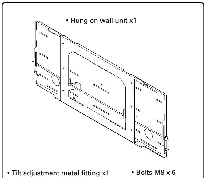
- Hexagon wrench x 1 (Opposite side 6 mm for M8 use)
- Stencil x 1
- Operating instructions (this document) x 1
Service Parts List
| Mark | No. | Description | Parts No. |
| BOLT M8 | AZB1435- | ||
| SCREW M6 | AZB1438- | ||
| PACKING SET | AZH1158- | ||
| OPERATING INSTRUCTIONS | AZR1074- | ||
| TILT ADJUSTMENT | AZR2560- | ||
| METAL FITTING |
Installation Procedure
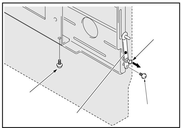
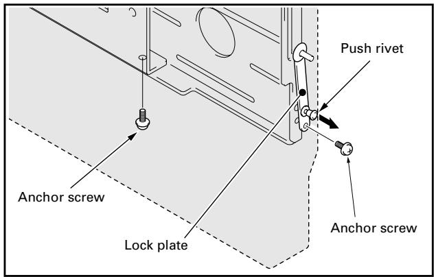
1 Removing the push rivet of the lock plate and the bottom anchor screw (M6 x 14mm) (2 locations: left and right sides).
① Move the push rivet of the lock plate to its unlocked position so the lock plate is in the condition shown in the figure.
② Remove the anchor screw from the bottom.
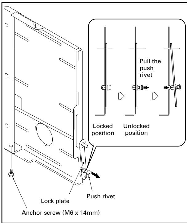
Note
Be careful not to lose the 2 anchor screws (M6 x 14mm) because they will be used later.
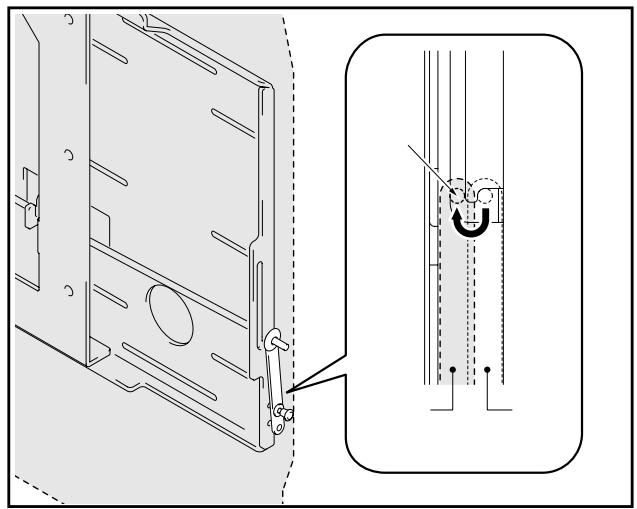
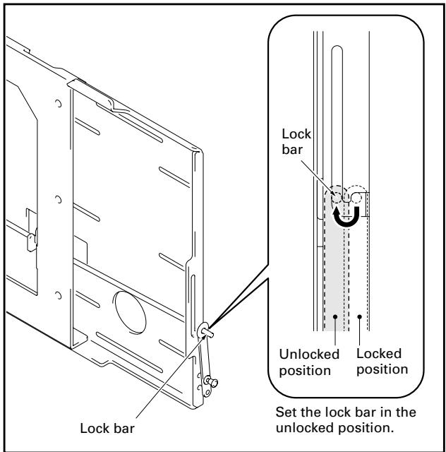
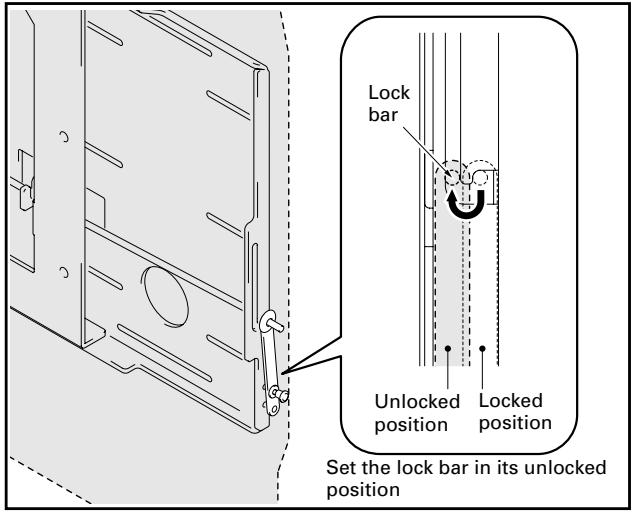
2 Releasing the lock bar (2 locations: left and right sides).
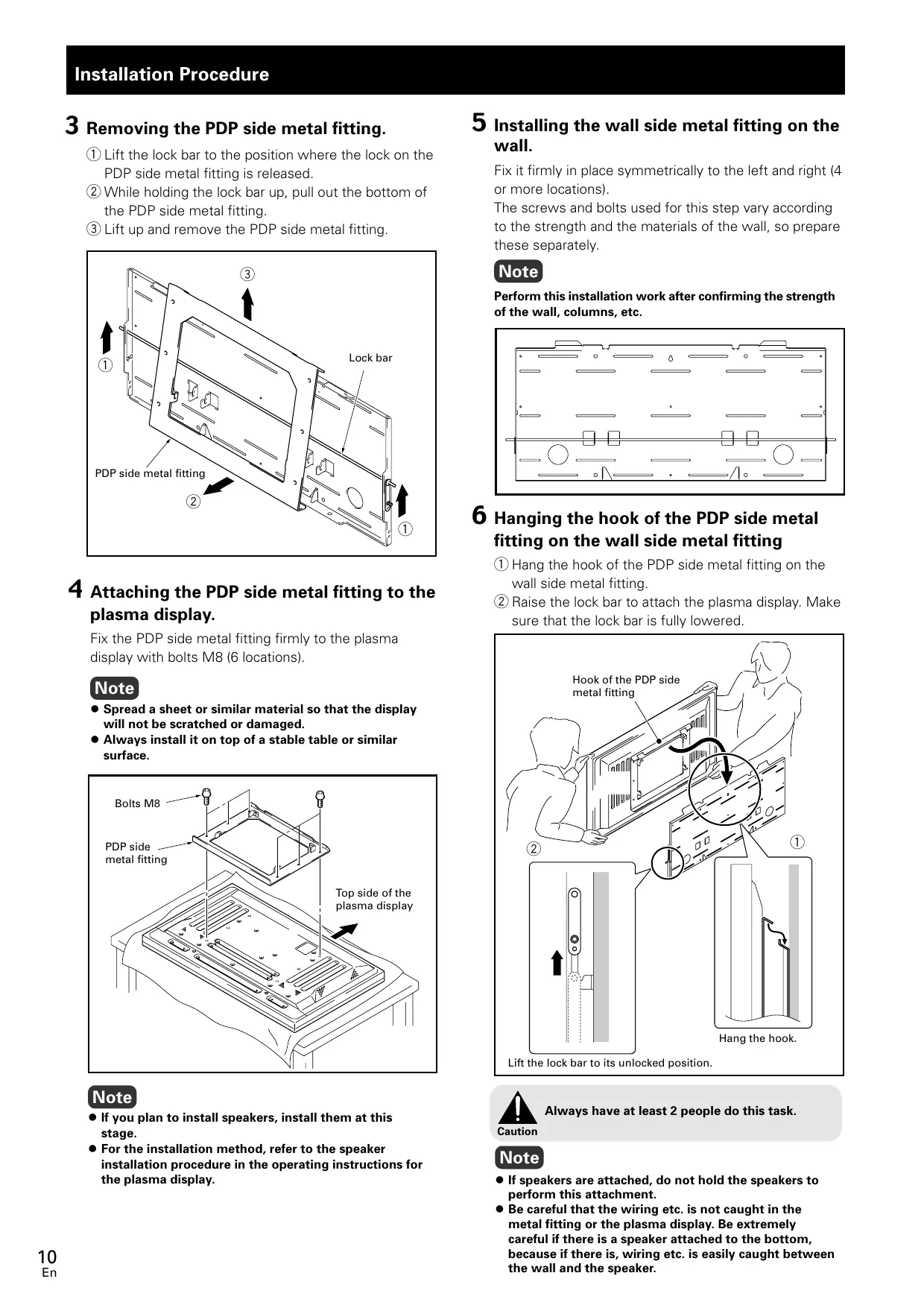
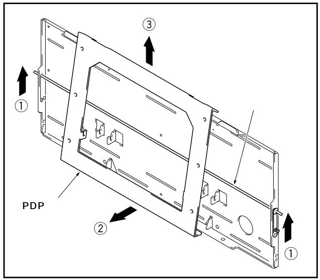
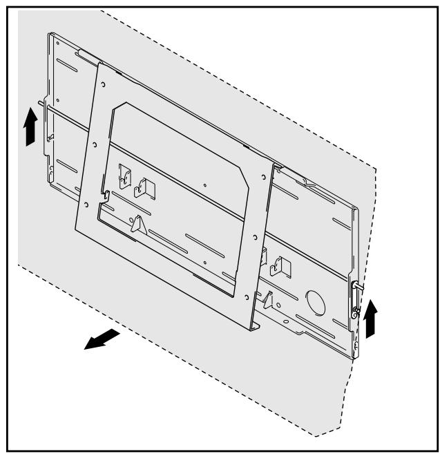
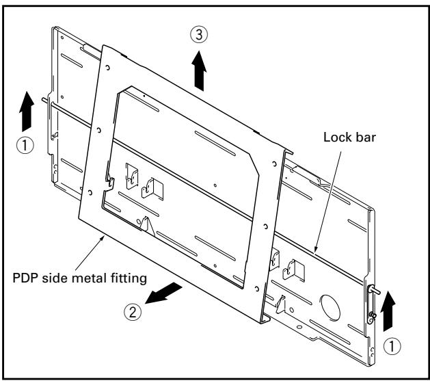
3 Removing the PDP side metal fitting.
① Lift the lock bar to the position where the lock on the PDP side metal fitting is released.
(2) While holding the lock bar up, pull out the bottom of the PDP side metal fitting.
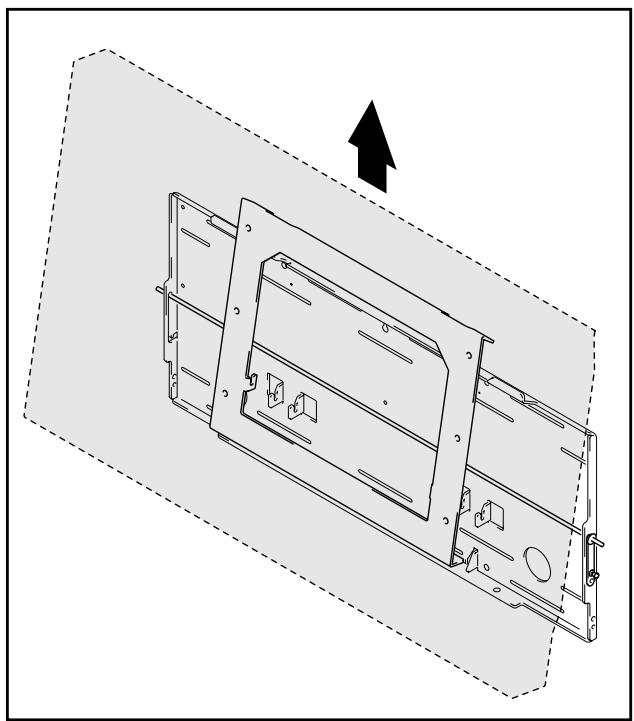
③ Lift up and remove the PDP side metal fitting.
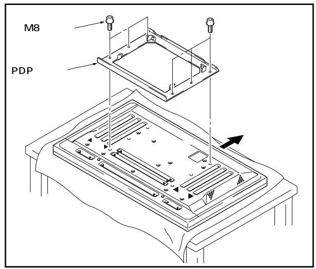
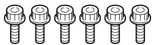
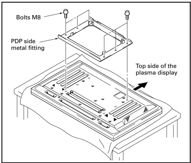
4 Attaching the PDP side metal fitting to the plasma display.
Fix the PDP side metal fitting firmly to the plasma display with bolts M8 (6 locations).
Note
- Spread a sheet or similar material so that the display will not be scratched or damaged.
- Always install it on top of a stable table or similar surface.
Note
- If you plan to install speakers, install them at this stage.
- For the installation method, refer to the speaker installation procedure in the operating instructions for the plasma display.
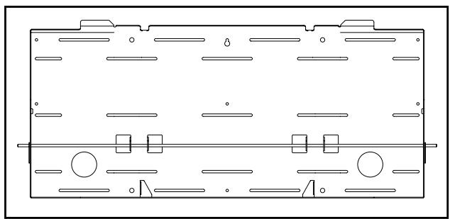
5 Installing the wall side metal fitting on the wall.
Fix it firmly in place symmetrically to the left and right (4 or more locations).
The screws and bolts used for this step vary according to the strength and the materials of the wall, so prepare these separately.
Note
Perform this installation work after confirming the strength of the wall, columns, etc.
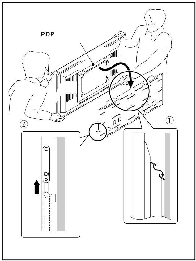
6 Hanging the hook of the PDP side metal fitting on the wall side metal fitting
① Hang the hook of the PDP side metal fitting on the wall side metal fitting.
(2) Raise the lock bar to attach the plasma display. Make sure that the lock bar is fully lowered.
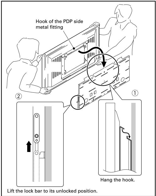

Always have at least 2 people do this task.
Note
- If speakers are attached, do not hold the speakers to perform this attachment.
- Be careful that the wiring etc. is not caught in the metal fitting or the plasma display. Be extremely careful if there is a speaker attached to the bottom, because if there is, wiring etc. is easily caught between the wall and the speaker.
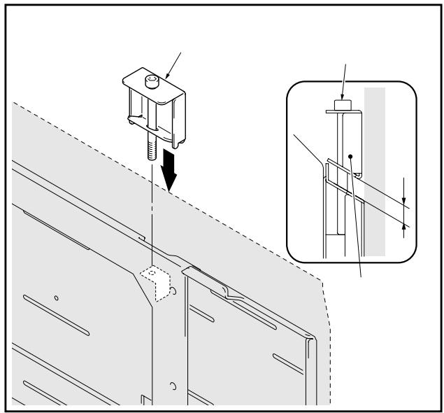
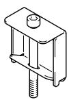
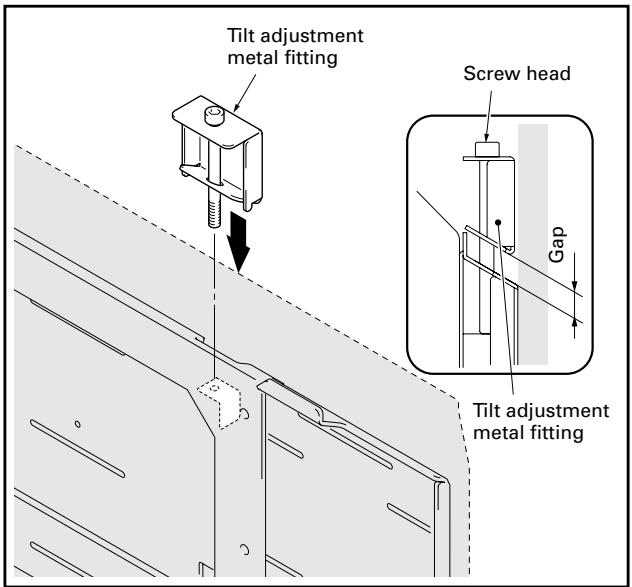
7 Fine adjustment of the vertical tilt of the plasma display.
If the plasma display is slightly tilted from the vertical after it is installed on the wall, you can adjust this tilt by attaching the tilt adjustment metal fitting. Insert the tilt adjustment metal fitting in the notch on the top surface of the PDP side metal fitting that is tilted downward and attach it by rotating the screw.
① Rotate the screw until the gap between the wall side metal fitting and the tilt adjustment metal fitting disappears. When the gap between the wall side metal fitting and the tilt adjustment metal fitting has disappeared, the screw becomes difficult to rotate and begins to lift up the plasma display.
② Rotate the screw to adjust the tilt.
Note
The range that the tilt can be adjusted by the screw is about 5mm of the external dimension of the plasma display and the screw rotates about 3 times. Be careful not to rotate the screw too much. If the screw is turned too much, the metal fitting may be damaged.
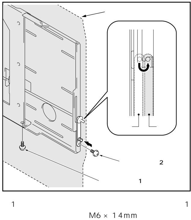
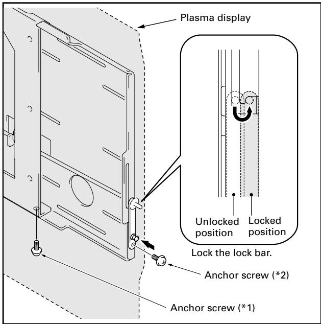
8 Locking the lock bar and fixing the lock plate firmly in place with push rivet and the anchor screw (M6 x 14mm) removed in step 1 (2 locations: left and right sides).
If you cannot fix the push rivet in place from the side, fix it in place from the bottom with the anchor screw (M6 x 14mm) (2 locations: left and right sides).
1 If there are speakers installed on both sides, fix it in place with the anchor screw (M6 x 14mm) removed in step 1.
2 If there is a speaker installed on the bottom, fix it in place with the anchor screw (M6 x14mm) removed in step 1.
When removing the plasma display

Caution
Before beginning this procedure, turn off the power to the plasma display and peripheral devices and remove their power plugs from the outlets. As necessary, also remove connecting cables.
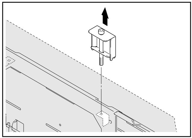
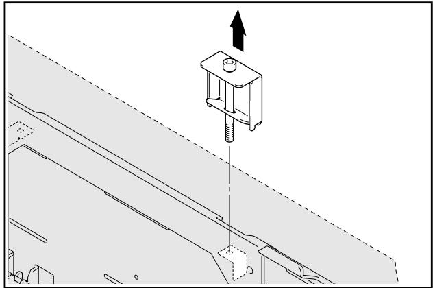
1 Loosening the screw on the tilt adjustment metal fitting.
Note
Removing the plasma display without removing the tilt adjustment metal fitting may scratch the wall.
2 Removing the push rivet and the anchor screws that are holding the lock plate, and the anchor screws that are holding the PDP metal fitting (2 locations: left and right sides).
3 Unlocking the lock bar (2 locations: left and right sides).
4 Raising the lock bar and pulling the bottom of the plasma display forward.
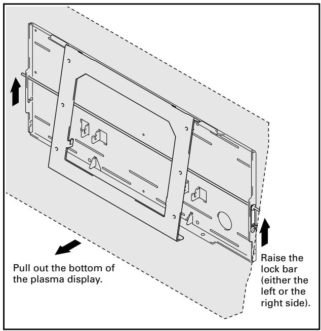

Caution
Pull out the bottom of the plasma display very carefully so that the hook on the PDP side metal fitting is not displaced.
5 Raising and removing the plasma display.
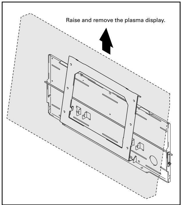

Caution
Always have at least 2 people do this task.
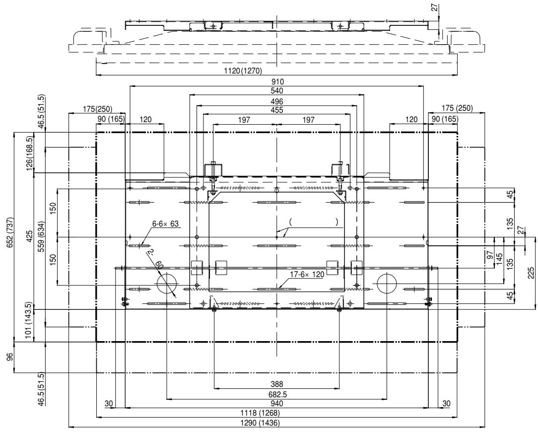
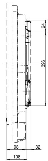
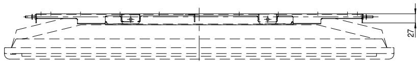
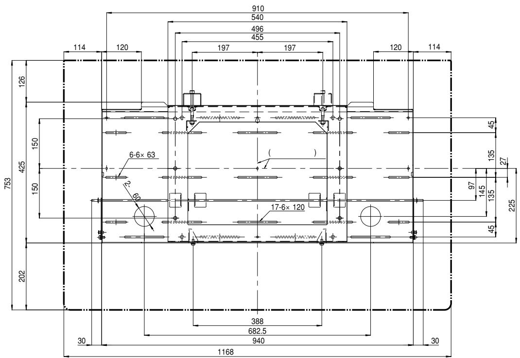
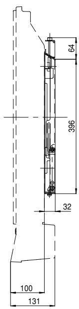
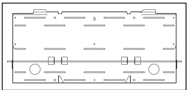
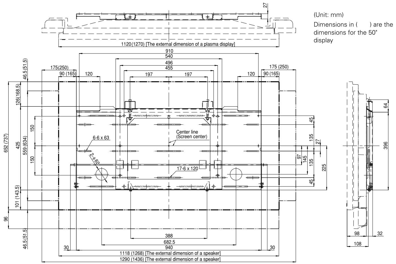
External Dimension Diagram
Weight
9.3 kg (20.5 lbs) (only metal fittings)
42.6 kg (93.9 lbs) (metal fittings + plasma display
50.8 kg (112.0 lbs) (metal fittings + plasma display
Published by Pioneer Corporation. Copyright © 2003 Pioneer Corporation. All rights reserved.
八才二株式会社
153-8654
1 4 1
PIONEER CORPORATION 4-1, Meguro 1-Chome, Meguro-ku, Tokyo 153-8654, Japan
PIONEER ELECTRONICS (USA) INC. P.O.BOX 1540, Long Beach, California 90801-1540, U.S.A., TEL: 1-310-952-2111
PIONEER EUROPE NV MULTIMEDIA DIVISION Pioneer House Hollbush Hill, Stoke Poqes, Slough SL2 4QP, U.K., TEL: 44-1753-789-789
PIONEER ELECTRONICS AUSTRALIA PTY.LTD. 178-184 Boundary Road, Braeside, Victoria 3195, Australia, TEL: 61-39-586-6300
PIONEER ELECTRONICS ASIACENTRE PTE. LTD. 253 Alexandra Road #04-01, Singapore 159936, TEL: 65-6472-1111
PIONEER HIGH FIDELITY TAIWAN CO., LTD. 13FL., No44 Chung Shan North Road, Sec.2. Taipei, Taiwan, TEL: 886-2-2521-3588
PIONEER ELECTRONICS (CHINA) LTD. Room 1704-06, 17/F World Trade Centre, 280 Gloucester Rd. Causeway Bay, Hong Kong, TEL: 852-2848-6488
PIONEER GULF FZE Lob 11-017, Jebel Ali Free Zone P.O. BOX 61226, Jebel Ali, Dubai, United Arab Emirates, TEL: 971-4-8815756
PIONEER ELECTRONICS DE MEXICO S.A. DE C.V. Blvd. Manuel Avila Camacho 138 10 piso Col.Lomas de Chapultepec, Mexico, D.F. 11000 TEL: 55-9178-4270
- INSTALLATION
- NOTE TO CONSTRUCTION COMPANIES
- CONTENTS
- CAUTION
- CAUTIONS
- INSTALLATION LOCATION
- ASSEMBLING AND INSTALLATION
- CHECKING THE PARTS
- NOTE
- SERVICE PARTS LIST
- INSTALLATION PROCEDURE
- 3 REMOVING THE PDP SIDE METAL FITTING
- 4 ATTACHING THE PDP SIDE METAL FITTING TO THE PLASMA DISPLAY
- 5 INSTALLING THE WALL SIDE METAL FITTING ON THE WALL
- 6 HANGING THE HOOK OF THE PDP SIDE METAL FITTING ON THE WALL SIDE METAL FITTING
- 7 FINE ADJUSTMENT OF THE VERTICAL TILT OF THE PLASMA DISPLAY
- 8 LOCKING THE LOCK BAR AND FIXING THE LOCK PLATE FIRMLY IN PLACE WITH PUSH RIVET AND THE ANCHOR SCREW (M6 X 14MM) REMOVED IN STEP 1 (2 LOCATIONS: LEFT AND RIGHT SIDES)
- WHEN REMOVING THE PLASMA DISPLAY
- 1 LOOSENING THE SCREW ON THE TILT ADJUSTMENT METAL FITTING
- EXTERNAL DIMENSION DIAGRAM
- WEIGHT
- 八才二株式会社
Brand : PIONEER
Model : PDK-WM01
Category : Wall mount