
PDK-WT02 - Wall mount PIONEER - Free user manual and instructions
Find the device manual for free PDK-WT02 PIONEER in PDF.
| Product Type | Wall mount for plasma screen |
| Brand | PIONEER |
| Model | PDK-WT02 |
| Compatibility | Pioneer plasma screens PDP-506XDE, PDP-506FDE, PDP-506HDG, PDP-436XDE, PDP-436FDE, PDP-436HDG |
| Maximum load capacity | 50 kg (based on weight of compatible screens) |
| Material | Steel |
| Finish | Black |
| Installation | Wall-mounted, requires at least two people, screws and wall plugs included |
| Safety | Do not use with other models; check by a specialized installer after 5 years |
| Maintenance and cleaning | Clean with a dry soft cloth; do not use abrasive products |
| Spare parts and repairability | Contact a specialized installer for any repair or replacement |
| General information | Use exclusively as plasma screen mount; do not modify the product |
Frequently Asked Questions - PDK-WT02 PIONEER
User questions about PDK-WT02 PIONEER
0 question about this device. Answer the ones you know or ask your own.
Ask a new question about this device
Download the instructions for your Wall mount in PDF format for free! Find your manual PDK-WT02 - PIONEER and take your electronic device back in hand. On this page are published all the documents necessary for the use of your device. PDK-WT02 by PIONEER.
USER MANUAL PDK-WT02 PIONEER
Operating instructions
Mode d'emploi
Bedienungsanleitung
Thank you for buying Pioneer's product.
Please read through the Operating Instructions to learn how to operate your model safely and properly.
Please be advised to keep the Operating Instructions in your place for future reference.
IMPORTANT NOTICE
Record the model number and serial number of this equipment below.
Model No. PDK-WT02 Serial No.
Keep this number for future use.
WARNING
To prevent a fire hazard, do not place any naked flame sources (such as a lighted candle) on the equipment. D3-4-2-1-7a_
D3-4-2-1-7a_A_En
Installation
- Consult your dealer if you encounter any difficulties with this installation.
- Pioneer is not liable for any damage resulting from improper installation, improper use, modification, or natural disasters.
Note to Construction Companies
Prior to installing this product, please read Pioneer's technical manual thoroughly and heed its content.
Pioneer shall not be liable in any way for any accidents or damage resulting from other than the specified assembly, mounting and usage, from remodeling, or from natural disasters or the like.
Contents
Cautions 8
Confirming the Parts Provided 9
Installation Procedure 9
Adjusting the Angle 12
Specifications 12
Dimension Diagram 13

CAUTION
This symbol refers to a hazard or unsafe practice which can result in personal injury or property damage.
Cautions

This product is a hung on wall unit for plasma displays (PDP-506XDE / PDP-506FDE / PDP-506HDG / PDP-436XDE / PDP-436FDE / PDP-436HDG) from Pioneer. Use with other model is capable of resulting in instability causing possible injury. For further information, please contact the store where you purchased your display.
It should not be used for any other purpose, such as for holding a plasma display, or remodeled in any way.
Improper installation is extremely dangerous because it may result in it falling over or other accident.
Installation Location
- Select a vertical location that is strong enough to support the weight of the wall mount and the plasma display. Product weight is listed on page 12.
- Do not install it at a place where people can easily hang from it or lean on it.
- Do not install it outdoors, at a hot spring, or near a beach.
- Do not install where vibration or shock may occur.
- There are cases where it cannot be installed because of the structural strength of the wall, so consult with an expert installer.
- Thoroughly read and always follow the plasma display operating instructions for more information about the installation location.
Assembling and Installation
- Assemble in accordance with the assembly instructions and securely attach all screws at the designated locations.
There have been cases where unforeseen accidents such as the equipment breaking or falling over due to incorrect installation have occurred. - The display must always be installed by two or more people to assure it is installed safely.
- Before installation, turn off the power for the display and peripheral devices then remove the power cord plug from the power outlet.
Make sure that the screws used to attach all parts never become loose, because a loosened screw may result in it falling over or other accident.
If you discover a fault or malfunction, immediately have an expert installer perform repairs.
There is a danger of the hung on wall unit, parts attached to the wall, or other places that cannot be seen being damaged so that the plasma display falls over. Therefore, when inspecting or repairing the display, or when performing interior finishing work in your shop, be sure to ask an expert installer to inspect these places. We recommend that if possible, you ask an expert installer to perform inspections at regular intervals.
If the hung on wall unit is used for a long time, the environment may cause change over time, reducing its strength. After five years, ask an expert installer to inspect it to make sure that it can be used without any problems.
Confirming the Parts Provided
Before assembly, check to make sure that none of the parts provided are missing.
Note
- The hexagonal wrench and the operating instructions will be necessary to reset the angle and for removal. After using them, please retain them carefully.
- Screws to be used for wall installation are not included. Obtain them separately.
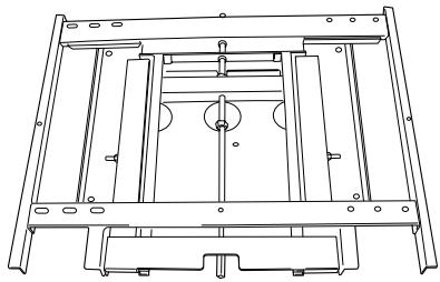
- Hung on wall unit

- Spacer × 4


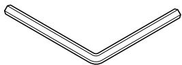
- Hexagon wrench × 1
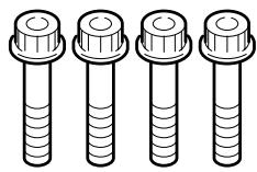
- Bolts M8
(M8 × 40 mm (1-9/16 inch): silver) ×4

- Operating instructions (this document) x 1
Installation Procedure
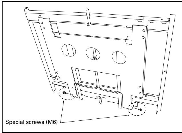
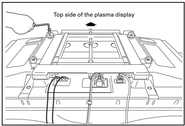
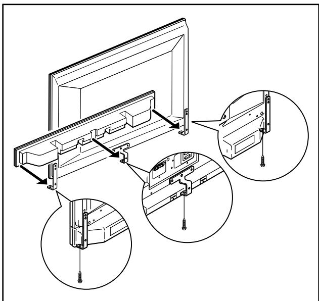
1 Remove the special screws (2 locations) from the bottom of the hung on wall unit.
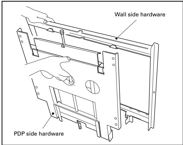
2 Remove the hardware on the wall side and the hardware on the PDP side.
3 Attach the PDP side hardware to the plasma display.
Note
- Cover the display with a sheet or similar protective material to protect it from scratches or other damage.
- Be sure to attach it on top of a flat table or similar surface.
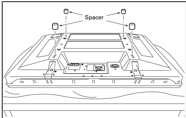
① Place the spacers (4 locations).
Place the spacers as shown in the figure below.
Note
Place them so that the holes in the spacers are aligned with the holes in the plasma display.
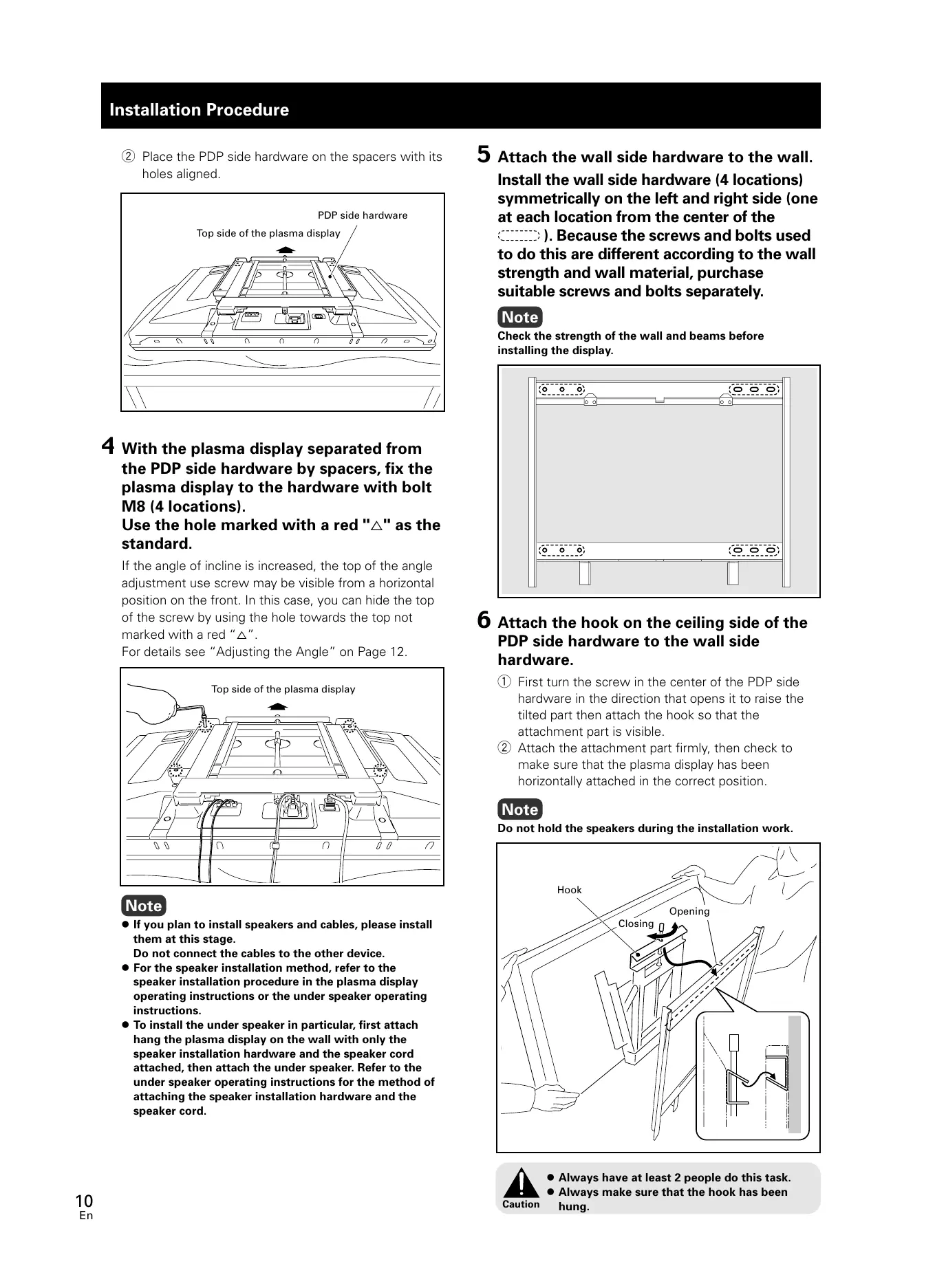
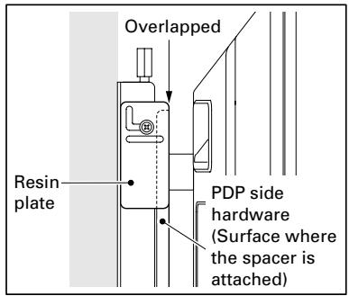
② Place the PDP side hardware on the spacers with its holes aligned.
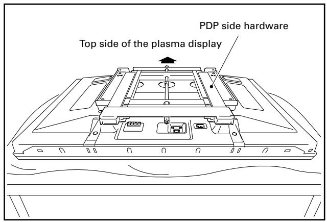
4 With the plasma display separated from the PDP side hardware by spacers, fix the plasma display to the hardware with bolt M8 (4 locations).
Use the hole marked with a red "△" as the standard.
If the angle of incline is increased, the top of the angle adjustment use screw may be visible from a horizontal position on the front. In this case, you can hide the top of the screw by using the hole towards the top not marked with a red “ ”.
For details see "Adjusting the Angle" on Page 12.
Note
- If you plan to install speakers and cables, please install them at this stage.
Do not connect the cables to the other device.
- For the speaker installation method, refer to the speaker installation procedure in the plasma display operating instructions or the under speaker operating instructions.
- To install the under speaker in particular, first attach hang the plasma display on the wall with only the speaker installation hardware and the speaker cord attached, then attach the under speaker. Refer to the under speaker operating instructions for the method of attaching the speaker installation hardware and the speaker cord.
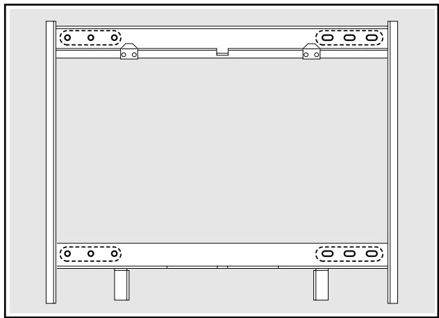
5 Attach the wall side hardware to the wall. Install the wall side hardware (4 locations) symmetrically on the left and right side (one at each location from the center of the ). Because the screws and bolts used to do this are different according to the wall strength and wall material, purchase suitable screws and bolts separately.
Note
Check the strength of the wall and beams before installing the display.
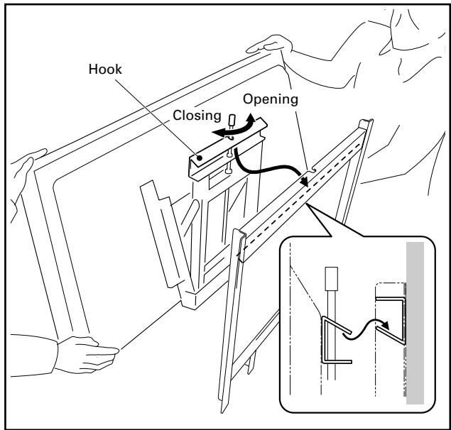
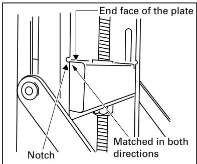
6 Attach the hook on the ceiling side of the PDP side hardware to the wall side hardware.
① First turn the screw in the center of the PDP side hardware in the direction that opens it to raise the tilted part then attach the hook so that the attachment part is visible.
② Attach the attachment part firmly, then check to make sure that the plasma display has been horizontally attached in the correct position.
Note
Do not hold the speakers during the installation work.
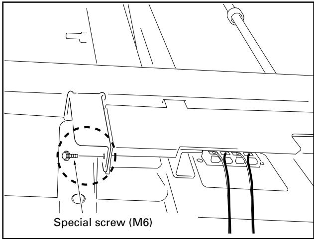
7 Fix the bottom of the hardware with the special screws removed at step 1 (one on the left and one on the right).
8 Install the under speaker (PDP-S39).
① Connect the speaker cord to the terminal on the speaker.
② Place the speaker installation hardware on the speaker and using the screws that come with the speaker, anchor both from the bottom (2 locations on the left and right).
Note
Be sure to install the speaker with the hardware attached vertically.
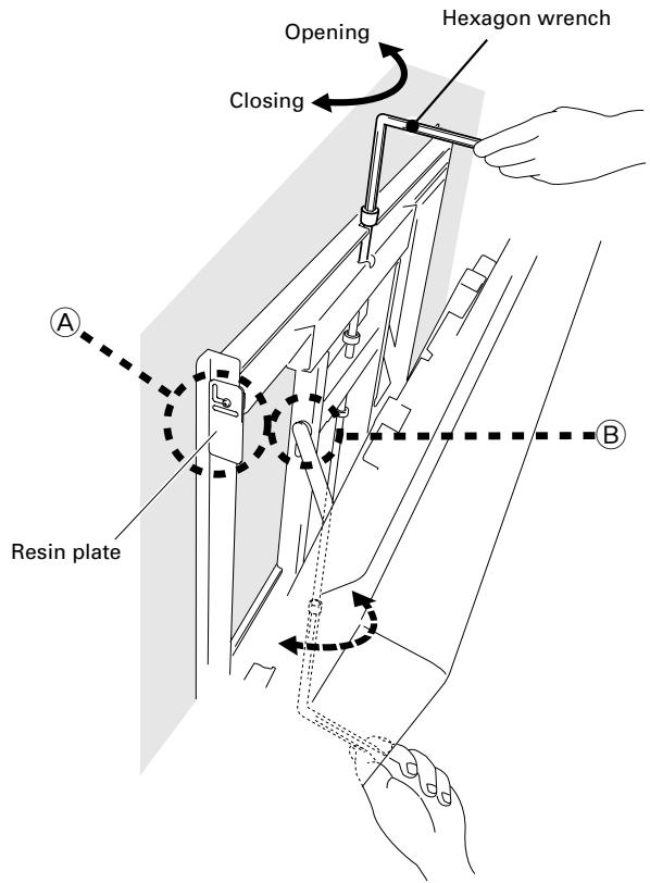
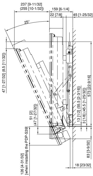
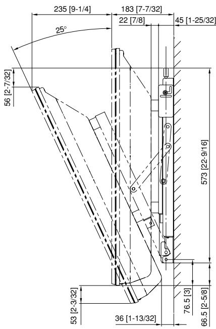
Adjusting the Angle
This installation hardware allows the display to be directed downwards freely at any angle from the vertical to 25^ .
This adjustment must always be done by 2 people.
Adjust the angle by rotating the screws at the center top and center bottom of the wall side hardware to the left or right.
Note
- If the angle is increased while you are adjusting the angle using the screw at the center of the bottom, it is difficult to turn the screw. When this happens, adjust it at the center of the upper.
- Turn the screws very carefully to avoid damaging the wall.
- When a screw becomes tight at either end of the adjustment range, do not turn the adjustment screw any further, because if you do, you will apply excessive force, deforming the screw.

When vertical (side view)
When it is in this state, do not turn the adjustment screw any further in the closing direction.

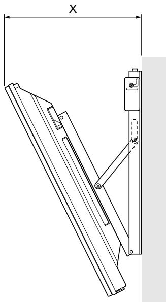
When inclined at 25^
When it is in this state, do not turn the adjustment screw any further in the opening direction.
Measuring the opening distance X enables approximate angle values to be determined.
Tilt Angle Criteria
Unit: mm (inch)
| Angle | X | |||
| Standard holes of 50-inch model | Standard holes of 43-inch model | Upper holes of 43-inch model | One body type standard hole | |
| 5° | 192 (7-9/16) | 188 (7-13/32) | 191 (7-17/32) | 212 (8-11/32) |
| 10° | 246 (9-11/16) | 238 (9-3/8) | 244 (9-19/32) | 262 (10-5/16) |
| 15° | 298 (11-23/32) | 287 (11-5/16) | 296 (11-21/32) | 310 (12-7/32) |
| 20° | 348 (13-11/16) | 334 (13-5/23) | 346 (13-5/8) | 357 (14-1/16) |
Angle of incline and appearance of the screw for angle adjustment from a horizontal position on the front
| Standard hole | Upper hole | |||
| PDP-506XDE | 23° or more | visible | to 25° | invisible |
| PDP-506FDE | ||||
| PDP-506HDG | ||||
| PDP-436XDE | 16° or more | visible | 22° or more | visible |
| PDP-436FDE | ||||
| PDP-436HDG | ||||
| One body type plasma display | 15° or more | visible | 21° or more | visible |
Specifications
External dimensions 740 (W) x 573 (H) x 67 (D) mm (29-1/8 (W) x 22-9/16 (H) x 2-5/8 (D) inch)
Weight 13.8 kg (30.4 lbs)
- The above specifications and exterior may be modified without prior notice to improve the product.
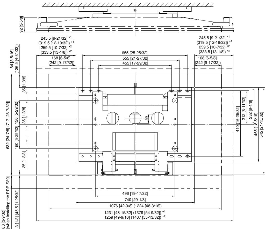
When installing speakers on both sides of the plasma display or when installing speaker at the bottom of the plasma display
Unit: mm [inch]
Dimensions in ( ) are the
dimensions for the 50 inch model
1 Flush installation: Attached with the speakers in close contact with the display.
2 Air installation: Attached with a space of approximately 15 mm (19/32 inch) between the speakers and the display.
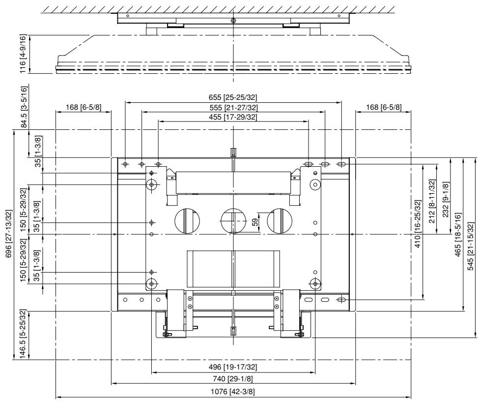
When installing the one body type plasma display
Unit: mm [inch]
Model N. PDK-WT02 Serial No.
AFTER-SALES SERVICE FOR PIONEER PRODUCTS
Please contact the dealer or distributor from where you purchased the product for its after-sales service (including warranty conditions) or any other information. In case the necessary information is not available, please contact the Pioneer's subsidiaries (regional service headquarters) listed below:
PLEASE DO NOT SHIP YOUR PRODUCT TO THE COMPANIES at the addresses listed below for repair without advance contact, for these companies are not repair locations.
AMERICA
PIONEER ELECTRONICS (USA) INC.
CUSTOMER SUPPORT DIVISION
P.O. BOX 1760, LONG BEACH, CA 90801-1760, U.S.A.
CUSTOMER SERVICE HOTLINE : (800) 421-1404
EUROPE
PIONEER EUROPE NV
EUROPEAN SERVICE DIVISION
HAVEN 1087, KEETBERGLAAN 1, B-9120 MELSELE, BELGIUM
ASEAN
PIONEER ELECTRONICS ASIACENTRE PTE. LTD.
SERVICE DEPARTMENT
253, ALEXANDRA ROAD #04-01 SINGAPORE 159936
JAPAN AND OTHERS
PIONEER CORPORATION (HEAD OFFICE)
CUSTOMER SUPPORT CENTER
Printed on recycled paper.
Published by Pioneer Corporation.
Copyright © 2005 Pioneer Corporation. All rights reserved.
八才二株式会社
PIONEER ELECTRONICS (USA) INC.
P.O. BOX 1540, Long Beach, California 90810-1540, U.S.A. TEL: (800) 421-1404
PIONEER ELECTRONICS OF CANADA, INC.
300 Allstate Parkway, Markham, Ontario L3R OP2, Canada TEL: 1-877-283-5901
PIONEER EUROPE NV
Haven 1087, Keetberglaan 1, B-9120 Melsele, Belgium TEL: 03/570.05.11
PIONEER ELECTRONICS ASIACENTRE PTE. LTD.
253 Alexandra Road, #04-01, Singapore 159936 TEL: 65-6472-7555
PIONEER ELECTRONICS AUSTRALIA PTY. LTD.
178-184 Boundary Road, Braeside, Victoria 3195, Australia, TEL: (03) 9586-6300
PIONEER ELECTRONICS DE MEXICO S.A. DE C.V.
Blvd.Manuel Avila Camacho 138 10 piso Col.Lomas de Chapultepec, Mexico,D.F. 11000 TEL: 55-9178-4270

- IMPORTANT NOTICE
- WARNING
- Installation
- Note to Construction Companies
- Contents
- CAUTION
- Cautions
- Installation Location
- Assembling and Installation
- Confirming the Parts Provided
- Note
- Installation Procedure
- With the plasma display separated from the PDP side hardware by spacers, fix the plasma display to the hardware with bolt M8 (4 locations).
- Attach the hook on the ceiling side of the PDP side hardware to the wall side hardware.
- Fix the bottom of the hardware with the special screws removed at step 1 (one on the left and one on the right).
- Install the under speaker (PDP-S39).
- Adjusting the Angle
- Specifications
- When installing speakers on both sides of the plasma display or when installing speaker at the bottom of the plasma display
- When installing the one body type plasma display
- AFTER-SALES SERVICE FOR PIONEER PRODUCTS
- AMERICA
- EUROPE
- ASEAN
- JAPAN AND OTHERS
- 八才二株式会社
Brand : PIONEER
Model : PDK-WT02
Category : Wall mount