
PDK-TS23 - Media player PIONEER - Free user manual and instructions
Find the device manual for free PDK-TS23 PIONEER in PDF.
| Product type | Table stand for plasma screen |
| Brand | Pioneer |
| Model | PDK-TS23 |
| Compatibility | Pioneer PDP-5000EX and PRO-FHD1 plasma screens |
| Dimensions (W x H x D) | 576 mm x 491 mm x 335 mm |
| Weight | 5.9 kg |
| Material | Steel and plastic |
| Color | Black |
| Included parts | Table cover (1), screws (4 mm x 10 mm) x 4, installation bolts M8x20 (2), installation bolts M8x40 (2), support columns (2), privacy screen (1), hex key (1), instruction manual (1) |
| Installation | Requires two people; install on a flat, stable surface; securely tighten all screws |
| Safety | Provide anti-tip measures (6 mm screws at least 20 mm long for table attachment, hooks and cables for wall attachment) |
| Maintenance | Clean with a soft, dry cloth; avoid abrasive products |
| Repairability | Spare parts available through authorized Pioneer dealer |
| Warranty | Check with retailer |
Frequently Asked Questions - PDK-TS23 PIONEER
User questions about PDK-TS23 PIONEER
0 question about this device. Answer the ones you know or ask your own.
Ask a new question about this device
Download the instructions for your Media player in PDF format for free! Find your manual PDK-TS23 - PIONEER and take your electronic device back in hand. On this page are published all the documents necessary for the use of your device. PDK-TS23 by PIONEER.
USER MANUAL PDK-TS23 PIONEER
Operating instructions
Mode d'emploi
Bedienungsanleitung
natural_image
Isometric line drawing of a rectangular tray or shelf with a flat top and side edges (no text or symbols)- ねじ (4 mm × 10 mm) × 4
- 取付ボルト①
natural_image
Technical line drawing of two metal frame structures with mounting holes (no text or symbols)- 取付ボルト②
ご注意
natural_image
Technical line drawing of a mechanical enclosure or panel frame with mounting brackets and structural ribs (no text or symbols)✿ 固定ねじ取付位置
单位:mm
natural_image
Technical line drawing of a mechanical assembly with a base plate and support structure (no text or symbols)側面図
壁を利用する方法
natural_image
Line drawing of a person installing or adjusting a mechanical component (no text or symbols present)プラズマディスプレイを寝かせて持つ場合
natural_image
Line drawing of a person adjusting a vehicle door panel (no text or symbols)仕様
Thank you for buying Pioneer's product.
Please read through the Operating Instructions to learn how to operate your model safely and properly.
Please be advised to keep the Operating Instructions in your place for future reference.
Installation
- Consult your dealer if you encounter any difficulties with this installation.
- Pioneer is not liable for any damage resulting from improper installation, improper use, modification, or natural disasters.
IMPORTANT NOTICE
Record the model number and serial number of this equipment below.
Model No. PDK-TS23 Serial No.
Keep these numbers for future use.
Contents
Cautions 8
Checking the Standard Accessories 9
Attaching the Light-blocking Shield ...... 9
Assembling the Stand 10
Attaching the Plasma Display 11
Preventing Equipment from Falling Over .... 12
Installing the Product on a Rack etc. 13
Specifications 13
Dimensions Diagram ...... 13

CAUTION
This symbol refers to a hazard or unsafe practice which can result in personal injury or property damage.
Cautions

This product is a table top stand exclusively designed for Plasma Displays (PDP-5000EX / PRO-FHD1) from Pioneer.
Use with other model is capable of resulting in instability causing possible injury. For further information, please contact the store where you purchased your display.
Do not install or modify the product other than specified.
Do not use this stand for a Plasma Display other than those designated and do not modify it or use it for other purposes.
Improper installation is extremely dangerous because it may result in it falling over or other accident.
Installation Location
- Select a location that is strong enough to support the weight of the stand and the displays.
- Make sure to place it in a level and stable location.
- Do not install it outdoors, at a hot spring, or near a beach.
- Do not install the stand where it may be subjected to vibration or shock.
Assembling and Installation
- Assemble the stand in accordance with the assembly instructions and securely attach all screws at the designated locations.
There have been cases where unforeseen accidents such as the equipment breaking or falling over occurred after the installation of the display because the stand was not installed as instructed. - The display must always be installed by two or more people to assure it is installed safely.
- Before installation, turn off the power for the display and peripheral devices then remove the power cord plug from the power outlet.
Prevent accidents caused by the product falling over by taking reliable measures to prevent it from falling over (see Page 12).
Checking the Standard Accessories
Check to make sure that you have all the standard accessories before assembly and installation.
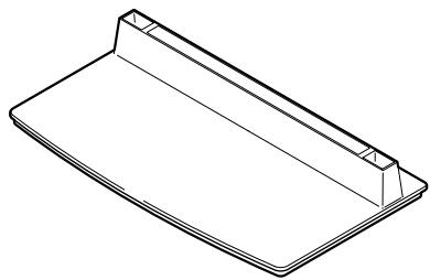
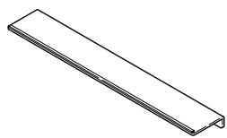
- Base cover x 1
natural_image
Isometric line drawing of a rectangular tray or shelf with no text or symbols-
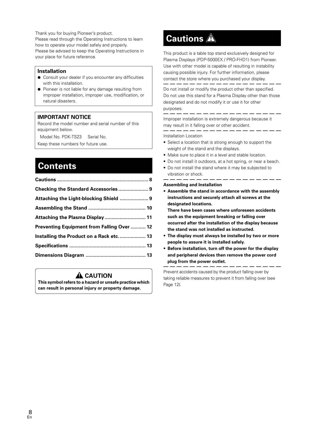
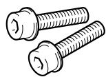
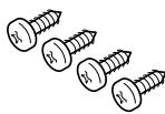
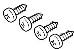
Screws (4 mm x 10 mm) x 4
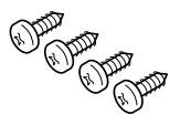
-
Installation bolts ① (M8 x 20 mm: black) x 2
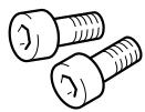
-
Stand pipes (left and right, interchangeable) x 2
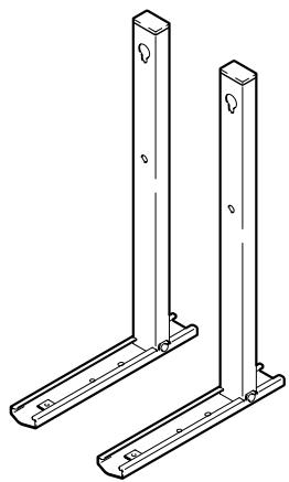
natural_image
Technical line drawing of two vertical metal supports with mounting holes (no text or symbols)- Installation bolts ②
(M8 x 40 mm: black) x 2
• Light-blocking shield x 1
-
Hexagonal wrench x 1 (Opposite side 6 mm for M8 use)
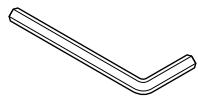
-
Operating instructions (this document) x 1

Attaching the Light-blocking Shield
This part prevents reflection of the cables connected to the back of the Plasma Display on the base cover.
Note
Attach it after anchoring the base cover on a flat stable place.
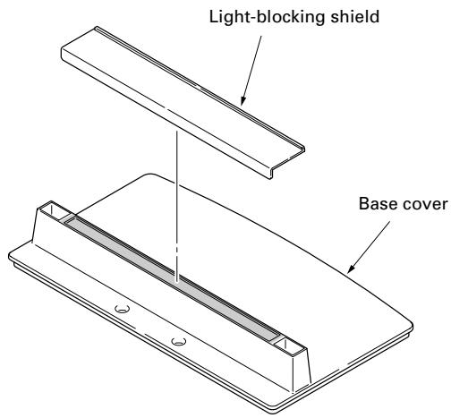
Attachment Procedure
1 Remove the double-sided adhesive tape from the light-blocking shield.
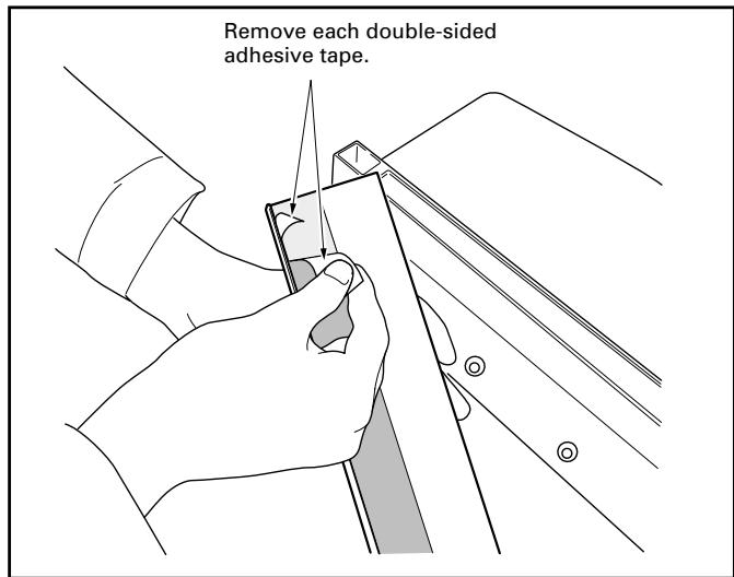
Attaching the Light-blocking Shield
2 While firmly holding the ends of the light-blocking shield, apply it with the double-sided adhesive tape.
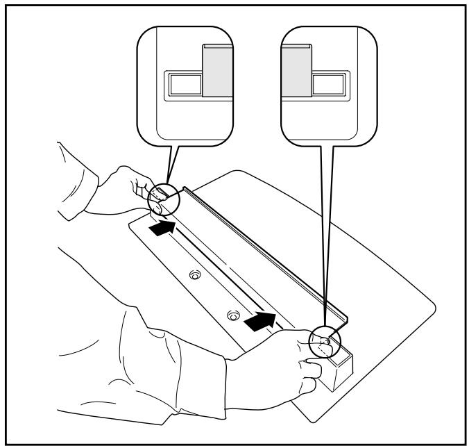
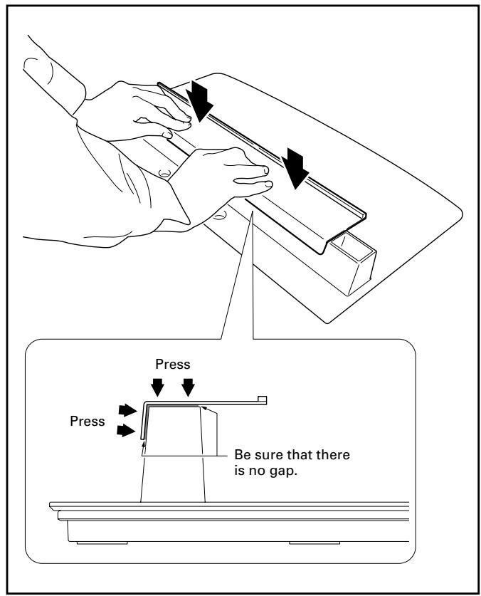
Note
- Be careful that the light-blocking shield does not catch on the pipe insertion holes.
- Anchor it in place so that there are no gaps (See diagram at right). If there is a gap, the light-blocking shield may peel off.
3 Anchor it in place while pressing it down from above.
Assembling the Stand
Assembly Procedure
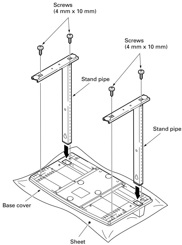
1 Turn the base cover over so the underside is facing up.
Note
When the base cover is turned over, be very careful not to scratch or damage the light-blocking shield.
2 Insert the stand pipes into the base cover.
3 Tighten the screws to stabilize the stand pipes.
Note
Assemble the stand with a soft sheet placed under the base cover.
If a sheet is not laid before assembly, the front surface of the base cover may be scratched.
Attaching the Plasma Display

Caution
The weight of a Plasma Display is about 40 kg (88 lbs), they have no depth, and are unstable. Therefore, at least two people must assemble and install them.
Note
- Insert the bolts in the holes vertically.
- Place a sheet or protective cover to protect the display from scratches or damage.
- Assemble only with the Plasma Display lying flat on a table or similar surface.
- Move the stand so that the stand screw holes and the nuts that connect the main display line up correctly.
1 With the Plasma Display lying flat, insert and secure the two Installation bolts ① (M8 x 20 mm: black) in the holes "a" located in center of the Plasma Display housing.
At this point, tighten these bolts ① only until the threads are no longer visible when viewed from the side (you will be unable to attach the display if the bolts are screwed in completely).
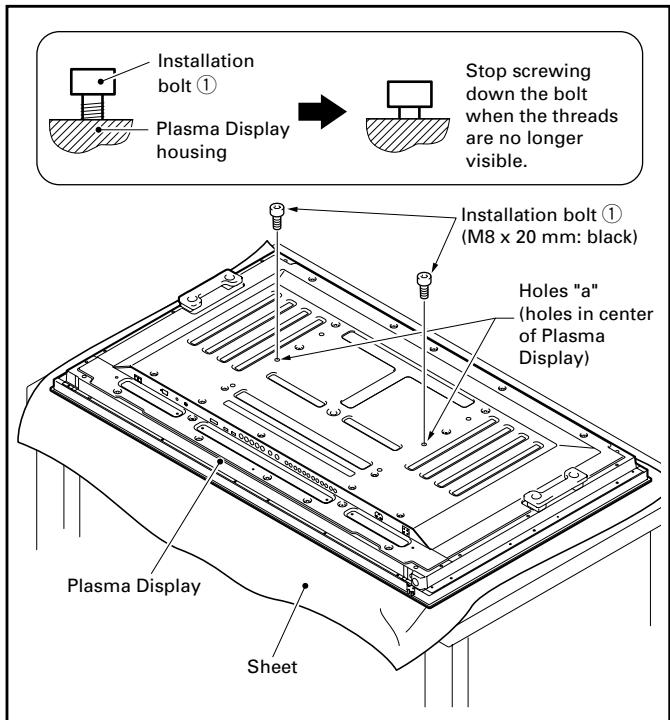
Note
When laying down the Plasma Display, be careful so as to not scratch or damage it.
■ Regarding the stand pipe screw holes when the stand is used as a desktop stand
Please use Ⓐ and Ⓐ' in the following diagram.
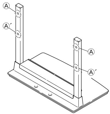
2 As shown in the above diagram, hook the stand pipe holes Ⓐ onto the screw heads of the installation bolts ①, then slide the stand upwards to the main Plasma Display until it engages the installation bolts ①.
3 Pass the installation bolts ② (M8 x 40 mm: black) through the stand pipe holes Ⓐ', and then screw them into the main Plasma Display with the accessory hexagonal wrench.
Be sure to tighten the bolts securely.
4 Tighten the installation bolts ① firmly with the accessory hexagonal wrench.
Be sure to tighten the bolts securely.
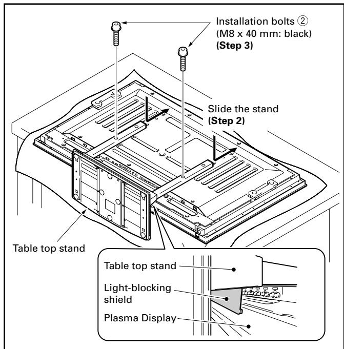
Note
- Attach the Plasma Display so the light-blocking shield touches the bottom of its back surface.
● To install it in a rack etc. see Page 13.
Preventing Equipment from Falling Over
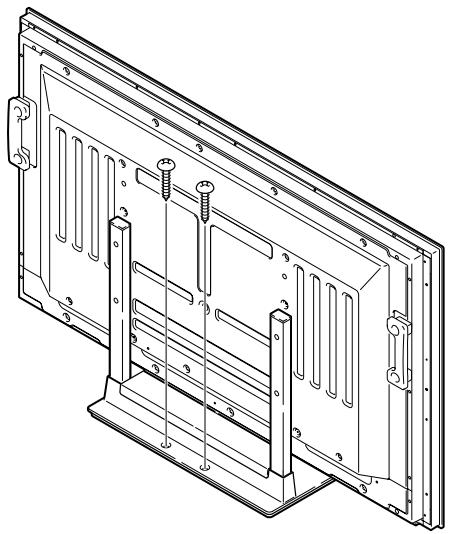
After installing the stand, be sure to take special care to ensure that the equipment will not fall over.
Stabilizing on table
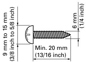
Stabilize the equipment as shown in the diagram using screws that are available on the market.
Note
To stabilize the equipment on a table, use screws that have a nominal diameter of 6 mm (1/4 inch) and that are at least 20 mm (13/16 inch) long.
natural_image
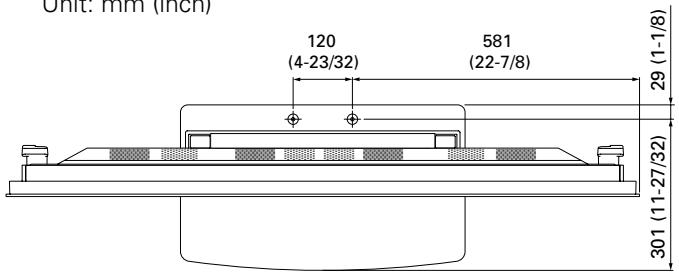
Technical line drawing of a mechanical frame assembly with mounting brackets and bolts (no text or symbols)◆ Position of screws
When stabilizing the stand to a table, use nominal diameter 6 mm (1/4 inch) with a length above 20 mm (13/16 inch).
Unit: mm (inch)
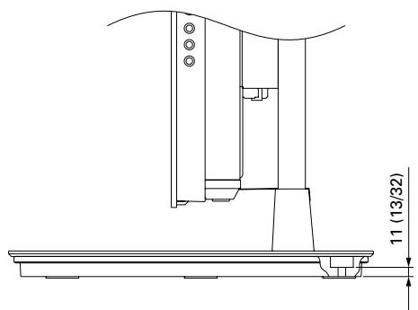
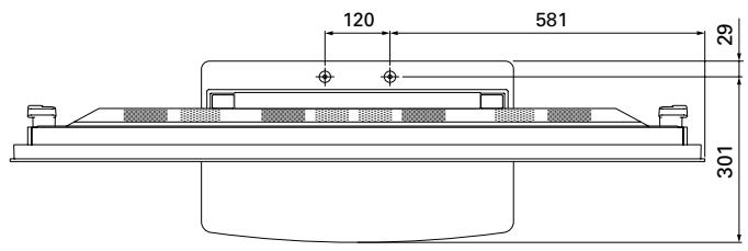
Side View
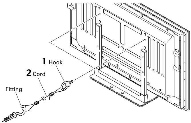
Using a wall for stabilization
1 Attaching falling prevention bolts (hooks) to the Plasma Display.
2 Using strong cords to firmly stabilize it appropriately and firmly to a wall, pillar, or other sturdy element.
Perform this work in the same way on the left and right sides.
Note
Use hooks, cords, and fittings that are available on the market.
Recommended hook:
Nominal diameter M8
Length 12 mm to 15 mm (1/2 inch to 5/8 inch)
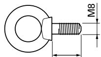
12 mm to 15 mm
(1/2 inch to 5/8 inch)

Caution
- A table or an area of the floor with adequate strength should always be used to support the Plasma Display.
Failure to do so could result in personal injury and physical damage. - When installing the Plasma Display, please take the necessary safety measures to prevent it from falling or overturning in case of emergencies, such as earthquakes, or of accidents.
- If you do not take these precautions, the Plasma Display could fall down and cause injury.
- The screws, hooks, chains and other fittings that you use to secure the Plasma Display to prevent it from overturning will vary according to the composition and thickness of the surface to which it will be attached.
- Select the appropriate screws, hooks, chains and other fittings after first inspecting the surface carefully to determine its thickness and composition and after consulting a professional installer if necessary.
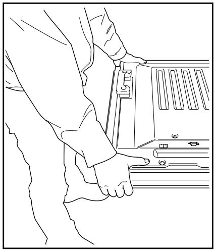
Installing the Product on a Rack etc.

Caution
When installing on a rack, etc., please be sure that the Plasma Display is held by two people.
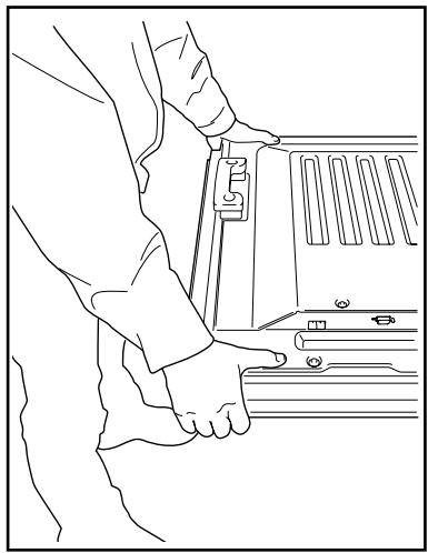
How to hold the Plasma Display
When holding the Plasma Display erect:
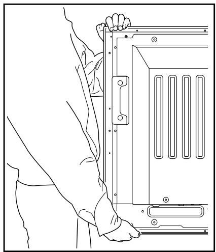
natural_image
Line drawing of a person installing or adjusting a mechanical component (no text or symbols present)When laying down the Plasma Display:

natural_image
Line drawing of a person adjusting a vehicle door panel (no text or symbols)Specifications
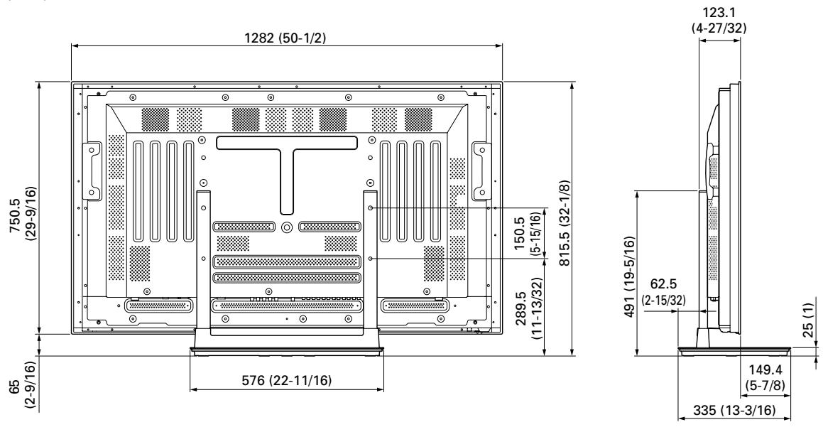
External dimensions 576 mm (W) x 491 mm (H) x 335 mm (D) (22-11/16 in. (W) x 19-5/16 in. (H) x 13-3/16 in. (D))
Weight 5.9 kg (13.0 lbs)
- The above specifications and exterior may be modified without prior notice to improve the product.
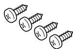
Dimensions Diagram
Unit: mm (inch)
Published by Pioneer Corporation. Copyright © 2006 Pioneer Corporation. All rights reserved.
natural_image
Isometric line drawing of a rectangular tray or shelf with a flat top and side edges (no text or symbols)natural_image
Technical line drawing of two metal support structures with mounting holes (no text or symbols)Remarque
natural_image
Technical line drawing of a metal enclosure frame with mounting brackets and bolts (no text or symbols)◆ Position des vis
natural_image
Technical line drawing of a mechanical assembly with a base plate and support structure (no text or symbols)Vue latérale
natural_image
Line drawing of a person installing or adjusting a mechanical component (no text or symbols present)natural_image
Line drawing of a person using a tool on a vehicle door panel (no text or symbols)Publication de Pioneer Corporation.
© 2006 Pioneer Corporation.
natural_image
Isometric line drawing of a rectangular tray or shelf with a flat top and side edges (no text or symbols)• Schrauben (4 mm x 10 mm) x 4
natural_image
Technical line drawing of two vertical metal supports with mounting holes (no text or symbols)Hinweis
natural_image
Technical line drawing of a metal enclosure frame with mounting brackets and bolts (no text or symbols)natural_image
Technical line drawing of a mechanical assembly with no visible text or symbolsSeitenansicht
natural_image
Line drawing of a person installing or adjusting a device panel (no text or symbols present)Halten beim
natural_image
Line drawing of a person adjusting a vehicle door panel (no text or symbols)Technische Daten
Model N. PDK-TS23 Serial No.
natural_image
Isometric line drawing of a rectangular tray or container with a flat top and side edges (no text or symbols)natural_image
Technical line drawing of two vertical metal supports with mounting holes (no text or symbols)Nota
natural_image
Technical line drawing of a mechanical enclosure or panel frame with mounting brackets and bolts (no text or symbols)natural_image
Technical line drawing of a mechanical assembly with a base plate and support structure (no text or symbols)Vista laterale
Fissare l'apparecchio al muro
natural_image
Line drawing of a person installing or adjusting a mechanical device panel (no text or symbols present)natural_image
Line drawing of a person adjusting a vehicle door panel (no text or symbols)Dati tecnici
Misure esterne 576 mm (L) x 491 mm (A) x 335 mm (P)
Peso 5,9 kg
Copyright © 2006 Pioneer Corporation.
natural_image
Isometric line drawing of a rectangular tray or container with a flat top and side edges (no text or symbols)• Schroeven (4 mm x 10 mm) x 4
natural_image
Technical line drawing of two metal frame structures with mounting holes (no text or symbols)Let op
natural_image
Technical line drawing of a metal enclosure frame with mounting brackets and bolts (no text or symbols)natural_image
Technical line drawing of a mechanical assembly with a base plate and support structure (no text or symbols)Zijaanzicht
natural_image
Line drawing of a person installing or adjusting a mechanical device panel (no text or symbols present)Zo legt u de plasma-
display neer:
natural_image
Line drawing of a person adjusting a device panel (no text or symbols)Technische gegevens
natural_image
Isometric line drawing of a rectangular tray or container with a flat top and side edges (no text or symbols)natural_image
Technical line drawing of two vertical metal supports with mounting holes (no text or symbols)Nota
natural_image
Technical line drawing of a metal enclosure with mounting brackets and structural ribs (no text or symbols)natural_image
Technical line drawing of a mechanical assembly with a base plate and support structure (no text or symbols)Vista lateral
natural_image
Line drawing of a person installing or adjusting a mechanical component (no text or symbols present)natural_image
Line drawing of a person adjusting a vehicle door panel (no text or symbols)Especificaciones
Dimensiones externas: 576 mm (ancho) x 491 mm (alto) x 335 mm (fondo)
Peso: 5,9 kg
Copyright © 2006 Pioneer Corporation.
natural_image
Isometric line drawing of a rectangular tray or shelf with a flat top and side edges (no text or symbols)natural_image
Technical line drawing of two vertical metal supports with mounting holes (no text or symbols)附註
natural_image
Technical line drawing of a mechanical assembly with a base plate and support structure (no text or symbols)側面
利用牆壁固定
natural_image
Line drawing of a person installing or adjusting a mechanical component (no text or symbols present)在放下電漿顯示器時:

natural_image
Line drawing of a person adjusting a vehicle door panel (no text or symbols)規格
AFTER-SALES SERVICE FOR PIONEER PRODUCTS
Please contact the dealer or distributor from where you purchased the product for its after-sales service (including warranty conditions) or any other information. In case the necessary information is not available, please contact the Pioneer's subsidiaries (regional service headquarters) listed below:
PLEASE DO NOT SHIP YOUR PRODUCT TO THE COMPANIES at the addresses listed below for repair without advance contact, for these companies are not repair locations.
AMERICA
PIONEER ELECTRONICS (USA) INC.
CUSTOMER SUPPORT DIVISION
P.O. BOX 1760, LONG BEACH, CA 90801-1760, U.S.A.
CUSTOMER SERVICE HOTLINE : (800) 421-1404
EUROPE
PIONEER EUROPE NV
EUROPEAN SERVICE DIVISION
HAVEN 1087, KEETBERGLAAN 1, B-9120 MELSELE, BELGIUM
ASEAN
PIONEER ELECTRONICS ASIACENTRE PTE. LTD.
SERVICE DEPARTMENT
253, ALEXANDRA ROAD #04-01 SINGAPORE 159936
JAPAN AND OTHERS
PIONEER CORPORATION (HEAD OFFICE)
CUSTOMER SUPPORT CENTER
Printed on recycled paper.
Published by Pioneer Corporation.
Copyright © 2006 Pioneer Corporation.
All rights reserved.
パイオニア株式会社
PIONEER ELECTRONICS (USA) INC.
P.O. BOX 1540, Long Beach, California 90810-1540, U.S.A. TEL: (800) 421-1404
PIONEER ELECTRONICS OF CANADA, INC.
300 Allstate Parkway, Markham, Ontario L3R OP2, Canada TEL: 1-877-283-5901
PIONEER EUROPE NV
Haven 1087, Keetberglaan 1, B-9120 Melsele, Belgium TEL: 03/570.05.11
PIONEER ELECTRONICS ASIACENTRE PTE. LTD.
253 Alexandra Road, #04-01, Singapore 159936 TEL: 65-6472-7555
PIONEER ELECTRONICS AUSTRALIA PTY. LTD.
178-184 Boundary Road, Braeside, Victoria 3195, Australia, TEL: (03) 9586-6300
PIONEER ELECTRONICS DE MEXICO S.A. DE C.V.
Blvd.Manuel Avila Camacho 138 10 piso Col.Lomas de Chapultepec, Mexico,D.F. 11000 TEL: 55-9178-4270


- ご注意
- 壁を利用する方法
- 仕様
- Installation
- IMPORTANT NOTICE
- Contents
- CAUTION
- Cautions
- Assembling and Installation
- Checking the Standard Accessories
- Attaching the Light-blocking Shield
- Note
- Attachment Procedure
- Assembling the Stand
- Assembly Procedure
- Attaching the Plasma Display
- With the Plasma Display lying flat, insert and secure the two Installation bolts ① (M8 x 20 mm: black) in the holes "a" located in center of the Plasma Display housing.
- ■ Regarding the stand pipe screw holes when the stand is used as a desktop stand
- Tighten the installation bolts ① firmly with the accessory hexagonal wrench.
- Preventing Equipment from Falling Over
- Stabilizing on table
- ◆ Position of screws
- Using a wall for stabilization
- Installing the Product on a Rack etc.
- How to hold the Plasma Display
- Specifications
- Dimensions Diagram
- Remarque
- ◆ Position des vis
- Hinweis
- Technische Daten
- Nota
- Fissare l'apparecchio al muro
- Dati tecnici
- Let op
- Technische gegevens
- Especificaciones
- 附註
- 利用牆壁固定
- 規格
- AFTER-SALES SERVICE FOR PIONEER PRODUCTS
- AMERICA
- EUROPE
- ASEAN
- JAPAN AND OTHERS
- パイオニア株式会社
Brand : PIONEER
Model : PDK-TS23
Category : Media player