PBASR-M8-D45 - Barbecue ASROCK - Free user manual and instructions
Find the device manual for free PBASR-M8-D45 ASROCK in PDF.

User questions about PBASR-M8-D45 ASROCK
0 question about this device. Answer the ones you know or ask your own.
Ask a new question about this device
Download the instructions for your Barbecue in PDF format for free! Find your manual PBASR-M8-D45 - ASROCK and take your electronic device back in hand. On this page are published all the documents necessary for the use of your device. PBASR-M8-D45 by ASROCK.
USER MANUAL PBASR-M8-D45 ASROCK
natural_image
Exterior view of a black ASRock device with red hexagonal lens and control panel (no readable text or symbols)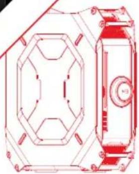
natural_image
Technical line drawing of a mechanical component with hexagonal and circular features (no text or symbols)User Manual

natural_image
Abstract geometric logo design with stylized letter M and red/gray lines (no text or symbols)Version 1.0
Published August 2013
Copyright©2013 ASRock Inc. All rights reserved.
Copyright Notice:

text_image
QR code image containing encoded data, no visible human-readable textNo part of this documentation may be reproduced, transcribed, transmitted, or translated in any language, in any form or by any means, except duplication of documentation by the purchaser for backup purpose, without written consent of ASRock Inc.
Products and corporate names appearing in this documentation may or may not be registered trademarks or copyrights of their respective companies, and are used only for identification or explanation and to the owners' benefit, without intent to infringe.
Disclaimer:
Specifications and information contained in this documentation are furnished for informational use only and subject to change without notice, and should not be constructed as a commitment by ASRock. ASRock assumes no responsibility for any errors or omissions that may appear in this documentation.
With respect to the contents of this documentation, ASRock does not provide warranty of any kind, either expressed or implied, including but not limited to the implied warranties or conditions of merchantability or fitness for a particular purpose.
In no event shall ASRock, its directors, officers, employees, or agents be liable for any indirect, special, incidental, or consequential damages (including damages for loss of profits, loss of business, loss of data, interruption of business and the like), even if ASRock has been advised of the possibility of such damages arising from any defect or error in the documentation or product.

This device complies with Part 15 of the FCC Rules. Operation is subject to the following two conditions:
(1) this device may not cause harmful interference, and
(2) this device must accept any interference received, including interference that may cause undesired operation.
CALIFORNIA, USA ONLY
The Lithium battery adopted on this motherboard contains Perchlorate, a toxic substance controlled in Perchlorate Best Management Practices (BMP) regulations passed by the California Legislature. When you discard the Lithium battery in California, USA, please follow the related regulations in advance.
"Perchlorate Material-special handling may apply, see www.dtsc.ca.gov/hazardouswaste/perchlorate"
Website: http://www.asrock.com
Important Safety Instructions
Pay close attention to the following safety instructions before performing any of the operation. Basic safety precautions should be followed to protect yourself from harm and the product from damage:
- Operation of the product should be carried out by suitably trained, qualified, and certified personnel only to avoid risk of injury from electrical shock or energy hazard.
- Disconnect the power cord from the wall outlet when installing or removing main system components, such as the motherboard and power supply unit.
- Place the system on a stable and flat surface.
- Use extreme caution when working with high-voltage components.
- When handling parts, use a grounded wrist strap designed to prevent static discharge.
- Keep the area around the system clean and clutter-free.
- Keep all components and printed circuit boards (PCBs) in their antistatic bags when not in use.
- Handle a board by its edges only; do not touch its components, peripheral chips, memory modules or contacts.
Contact Information
If you need to contact ASRock or want to know more about ASRock, you're welcome to visit ASRock's website at http://www.asrock.com; or you may contact your dealer for further information. For technical questions, please submit a support request form at http://www.asrock.com/support/tsd.asp
ASRock Incorporation
2F., No.37, Sec. 2, Jhongyang S. Rd., Beitou District,
Taipei City 112, Taiwan (R.O.C.)
ASRock EUROPE B.V.
Bijsterhuizen 3151
6604 LV Wijchen
The Netherlands
Phone: +31-24-345-44-33
Fax: +31-24-345-44-38
ASRock America, Inc.
13848 Magnolia Ave, Chino, CA91710
U.S.A.
Phone: +1-909-590-8308
Fax: +1-909-590-1026
Chapter 1 Introduction
Thank you for purchasing M8, a reliable gaming barebone system produced under ASRock's consistently stringent quality control. It delivers excellent performance with robust design conforming to ASRock's commitment to quality and endurance.

Because the hardware specifications might be updated, the content of this documentation will be subject to change without notice. In case any modifications of this documentation occur, the updated version will be available on ASRock's website without further notice. If you require technical support related to this product, please visit our website for specific information about the model you are using. ASRock website: http://www.asrock.com.
1.1 Package Contents
- M8 Barebone System with: M8 Chassis Mini-ITX Motherboard (pre-installed) Power Supply Unit (pre-installed) System Fan (pre-installed)
- AC Power Cable
- Hexagon Screwdriver
- Screwdriver Set
- Screw Package
- System Key
- VGA Support
- 6 x SATA Cable
- Support CD
- Quick Installation Guide
- User Manual

If any items are missing or appear damaged, contact your authorized dealer.
1.2 Product Specifications
| Color | • Storm Black |
| Material | • Steel Body / Aluminum + Plastic |
| Dimension | • 372mm (W) x 123mm (H) x 400mm (L) |
| Motherboard | • ASRock Z87-M8 |
| CPU | • Supports 4^th Gen Intel ^ Core ^TM i7 / i5 / i3 / Xeon ^ / Pentium ^ / Celeron ^ Processor Family |
| Memory | • Supports DDR3 1600/1333/1066 MHz, 2 x SO-DIMM slots, Max. up to 16GB |
| VGA | • Supports 1 x Dual-slot Graphics Card* |
| Optical Drive | • 1 x Slim Slot-in Super-Multi Drive |
| Hard Disk | • Supports 3.5"HDD and 2.5"HDD |
| WiFi + BT | • 2T2R WiFi 802.11ac + BT v4.0 |
| Front I/O | • 4 x USB 3.0, 1 x MIC, 1 x Headphone• 4-in-1 Card reader (SD3.0/MMC/MS/MS PRO) |
| Rear I/O | • 1 x 7.1HD audio with Creative Sound Core3D,• 1 x Intel Gigabit LAN, 4 x USB3.0, 4 x USB2.0,• 1 x eSATA2, 1 x DP, 1 x HDMI |
| All-In-One OLED Button | • A-Command |
| Cooling | • Top : 2 x 70mm fan, Bottom : 2 x 70mm fan |
| Power Supply | • SFX PSU 450W |
* Max. Supported VGA Dimension: 290mm x 137mm x 43.5mm; Max. Supported TDP: 200W
(If you use a graphics card with over 200W TDP, please note that the system's power supply is only 450W.)
1.3 Unique Features

ASRock A-Tuning
A-Tuning is ASRock's multi purpose software suite with a new interface, more new features and improved utilities, including XFast RAM, Dehumidifier, Good Night LED, FAN-Tastic Tuning, OC Tweaker and a whole lot more.

ASRock Instant Flash
ASRock Instant Flash is a BIOS flash utility embedded in Flash ROM. This convenient BIOS update tool allows you to update the system BIOS in a few clicks without preparing an additional floppy diskette or other complicated flash utility. Just save the new BIOS file to your USB storage and launch this tool by pressing

ASRock APP Charger
Simply by installing the ASRock APP Charger makes your iPhone/iPad/iPod Touch charge up to 40% faster than before on your computer. ASRock APP Charger allows you to quickly charge many Apple devices simultaneously and even supports continuous charging when your PC enters into Standby mode (S1), Suspend to RAM (S3), hibernation mode (S4) or power off (S5).

ASRock XFast USB
ASRock XFast USB can boost the performance of your USB storage devices. The performance may depend on the properties of the device.

ASRock XFast LAN
ASRock XFast LAN provides faster internet access, which includes the benefits listed below. LAN Application Prioritization: You can configure your application's priority ideally and add new programs to the list. Lower Latency in Game: After setting online game's priority higher, it can lower the latency in games. Traffic Shaping: You can watch Youtube HD videos and download simultaneously. Real-Time Analysis of Your Data: With the status window, you can easily recognize which data streams you are currently transferring.

ASRock XFast RAM
ASRock XFast RAM is included in A-Tuning. It fully utilizes the memory space that cannot be used under Windows® 32-bit operating systems. ASRock XFast RAM shortens the loading time of previously visited websites, making web surfing faster than ever. And it also boosts the speed of Adobe Photoshop 5 times faster. Another advantage of ASRock XFast RAM is that it reduces the frequency of accessing your SSDs or HDDs in order to extend their lifespan.

ASRock X-FAN
Greater air flow, faster heat dissipation! ASRock X-FAN allows the motherboard to breathe smoothly. It will be automatically activated only when the system rises to a certain temperature under heavy-loading. Normally, ASRock X-FAN will remain deactivated to give users the quietest computing experience

ASRock Crashless BIOS
ASRock Crashless BIOS allows users to update their BIOS without fear of failing. If power loss occurs during the BIOS updating process, ASRock Crashless BIOS will automatically finish the BIOS update procedure after regaining power. Please note that BIOS files need to be placed in the root directory of your USB disk. Only USB 2.0 ports support this feature.

ASRock OMG (Online Management Guard)
Administrators are able to establish an internet curfew or restrict internet access at specified times via OMG. You may schedule the starting and ending hours of internet access granted to other users. In order to prevent users from bypassing OMG, guest accounts without permission to modify the system time are required.

ASRock Internet Flash
ASRock Internet Flash downloads and updates the latest UEFI firmware version from our servers for you without entering Windows OS. Please setup network configuration before using Internet Flash.

ASRock UEFI System Browser
ASRock System Browser shows the overview of your current PC and the devices connected.

ASRock Dehumidifier Function
Users may prevent motherboard damages due to dampness by enabling "Dehumidifier Function". When enabling Dehumidifier Function, the computer will power on automatically to dehumidify the system after entering S4/S5 state.

ASRock Interactive UEFI
ASRock Interactive UEFI is a blend of system configuration tools, cool sound effects and stunning visuals. The unprecedented UEFI provides a more attractive interface and more amusement.

ASRock Fast Boot
With ASRock's exclusive Fast Boot technology, it takes less than 1.5 seconds to logon to Windows 8 from a cold boot. No more waiting! The speedy boot will completely change your user experience and behavior.

ASRock Restart to UEFI
Windows ^® 8 brings the ultimate boot up experience. The lightning boot up speed makes it hard to access the UEFI setup. ASRock Restart to UEFI allows users to enter the UEFI automatically when turning on the PC. By enabling this function, the PC will enter the UEFI directly after you restart.

ASRock Good Night LED
ASRock Good Night LED technology offers you a better sleeping environment by extinguishing the unessential LEDs. By enabling Good Night LED in the BIOS, the Power/HDD LEDs will be switched off when the system is powered on. Good Night LED will automatically switch off the Power and Keyboard LEDs when the system enters into Standby/Hibernation mode as well.

ASRock USB Key
In a world where time is money, why waste precious time everyday typing usernames to log in to Windows? Why should we even bother memorizing those foot long passwords? Just plug in the USB Key and let your computer log in to windows automatically!

ASRock Key Master
What good is a weapon if you are unable to wield it proficiently? Key Master enhances your mouse and keyboard with customizable macros, sniper modes, scroll speed, key repeat rates and repeat delay, turning your boring old keyboard and mouse into lethal weapons.
ASRock FAN-Tastic Tuning
ASRock FAN-Tastic Tuning is included in A-Tuning. Configure up to five different fan speeds using the graph. The fans will automatically shift to the next speed level when the assigned temperature is met.


ASRock Easy Driver Installer
For users that don't have an optical disk drive to install the drivers from our support CD, Easy Driver Installer is a handy tool in the UEFI that installs the LAN driver to your system via an USB storage device, then downloads and installs the other required drivers automatically.
Chapter 2 Product Overview
This chapter provides diagrams showing the location of important components of the M8.
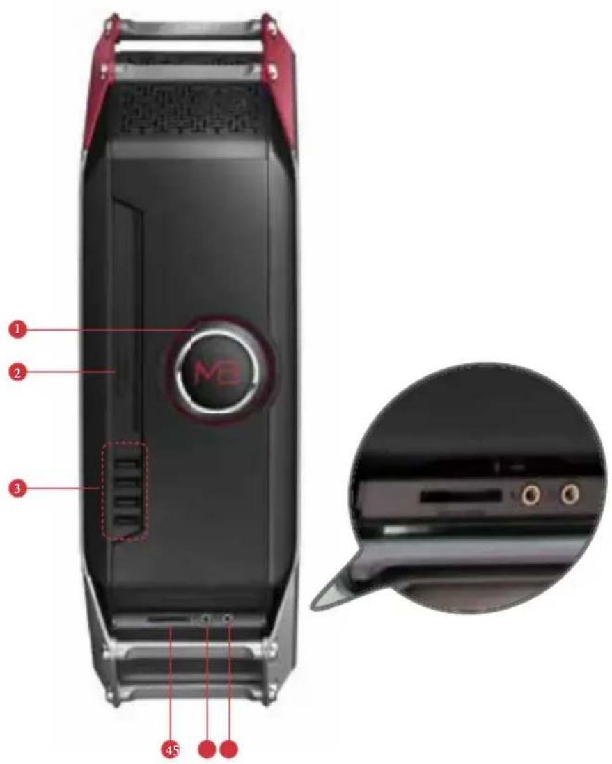
2.1 Front View
text_image
Diagram of a black device with labeled parts and an inset close-up showing internal components.No. Description
1 A-Command (All-In-One OLED Button)
2 Optical disk drive eject button
3 4 x USB 3.0 ports
4 4-in-1 Card reader (SD3.0/MMC/MS/MS PRO)
5 Microphone jack
6 Headphone jack
2.1.1 The Function of A-Command
The A-Command is a multipurpose controller knob which is used to cycle through various functions.

text_image
MBControlling A-Command
- Rotate the knob to toggle among main functions or options.
• Press once to confirm your selection.
Powering on the System
Press A-Command to turn on the system power. Wait until the operating system loads automatically.
Powering off the System
When the OLED shows the M8 Logo / Date and Time, press A-Command and select "Yes" to turn off the system power.
Before Entering Windows
There are three main functions before entering the OS.
- M8 Logo / Date and Time:
After the logo appears for ten seconds, the screen shows date and time. The display will go off if you leave it idle for five minutes.
• Light: Toggle on/off the light in the case. - Time: Toggle the time on/off. If this option is set to on, M8 Logo / Date and Time screens are available. If this option is set to off, M8 Logo / Date and Time screens are hidden.
Under Windows:
There are six main functions after entering the OS.
• M8 Logo / Date and Time:
After the logo appears for ten seconds, the screen shows date and time.
The display will go off if you leave it idle for five minutes.
• Volume:
Increase/decrease the volume level by turning the knob right/left.
- Mode:
Toogle among three power management modes - Eco, Standard or Speed.
- Info:
Toggle among various types of critical information to check the system's status. The OLED screen shows the CPU frequency, CPU usage, LAN usage, or APM* data.
*APM (Actions per minute) measures the number of keyboard/mouse-clicking action that you can perform in a minute. To find out how fast your fingers can move, press A-Command once to start counting APM. Press A-Command once again to stop it.
• Light:
Toggle on/off the light in the case, or enable the Good Night LED function*.
On: Toggle on the light in the case
Off: Toggle off the light in the case
All off: Toggle off the light in the case; enable the Good Night LED function
*ASRock Good Night LED technology offers you a better sleeping environment by extinguishing the unessential LEDs. By enabling Good Night LED, the
Power/HDD LEDs will be switched off when the system is powered on. Good Night LED will automatically switch off the Power and Keyboard LEDs when the system enters into Standby/Hibernation mode as well.
- Time:
Toggle the time on/off.
If this option is set to on, M8 Logo / Date and Time screens are available. If this option is set to off, M8 Logo / Date and Time screens are hidden.
2.2 Rear View

text_image
Back panel diagram of a server rack with labeled ports and connectors, marked with red annotations 12 and 3.No. Description
1 PCIe slot covers
2 I/O panel
3 AC input power connector
2.2.1 I/O Panel

text_image
MB in out mic sub rear S/PDIF USB 3.0 USB 3.0 DISPLAY PORT HDMI USB 2.0 eSATA USB 2.0 1 2 3 4 5 6 7 18 17 15 16 13 14 11 12 10 8 9No. Description No. Description
1 Line In port (light blue) 10 eSATA2 port**
2 Line Out port (lime) 11 DisplayPort
3 Center/Subwoofer port (orange)
12 HDMI port
4 Rear Speaker Out port (black) 13 USB3.0 port
5 LAN RJ-45 port* (Intel Gigabit LAN) 14 USB3.0 port
6 USB2.0 ports 15 USB3.0 port
7 USB2.0 ports 16 USB3.0 port
8 USB2.0 ports 17 Optical SPDIF Out port
9 USB2.0 ports 18 Microphone port (pink)
* There are two LEDs on the LAN port. Please refer to the table below for the LAN port LED indications.

text_image
SPEED LED ACT/LINK LED LAN PortActivity / Link LED Speed LED
| Status | Description | Status | Description |
| Off | No Link | Off | 10Mbps connection |
| Blinking | Data Activity | Orange | 100Mbps connection |
| On | Link | Green | 1Gbps connection |
** The eSATA connector is shared with SATA3_4 connector.
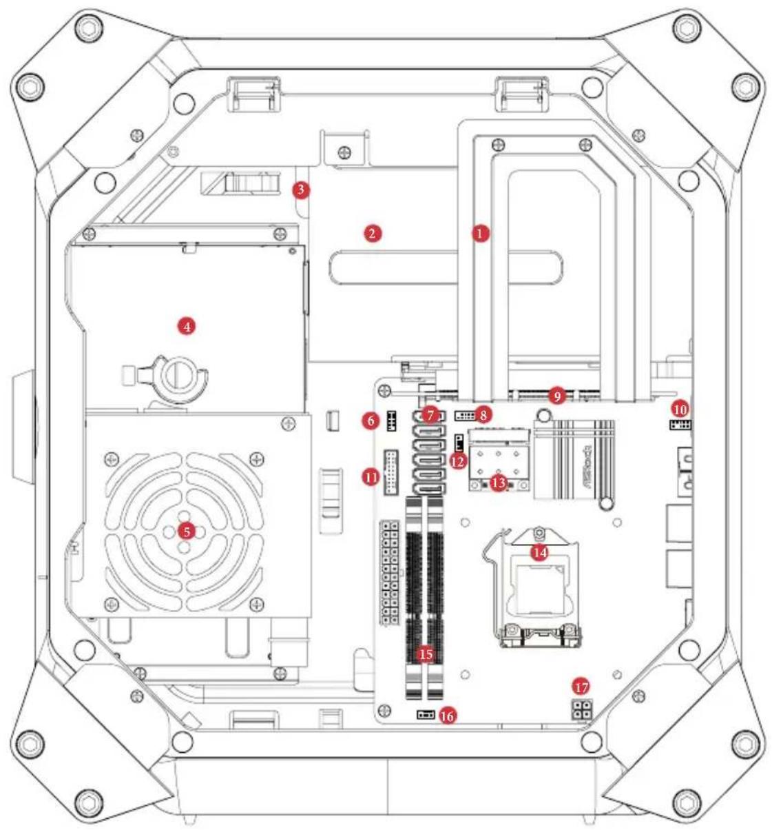
2.3 Inside View
text_image
Technical diagram of an electronic device rear panel with numbered components for identificationNo. Description
| 1 Riser card retention bracket | |
| 2 VGA card holder | |
| 3 Hard disk drive tray (compatible with 4 x 2.5" HDD or 1 x 3.5 HDD) | |
| 4 ODD + 2.5" HDD Tray | |
| (compatible with 1 x slot-in ODD and 1 x 2.5" HDD) | |
| 5 Power supply unit (450W) | |
| 6 Power panel connector | |
| 7 SATA 3.0 connectors | |
| 8 USB2.0 connector | |
| 9 PCIe slot | |
| 10 Front audio connector | |
| 11 USB3.0 connector | |
| 12 Auxiliary fan connector | |
| 13 2T2R WiFi Module (802.11ac) | |
| 14 CPU socket | |
| 15 DIMM sockets | |
| 16 Chassis fan connector | |
| 17 ATX 12V power connector | |

Hard drives are not included with this system.
Chapter 3 Hardware Installation
This chapter helps you assemble the chassis and install components. Please follow the installation procedures listed below.
Installation Procedures
1 Removing the side panels
2 Removing the top cover
3 Removing the VGA card holder
4 Removing the riser card
5 Installing the hard drives
6 Installing the CPU
7 Installing the CPU Fan and CPU Cooler
8 Installing Memory Modules (SO-DIMM)
9 Replace the riser card
10 Installing the graphics card
11 Replace the VGA card holder
12 Replacing the side panels
13 Replacing the top cover
After making sure that you have properly connected the power supply and all the necessary peripherals, power on the system.
3.1 Installing System Components
3.1.1 Removing the Side Panels

To remove the side panels, you have to unlock the keylock on the top cover using the system key. Before unlocking, power off the system and unplug the power cord. After the side panel are replaced, make sure to lock the keylock on the top cover and then power on the system.
- Place the system in an upright position.
- Unlock the system keylock on the top cover.

natural_image
Technical line drawing of a mechanical component with internal grid structure and mounting brackets (no text or symbols)- Remove the side panels.

text_image
Technical diagram of a device rear panel with labeled components and directional arrows indicating assembly or connection points.1 Pull the right side panel away from the chassis.
2 Pull the left side panel away from the chassis.
3.1.2 Removing the Top Cover

- To remove the top cover, you have to follow the procedures below:
1) Power off the system and unplug the power cord.
2) Unlock the keylock on the top cover using the system key.
3) Follow the instructions in Section 3.1 to remove the right side panel.
4) Slide the top cover toward the front of the system until it releases from the latch.
-
After the top cover is replaced, make sure to lock the keylock on the top cover and then power on the system.
-
The system must be operated with the chassis top cover installed to ensure proper cooling.

Remove the top cover to add graphics card or install hard drives.
- Place the system in an upright position.
- Unlock the system keylock on the top cover.
natural_image
Technical line drawing of a mechanical component with internal structure and mounting brackets (no text or symbols)- Follow the instructions in Section 3.1 to remove the right side panel.
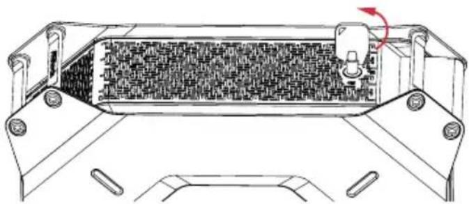
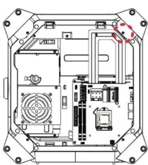
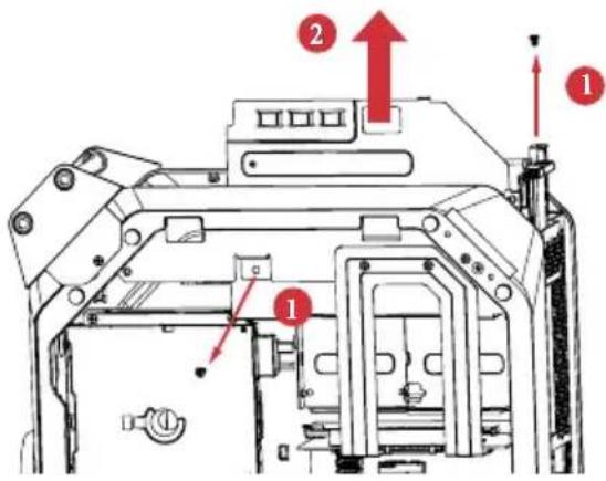
- Remove the one screw and two hexagon nuts that secure the top right bracket ear to the top cover.
natural_image
Technical line drawing of an internal electronic device casing with visible circuitry and components (no text or symbols)
natural_image
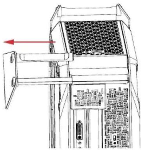
Technical line drawing of an electronic component with internal circuitry and mounting holes (no text or symbols)- Draw out the mounting bracket from the chassis.
natural_image
Technical line drawing of a mechanical device with internal components and a red directional arrow (no text or symbols)-
Follow the instructions in Section 3.1 to release the left side panel.
-
Release the top cover.
text_image
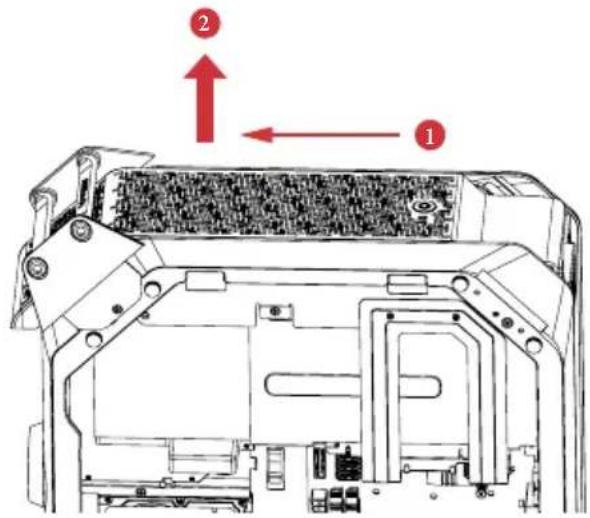
Technical diagram of a device interior with numbered annotations indicating directional movement or assembly points.1 Slide the top cover toward the front of the system until it releases.
2 Lift up the top cover.
- Disconnect the 4-pin top fan connector.
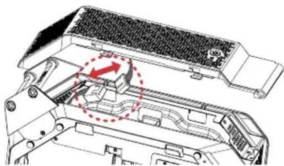
natural_image
Technical diagram of a mechanical assembly with no visible text or symbols- Set the top cover aside in a secure location.
3.1.3 Removing the VGA Card Holder

To remove the VGA card holder, you have to remove the side panels and top cover, giving you access to the VGA card holder inside.
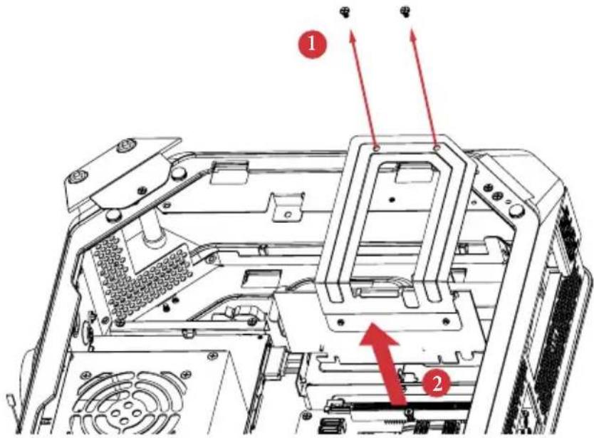
- Remove the VGA card holder.
text_image
Technical diagram of a mechanical assembly with numbered components and directional arrows indicating motion or assembly.1 Remove the two screws that hold the VGA card holder in place.
2 Lift the VGA card holder up and off the chassis.
3.1.4 Removing the Riser Card
- Remove the riser card.
text_image
Technical diagram of a computer chassis with numbered annotations indicating component locations1 Remove the two screws securing the riser card retention bracket.
2 Grasp the riser card by its edges, and carefully pull it from the expansion slot.
3.1.5 Installing the Hard Drives
3.1.5.1 Installing the Hard Drive(s) to the Drive Tray Assembly

- To install the hard drives, you have to remove the VGA card holder and the riser card, giving you access to the drive tray assembly inside.
- The drive tray assembly supports up to four 2.5-inch hard drives. You can also choose to install one 3.5-inch hard drive.
-
Hard drives are not included with this system.
-
Remove the drive tray assembly.
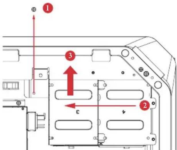
text_image
Technical diagram of a device rear panel with numbered components and directional arrows indicating movement or assembly.1 Remove the screw that secures the drive tray assembly to the chassis.
2 Slide the drive tray assembly toward the front of the system to disengage it from the latches.
3 Lift it away from the chassis.
- Take apart the drive tray assembly.

text_image
Technical diagram of a computer chassis with numbered components and red directional arrows indicating assembly or movement.1 Remove the screws that secure the bottom HDD tray with the top tray.
2 Take the assembly apart.
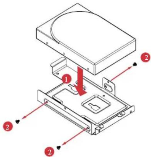
- Install a 3.5" HDD or up to four 2.5" HDD.
Installing a 3.5-Inch Hard Drive:
text_image
Technical diagram of an electronic device with labeled components and directional arrows indicating assembly or movement.1 Set the top tray aside.
Place a 3.5" HDD to the bottom HDD tray with the printed circuit board side facing down. Carefully align the mounting holes in the hard drive and the tray.
2 Secure the hard drive using the three screws (three on the sides).
Installing up to Four 2.5-Inch Hard Drive

text_image
Technical diagram of a hard disk drive assembly with numbered components and directional arrows indicating assembly steps.1 Place the first 2.5" HDD to the bottom HDD tray and secure the hard drive using the four screws (two on the sides and two in the rear).
2 Place the second 2.5" HDD to the top HDD tray and secure the hard drive using the four screws.
3 Secure the third HDD to the top HDD tray.
4 Secure the fourth HDD to the top HDD tray.
5 Attach the top HDD tray to the bottom HDD tray using four screws.
- Place the drive tray back into the chassis.
Slide the drive tray toward the rear of the system until the latches lock it into place.
-
Install and tighten the screw that secures the drive tray assembly to the chassis.
-
Connect the power and SATA data cables.
3.1.5.2 Installing the Hard Drive to the ODD + 2.5" HDD Tray

- To install the hard drives, you have to remove the PSU.
- The ODD + 2.5" HDD Tray fits a slim slot-in optical disk drive (ODD) and a 2.5-inch hard drives.
- Hard drives are not included with this system.
Installing a 2.5-Inch Hard Drive
1. Remove the PSU.
text_image
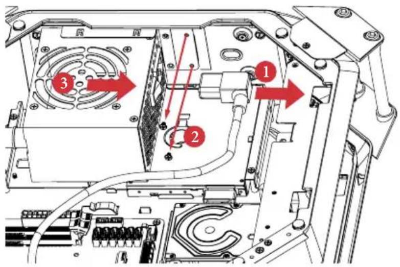
Technical diagram of an electronic device showing labeled components and directional arrows indicating assembly or movement.1 Unplug the PSU power cable.
2 Remove the two screws securing the power supply unit.
3 Slide the PSU to the right until it releases. Lift the PSU and set it aside.
- Remove the ODD+2.5" HDD Tray.

text_image
Technical diagram of an electronic device interior with numbered components and red directional arrows indicating flow or movement.1 Unplug the ODD SATA power connector.
2 Remove the five screws securing the ODD + 2.5" HDD Tray to the chassis.
3 Lift the tray off the chassis.
- Place a 2.5" HDD to the HDD tray and secure the hard drive using the four screws (four in the rear).

natural_image
Technical line drawing of a hard disk drive assembly with mounting holes and internal components (no text or symbols)- Align the screw holes on the ODD + 2.5" HDD Tray with the screw holes on the chassis. Fasten the five screws.
- Connect the power and SATA data cables and the ODD SATA power connector.
- Re-install the PSU.
text_image
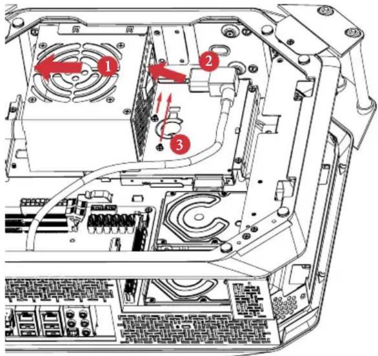
Technical diagram of an electronic device showing labeled components and wiring, with numbered annotations indicating parts 1, 2, and 3.1 Align the PSU with the starting line and then slide the PSU to the left until it reaches the end line. Make sure that it clicks into place.
2 Re-plug the PSU power cable.
3 Secure the two screws securing the power supply unit.
3.1.6 Replacing the ODD
- Follow the instructions in section 3.1.5.2 to remove the power supply unit and lift the tray off the chassis.
- Remove the old optical disk drive.
- Slide a new optical disk drive into the ODD tray.
- Attach the optical disk drive to the ODD tray using screws.
- Connect the ODD SATA power connector.
- Follow the instructions in section 3.1.5.2 to replace the ODD + 2.5" HDD Tray and the power supply unit.
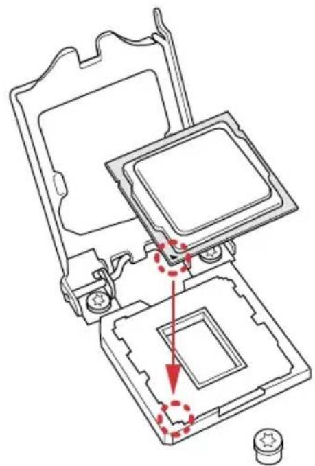
3.1.7 Installing the CPU

-
Before you insert the 1150-Pin CPU into the socket, please check if the PnP cap is on the socket, if the CPU surface is unclean, or if there are any bent pins in the socket. Do not force to insert the CPU into the socket if above situation is found. Otherwise, the CPU will be seriously damaged.
-
Unplug all power cables before installing the CPU.

text_image
1 A B C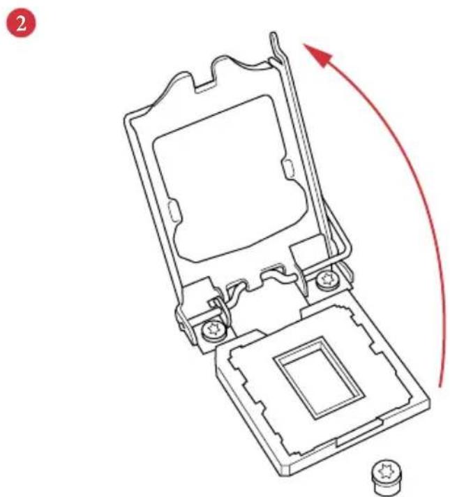
natural_image
Technical line drawing of a mechanical device with a red curved arrow indicating rotation or movement (no text or symbols present)3
natural_image
Technical line drawing of a mechanical assembly with no visible text or symbols4

natural_image
Line drawing of a computer processor with a red curved arrow indicating motion (no text or symbols)
Please save and replace the cover if the processor is removed. The cover must be placed if you wish to return the motherboard for after service.
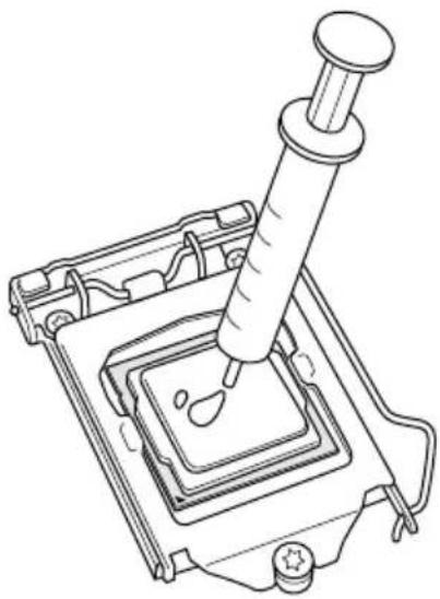
3.1.8 Installing the CPU Fan and CPU Cooler
natural_image
Line drawing of a mechanical device with a pipette inserted into a square component (no text or symbols)
text_image
Technical diagram showing installation of a CPU fan with cooling mechanism and component assembly, labeled with red arrows indicating motion.
text_image
2 C-05E+1
- Make sure to evenly spread the thermal paste over the CPU to improve heat dissipation.
- Ensure that the CPU and the CPU cooler are securely fastened and in good contact with each other.
- To make sure the CPU cooler is seated properly, it is highly recommended to check whether or not the CPU temperature reported in the BIOS is at a normal level.
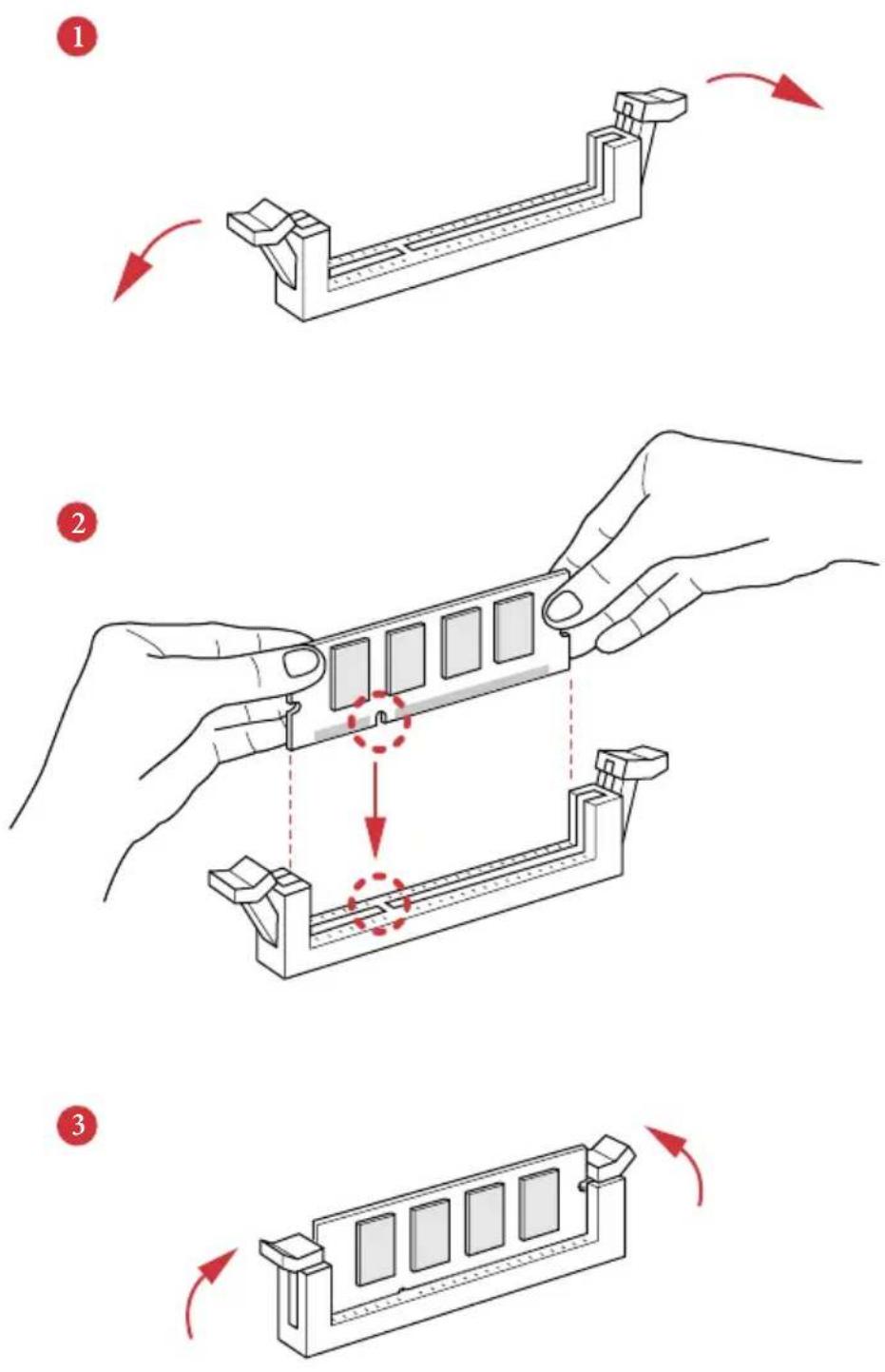
3.1.9 Installing Memory Modules (SO-DIMM)
This motherboard provides two 204-pin DDR3 (Double Data Rate 3) SO-DIMM slots.

It is not allowed to install a DDR or DDR2 memory module into a DDR3 slot; otherwise, this motherboard and SO-DIMM may be damaged.

The DIMM only fits in one correct orientation. It will cause permanent damage to the motherboard and the DIMM if you force the DIMM into the slot at incorrect orientation.
3.2 Replacing System Components
3.2.1 Replacing the Riser Card
- Replace the riser card.
text_image
Technical diagram of a device rear panel with labeled components and red arrows indicating parts 1 and 2.1 Align the riser card keys correctly with the expansion slot on the system board and insert it into place.
2 Fasten the two screws securing the riser card retention bracket.
3.2.2 Installing the Graphics Card
The M8 chassis supports both single-slot graphics card and dual-slot graphics card.

Before graphics card installation, please lift the VGA card holder and make sure the riser card is installed properly.
- Open the latch of the VGA card holder and remove the screws that secures the slot cover.
- Remove the slot cover(s) on the VGA card holder.
- Place your graphics card to the VGA card holder and secure it using screw(s).
- Close the latch to make sure the graphics card is securely seated.
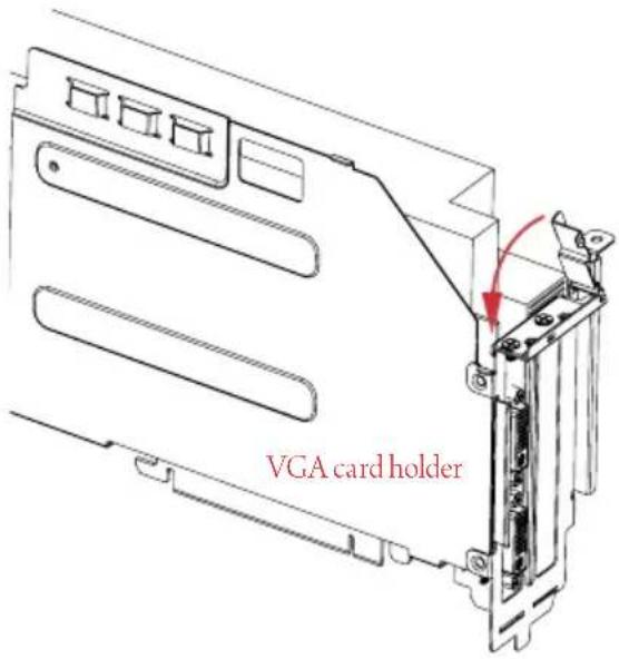
text_image
VGA card holderStandard-height card Over-height card
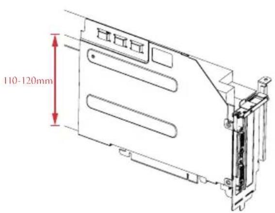
text_image
110-120mm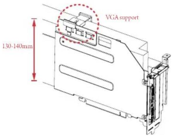
text_image
VGA support 130-140mm*If the graphics card you are using is over-height, use the VGA support to secure the card.
- Engage the VGA card holder with the two vertical sliding tracks while sliding it back to the chassis.
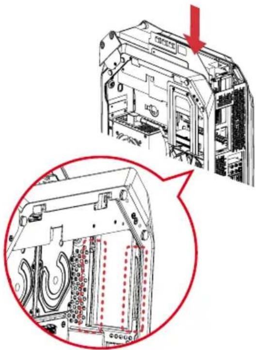
natural_image
Technical diagram of a computer tower with internal components and a magnified view showing internal structure (no text or symbols)- Make sure the VGA card holder is secured by the tongue plate and the graphics card is seated correctly.
natural_image
Technical line drawing of a mechanical assembly with internal components and a magnified inset showing a close-up detail (no text or symbols)- Secure the VGA card holder with the chassis using the two screws previously removed.
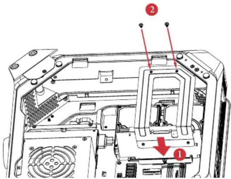
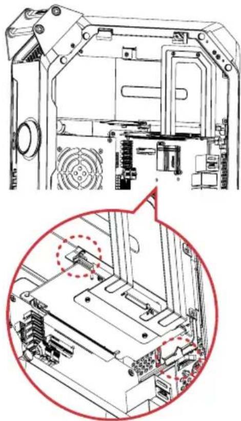
3.2.3 Replacing the Top Cover
- Place the system in an upright position.
- Make sure to release the left side panel.
- Connect the 4-pin top fan connector.

natural_image
Technical diagram of a mechanical assembly with highlighted internal components (no text or symbols)- Replace the top cover.

text_image
Technical diagram of a device interior with labeled components and directional arrows indicating flow or movement.1 Replace the top cover onto the chassis.
2 Slide the top cover toward the rear of the system until it clicks into place.
- Insert the mounting bracket into the mounting holes.

natural_image
Technical line drawing of a computer tower with visible internal components and a red arrow indicating direction (no text or symbols)- Secure it to the case with the three screws previously removed.
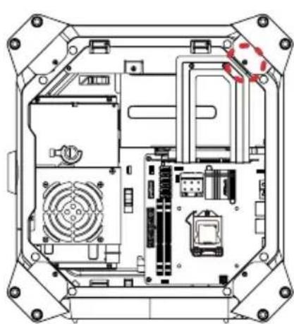
natural_image
Technical line drawing of an internal electronic device casing with visible circuitry and components (no text or symbols)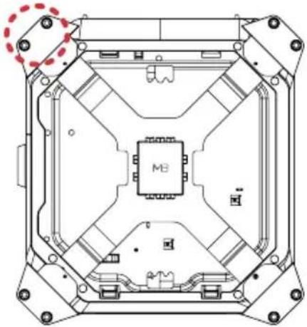
natural_image
Technical line drawing of an electronic component with internal circuitry and mounting holes (no text or symbols)3.2.1 Replacing the Side Panels
- Place the system in an upright position.
- Replace the side panels.
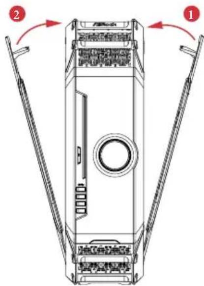
text_image
Technical diagram of a device casing with labeled components and directional arrows indicating assembly or movement.1 Snap the right side panel into place.
2 Snap the left side panel into place.
- Lock the system keylock on the top cover.

natural_image
Technical line drawing of a mechanical component with a red arrow indicating rotation (no text or symbols)Chapter 4 Motherboard
4.1 Motherboard Layout
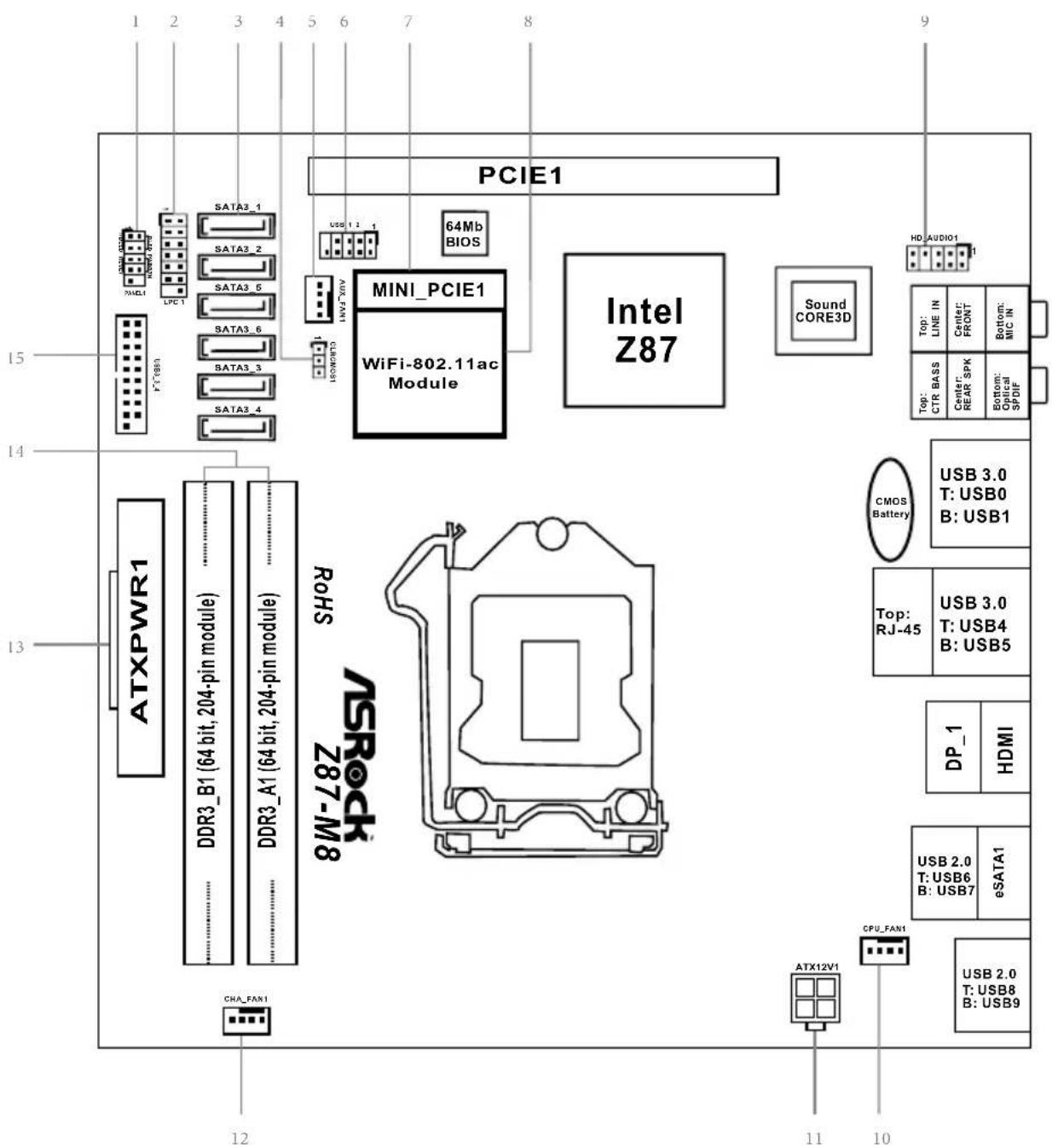
text_image
ATXPWR1 DDR3_B1 (64 bit, 204-pin module) DDR3_A1 (64 bit, 204-pin module) ATXPWR1 DDR3_B1 (64 bit, 204-pin module) DDR3_A1 (64 bit, 204-pin module) ATXPWR1 DDR3_B1 (64 bit, 204-pin module) DDR3_A1 (64 bit, 204-pin module) ATXPWR1 DDR3_B1 (64 bit, 204-pin module) DDR3_A1(64 bit, 204-pin module) ATXPWR1 DDR3_B1 (64 bit, 204-pin module) DDR3_A1(64 bit, 204-pin module) ATXPWR1 DDR3_B1 (64 bit, 204-pin module) DDR3_A1(64 bit, 204-pin module) ATXPWR1 DDR3_B1 (64 bit, Z87-M8) DDR3_A1(64 bit, Z87-M8) ATXPWR1 DDR3_B1 (64 bit, Z87-M8) DDR3_A1(64 bit, Z87-M8) ATXPWR1 DDR3_B1 (64 bit, Z87-M8) DDR3_A1(64 bit, Z87-M8) ATXPWR1 DDR3_B1 (64 bit, Z87-M8) DDR3_A1(64 bit Z87-M8) ATXPWR1 DDR3_B1 (64 bit, Z87-M8) DDR3_A1(64 bit Z87-M8) ATXPWR1 DDR3_B1 (64 bit, Z87-M8) DDR3_A1(64 bit Z87-M8) ATXPWR1 DDR3_B1 (64 bit, Z87-M8) DDR3_A1(54 bit Z87-M8) ATXPWR1 DDR3_B1 (64 bit, Z87-M8) DDR3_A1(54 bit Z87-M8) ATXPWR1 DDR3_B1 (64 bit, Z87-M8) DDR3_A1(54 bit Z87-M8) ATXPWR1 DDR3_B1 (64 bit, Z87-M8) DDR3_AI(54 bit Z87-M8) DDR3_B1 (64 bit, Z87-M8) DDR3_AI(54 bit Z87-M8) ATXPWR1 DDR3_B1 (64 bit, Z87-M8) DDR3_AI(54 bit Z87-M8) ATXPWR1 DDR3_B1 (64 bit, Z87-M8) DDR3_AI(54 bit Z87-M8) ATXPWR1 DDR3_B1 (64 bit, Z87-M8) DDR3_AI(54 bit Z87-M8) ATXPW CPU_FAN CPU_FAN USB_2.0 T:USB_2.0 B:USB_2.0 eSATA1 USB_2.0 T:USB_2.0 B:USB_2.0 CPU_FAN CPU_FAN USB_2.0 T:USB_2.0 B:USB_2.0 DP_1 HDMI Top: RJ-45 USB_3.0 T:USB_3.0 B:USB_3.0 USB_3.0 T:USB_3.0 B:USB_3.0 CMOS Battery Top: CTR BASS Top: LINE IN Center: REAR SPK Center: FRONT Bottom: Optical SPDF Bottom: MIC IN HD:AUDIO 9No. Description
1 System Panel Header (PANEL1)
2 LPC Debug Header (LPC1)
3 SATA3 Connectors
(SATA3_1, SATA3_2, SATA3_3, SATA3_4, SATA3_5, SATA3_6)
4 Clear CMOS Jumper (CLRCMOS1)
5 Auxiliary Fan Connector (AUX_FAN1)
6 USB 2.0 Header (USB_1_2)
7 mini-PCI Express Slot (MINI_PCIe1)
8 WiFi-802.11ac Module
9 Front Panel Audio Header (HD_AUDIO1)
10 CPU Fan Connector (CPU_FAN1)
11 ATX 12V Power Connector (ATX12V1)
12 Chassis Fan Connector (CHA_FAN1)
13 ATX Power Connector (ATXPWR1)
14 2 x 204-pin DDR3 SO-DIMM Slots (DDR3_A1, DDR3_B1)
15 USB 3.0 Header (USB3_3_4)
4.2 Jumpers Setup
The illustration shows how jumpers are setup. When the jumper cap is placed on the pins, the jumper is "Short". If no jumper cap is placed on the pins, the jumper is "Open". The illustration shows a 3-pin jumper whose pin1 and pin2 are "Short" when a jumper cap is placed on these 2 pins.
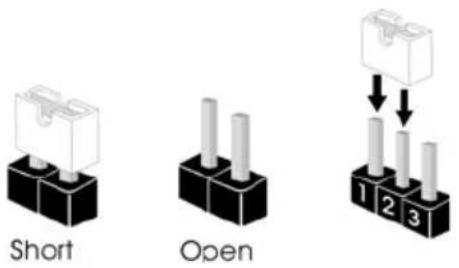
text_image
Short OpenClear CMOS Jumper (CLRCMOS1)
(see p.41, No. 31)

Default
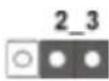
Clear CMOS
CLRCMOS1 allows you to clear the data in CMOS. To clear and reset the system parameters to default setup, please turn off the computer and unplug the power cord from the power supply. After waiting for 15 seconds, use a jumper cap to short pin2 and pin3 on CLRCMOS1 for 5 seconds. However, please do not clear the CMOS right after you update the BIOS. If you need to clear the CMOS when you just finish updating the BIOS, you must boot up the system first, and then shut it down before you do the clear-CMOS action. Please be noted that the password, date, time, and user default profile will be cleared only if the CMOS battery is removed.

The Clear CMOS Button has the same function as the Clear CMOS jumper.
4.3 Onboard Headers and Connectors

Onboard headers and connectors are NOT jumpers. Do NOT place jumper caps over these headers and connectors. Placing jumper caps over the headers and connectors will cause permanent damage to the motherboard.
System Panel Header (9-pin PANEL1)
(see p.41, No. 1)
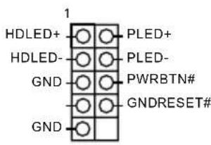
text_image
1 HDLED+ HDLED- GND GND PLED+ PLED- PWRBTN# GNDRESET#Connect the power switch, reset switch and system status indicator on the chassis to this header according to the pin assignments below. Note the positive and negative pins before connecting the cables.

PWRBTN (Power Switch):
Connect to the power switch on the chassis front panel. You may configure the way to turn off your system using the power switch.
RESET (Reset Switch):
Connect to the reset switch on the chassis front panel. Press the reset switch to restart the computer if the computer freezes and fails to perform a normal restart.
PLED (System Power LED):
Connect to the power status indicator on the chassis front panel. The LED is on when the system is operating. The LED keeps blinking when the system is in S1/S3 sleep state. The LED is off when the system is in S4 sleep state or powered off (S5).
HDLED (Hard Drive Activity LED):
Connect to the hard drive activity LED on the chassis front panel. The LED is on when the hard drive is reading or writing data.
The front panel design may differ by chassis. A front panel module mainly consists of power switch, reset switch, power LED, hard drive activity LED, speaker and etc. When connecting your chassis front panel module to this header, make sure the wire assignments and the pin assignments are matched correctly.
Serial ATA3 Connectors
(SATA3_1)
(SATA3_2)
(SATA3_5)
(SATA3_6)
(SATA3_3)
(SATA3_4)
(see p.41, No. 3)
SATA3 1

SATA3 2

SATA3 5

SATA3 6

SATA3 3

SATA3 4

These six SATA3
connectors support SATA data cables for internal storage devices with up to 6.0 Gb/s data transfer rate. SATA3_4 connector is shared with the eSATA port.
USB 2.0 Headers
(9-pin USB_1_2)
(see p.41, No. 6)
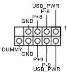
text_image
USB_PWR P-8 GND P+8 1 DUMMY GND P+9 P-9 USB_PWRBesides two USB 2.0 ports on the I/O panel, there are two headers on this motherboard. Each USB 2.0 header can support two ports.
USB 3.0 Headers
(19-pin USB3_3_4)
(see p.41, No. 15)
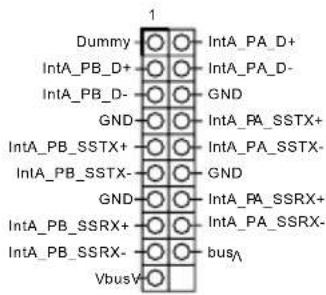
text_image
Dummy IntA_PB_D+ IntA_PB_D- GND IntA_PB_SSTX+ IntA_PB_SSTX- GND IntA_PB_SSRX+ IntA_PB_SSRX- VbusV INTA_PA_D+ INTA_PA_D- GND INTA_PA_SSTX+ INTA_PA_SSTX- GND INTA_PA_SSRX+ INTA_PA_SSRX- busABesides four USB 3.0 ports on the I/O panel, there are one header on this motherboard. Each USB 3.0 header can support two ports.
Front Panel Audio Header
(9-pin HD_AUDIO1)
(see p.41, No. 9)
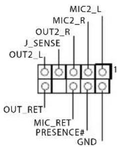
text_image
MIC2_L MIC2_R OUT2_R J_SENSE OUT2_L 1 OUT_RET MIC_RET PRESENCE# GNDThis header is for connecting audio devices to the front audio panel.

- High Definition Audio supports Jack Sensing, but the panel wire on the chassis must support HDA to function correctly. Please follow the instructions in our manual and chassis manual to install your system.
- If you use an AC'97 audio panel, please install it to the front panel audio header by the steps below:
A. Connect Mic_IN (MIC) to MIC2_L.
B. Connect Audio_R (RIN) to OUT2_R and Audio_L (LIN) to OUT2_L.
C. Connect Ground (GND) to Ground (GND).
D. MIC_RET and OUT_RET are for the HD audio panel only. You don't need to connect them for the AC'97 audio panel.
E. To activate the front mic, go to the "FrontMic" Tab in the Realtek Control panel and adjust "Recording Volume".
Chassis and Auxiliary
Fan Connectors
(4-pin CHA_FAN1)
(see p.41, No. 12)
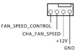
text_image
FAN_SPEED_CONTROL CHA_FAN_SPEED +12V GNDPlease connect fan cables to the fan connectors and match the black wire to the ground pin.
(4-pin AUX_FAN1)
(see p.41, No. 12)

CPU Fan Connectors
(4-pin CPU_FAN1)
(see p.41, No. 10)

text_image
4 3 2 1 GND +12V CPU_FAN_SPEED FAN_SPEED_CONTROLThis motherboard provides a 4-Pin CPU fan
(Quiet Fan) connector.
If you plan to connect a
3-Pin CPU fan, please connect it to Pin 1-3.
ATX Power Connector
(24-pin ATXPWR1)
(see p.41, No. 5)
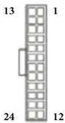
This motherboard provides a 24-pin ATX power connector. To use a 20-pin ATX power supply, please plug it along Pin 1 and Pin 13.
ATX 12V Power
Connector
(4-pin ATX12V1)
(see p.41, No. 13)
This motherboard
provides a 4-pin ATX 12V power connector. To use a 8-pin ATX power supply, please plug in 4 of the 8 pins (Pin 1 to Pin 4).
LPC Debug Header
(13-pin LPC1)
(see p.41, No. 2)

PINSignal Name PINSignal Name
| 14 +3V 13 No pin | ||
| 12 +3V 11 +3V | ||
| 10 GND 9 GND | ||
| 8 LAD3 7 LAD2 | ||
| 6 LAD1 5 LAD0 | ||
| 4 LFRAME# 3 RESET# | ||
| 2 GND 1 CLK |
Chapter 5 Software and Utilities Operation
5.1 Installing Drivers
The Support CD that comes with the M8 contains necessary drivers and useful utilities that enhance the M8's features.
Running The Support CD
To begin using the support CD, insert the CD into your CD-ROM drive. The CD automatically displays the Main Menu if “AUTORUN” is enabled in your computer. If the Main Menu does not appear automatically, locate and double click on the file “ASRSETUP.EXE” in the Support CD to display the menu.
Drivers Menu
The drivers compatible to your system will be auto-detected and listed on the support CD driver page. Please click Install All or follow the order from top to bottom to install those required drivers. Therefore, the drivers you install can work properly.
Utilities Menu
The Utilities Menu shows the application software that the motherboard supports. Click on a specific item then follow the installation wizard to install it.

To improve Windows 7 compatibility, please download and install the following hot fix provided by Microsoft.
"KB2720599": http://support.microsoft.com/kb/2720599/en-us
5.2 A-Tuning
A-Tuning is ASRock's multi purpose software suite with a new interface, more new features and improved utilities, including XFast RAM, Dehumidifier, Good Night LED, FAN-Tastic Tuning, OC Tweaker and a whole lot more.
5.2.1 Installing A-Tuning
When you install the all-in-one driver to your system from ASRock's support CD, A-Tuning will be auto-installed as well. After the installation, you will find the icon "A-Tuning" on your desktop. Double-click the "A-Tuning" icon, A-Tuning main menu will pop up.
5.2.2 Using A-Tuning
There are five sections in A-Tuning main menu: Operation Mode, Tools, OC Tweaker, System Info and Tech Service.
Operation Mode
Choose an operation mode for your computer.

text_image
ASRock A-Tuning Operation Mode Timing OC Transition System Tools User Updates Tools & Inversions Start up Operation Mode Performance Mode Standard Mode Power Saving Description Change an operation mode for your computerTools
Various tools and utilities.

text_image
ASRock A-Tuning Tools Acceleration Sheet Active Sheet Active Part Book LifeStyle SPE My-Table Tuning Demutrition City Puzzle LSE Key CC Only Desorption Variant tools and utilitiesXFast RAM
Boost the system's performance and extend the HDD's or SDD's lifespan! Create a hidden partition, then assign which files should be stored in the RAM drive.
XFast LAN
Boost the speed of your internet connection! Select a specific mode for making the designated program's priority highest.
Fast Boot
Fast Boot minimizes your computer's boot time. Please note that Ultra Fast mode is only supported by Windows 8 and the VBIOS must support UEFI GOP if you are using an external graphics card.
OMG
Schedule the starting and ending hours of internet access granted to other users. Place X marks on the time table to disable the internet.
FAN-Tastic Tuning
Configure up to five different fan speeds using the graph. The fans will automatically shift to the next speed level when the assigned temperature is met.
Dehumidifier
Prevent motherboard damages due to dampness. Enable this function and configure the period of time until the computer powers on, and the duration of the dehumidifying process.
Key Master
Enhance your mouse and keyboard with customizable macros, sniper modes, scroll speed, key repeat rates and repeat delay.
USB Key
Plug in the USB Key and let your computer log in to windows automatically!
OC DNA
In OC DNA, you can save your OC settings as a profile and share with your friends. Your friends then can load the OC profile to their own system to get the same OC settings.
OC Tweaker
Configurations for overclocking the system.

text_image
ASRock A-Tuning Open adjust Mode Down OC Tweaker Open adjust Mode Up to Open Power Increase Settings OC Tweaker Cock AC (AC) of Frequency 100.92 MHz CP (CP) Rate x390 SP (SP) Rate x390 ST (ST) Rate 1256 MHz Voltage OP (OP) Load Voltage (Off) 40 V OP (OP) Score Load Voltage Rate Adaptive Mode Over DC Rate Power Adaptive Voltage 4000 Auto apply when program team Description Configurations for user tracking the systemSystem Info
View information about the system.

text_image
ASRock A-Tuning System Info System Information CLOCK CPU Frequency 2840 GB MHz C7 Frequency 800 PCC Frequency 100.00 MHz CPU Rate ×9 CPU Cache Rate ×6 EPS & TEMPERATURE CPU Temperature 4132.183P ±40Hz PSB Temperature 290/0.4V CPU Part 1 Speed 0 RPM Drums Part 1 Speed 2254 RPM VOLTAGE CPU Input Time 1.770 s +1.0V V 12.264 s CPU Cache Vcc Offset +0.306 s CPU Atering to output Offset +0 s Volume Vcc +2.3V Vcc +1.0V Vcc +5.6V Vcc +1.0V Vcc +5.6V Vcc +5.6V Vcc +5.6V Vcc +5.6V Vcc +5.6V Vcc +5.6V Vcc +5.6V Vcc +5.6V Vcc +5.6V Vcc +5.6V Vcc +5.6V Vcc +5.6V Vcc +5.6V VccLive Update
Check for newer versions of BIOS, A-Tuning or drivers.

text_image
ASRock A-Tuning Live Update Live Update Custom Version Latest Version Sensed: 4756 Description Check the name version of BIOS or drives.Tech Service
Contact Tech Service.
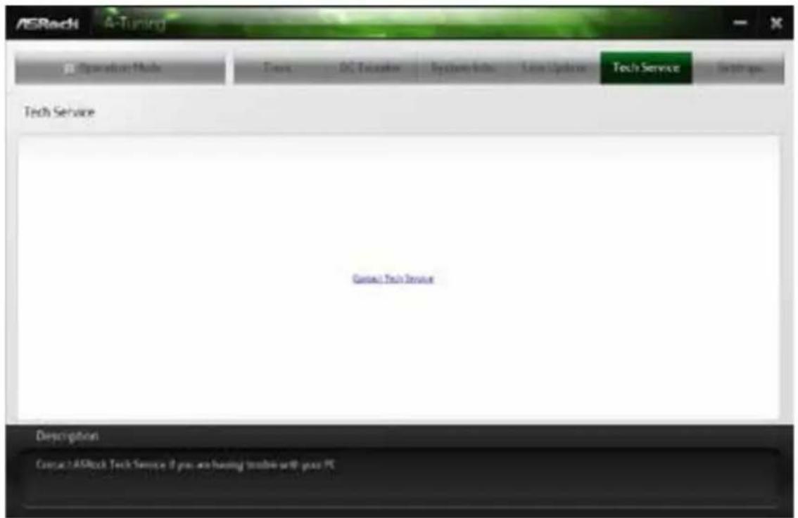
text_image
ASRock A-Tuning Operation Tools Fax: DC Tolerance System Tools New Update Tech Service In 100 pm Tech Service Contact Tech Service Description Contact ASRock Tech Service 2 pro are having tools with pass PCSettings
Configure ASRock A-Tuning.

text_image
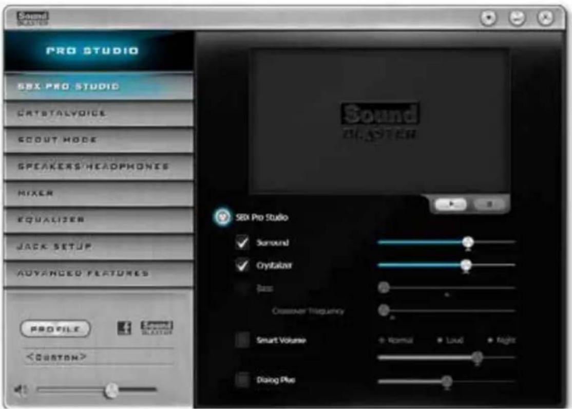
ASRock A-Tuning E:\Connection Mode Cana OS Transitions System Tools User Analytes Fraci Software Settings Setting Ameris et Medusa Sansai Version: 20.27.1 Description Configure ASRock & Scaling5.3 SBX Pro Studio
This section explains how to configure the Creative Sound Core3D using SBX Pro Studio.
text_image
Sound STOCK PRO STUDIO SIX PRO STUDIO CRYSTALVOICE SCOUT MODE SPEAKERS/HEADPHONES MIXER EQUALIZER JACK SETUP ADVANCED FEATURES PROFILEClick the power button on the left to activate or deactivate.
Surround
Control the level of audio immersion in music, movies and games.
Crystalizer
Enhance music and movies to make them sound livelier.
Bass
Control the desired level of bass.
Crossover Frequency
Redirect all frequencies below this value to the optimal speaker for better bass response.
Smart Volume
Adjust the loudness of your audio playback automatically to minimize sudden volume changes.
Dialog Plus
Enhance the voices in movies for clearer dialog.
CRYSTALVOICE

text_image
PRO STUDIO SEX PRO STUDIO CRYSTALYDICE SCOUT MODE SPEAKERS/HEADPHONES MIXER EQUALIZER JACK SETUP ADVANCED FEATURES PROFILESelect a recording device
Mic Volume
Control the level of mic volume.
Mic Boost
Control the level of mic boost.
CrystalVoice
Click the power button on the left to activate or deactivate.
FX
Morph your voice into different characters and accents.
Smart Volume
Be heard clearly without having to shout or whisper.
Noise Reduction
Eliminate unwanted background noise in your conversation.
Acoustic Echo Cancellation
Eliminate echoes that interfere with your conversation.
SCOUT MODE

text_image
PRO STUDIO SEX PRO STUDIO CRYSTALVOICE SCOUT MODE SPEAKERS/HEADPHONES HIXER EQUALIZER JACK SETUP ADVANCED FEATURES PROFILEScout Mode
Enable or disable scout mode. This proprietary technology allows you to hear your enemies from further away, giving you a distinct tactical advantage in combat.
Hot Key Configuration
Configure hot keys to enable or disable scout mode.
SPEAKERS/HEADPHONES
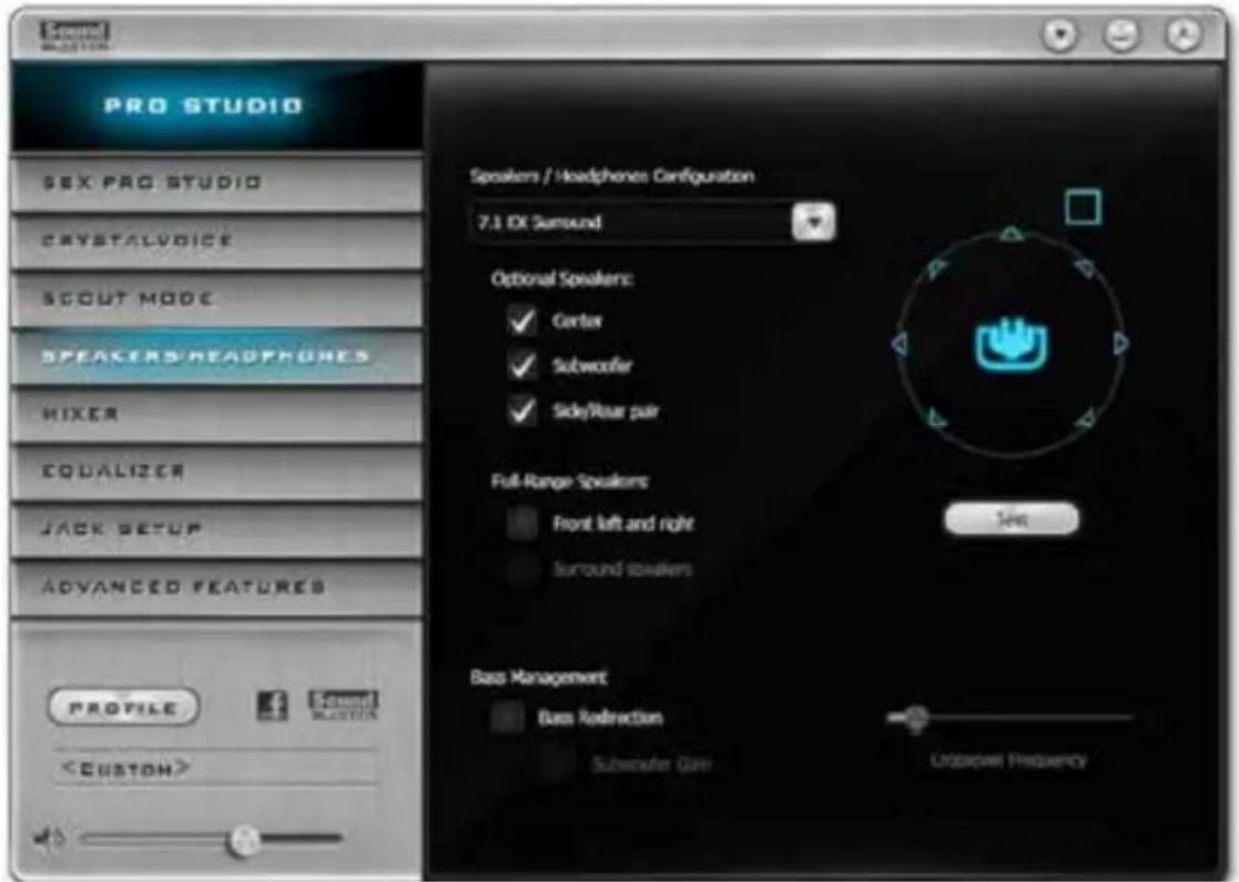
text_image
PRO STUDIO SEX PRO STUDIO CRYSTALVOICE SCOUT MODE SPEAKERS HEADPHONES HIXER EQUALIZER JACK SETUP ADVANCED FEATURES PROFILESpeakers / Headphones Configuration
Select the device connected.

If there are both speakers and front headphones connected, please select the device you desire to use as audio output.
Optional Speakers
Center
Enable or disable center speaker.
Subwoofer
Enable or disable subwoofer.
Rear pair
Enable or disable rear pair speakers.
Full-Range Speakers:
Select full-range speakers.
Bass Management
Bass Redirection
Enable or disable bass redirection.
Subwoofer Gain
Enable or disable subwoofer gain.
Crossover Frequency
Redirect all frequencies below this value to the optimal speaker for better bass response.
MIXER
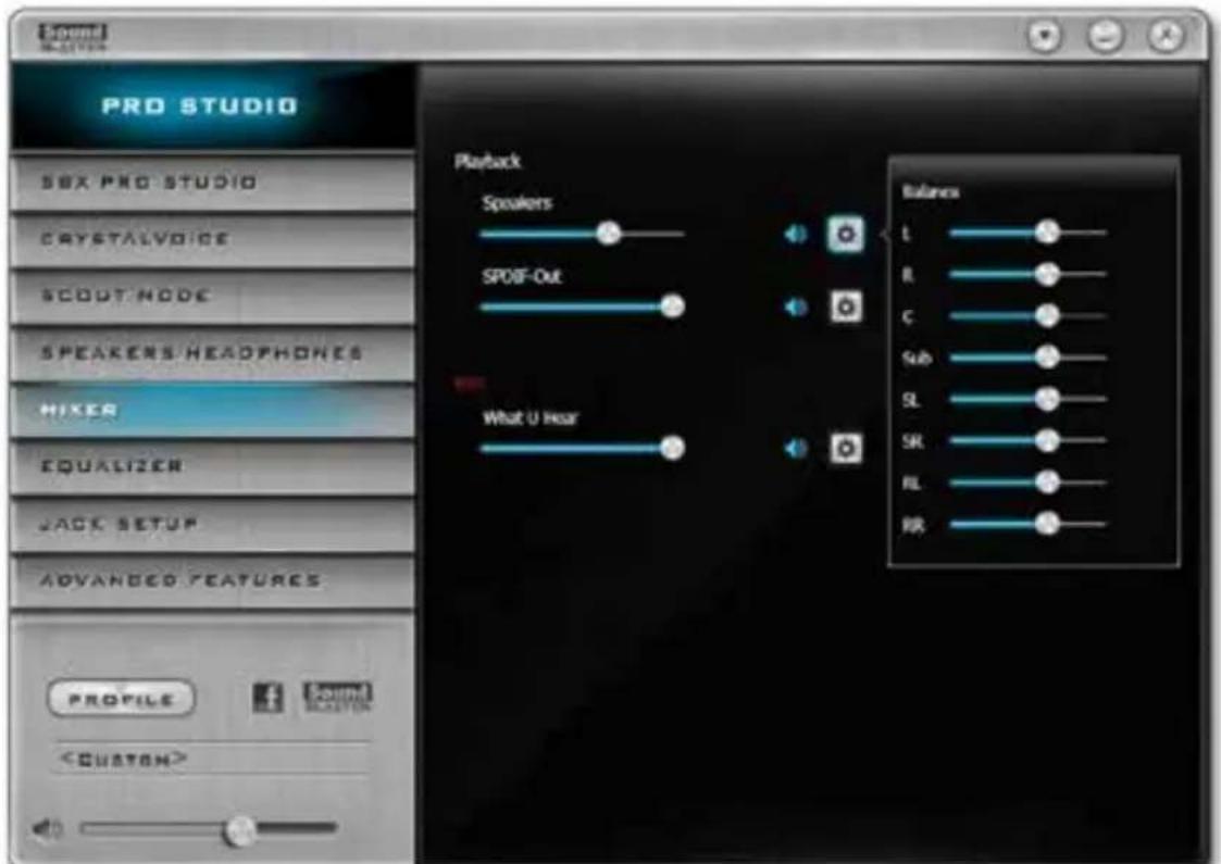
text_image
Pro Studio SBX PRO STUDIO CRYSTALVOICE SCOUT NODE SPEAKERS HEADPHONES MIXER EQUALIZER JACK SETUP ADVANCED FEATURES PROFILEPlayback
Speakers
Control the level of speakers playback.
SPDIF-Out
Control the level of SPDIF-Out playback.
Balance
Control the level of various speaker's balance.
REC
What U Hear
Control the level of playback redirect.
EQUALIZER

text_image
PRO STUDIO SEX PRO STUDIO CRYSTALVOICE SCOUT MODE SPEAKERS HEADPHONES MIXER EQUALIZEN JACK SETUP ADVANCED FEATURES PROFILEEQ
Choose from Flat, Acoustic, Classical, Country, Dance, Jazz, New Age, Pop, Rock and Vocal.
JACK SETUP
Device Connected:
Select the device connected.
Show Jack Setup dialog when an audio jack is inserted
Enable or disable Jack Setup dialog.
ADVANCED FEATURES
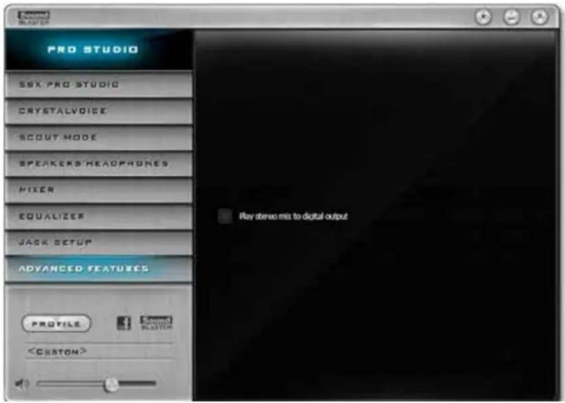
text_image
PRO STUDIO SSK PRO STUDIO CRYSTALVOICE SCOUT MODE SPEAKERS HEADPHONES MIXER EQUALIZER JACK SETUP ADVANCED FEATURES ProfilePlay stereo mix to digital output
Enable or disable play stereo mix to digital output.
PROFILE
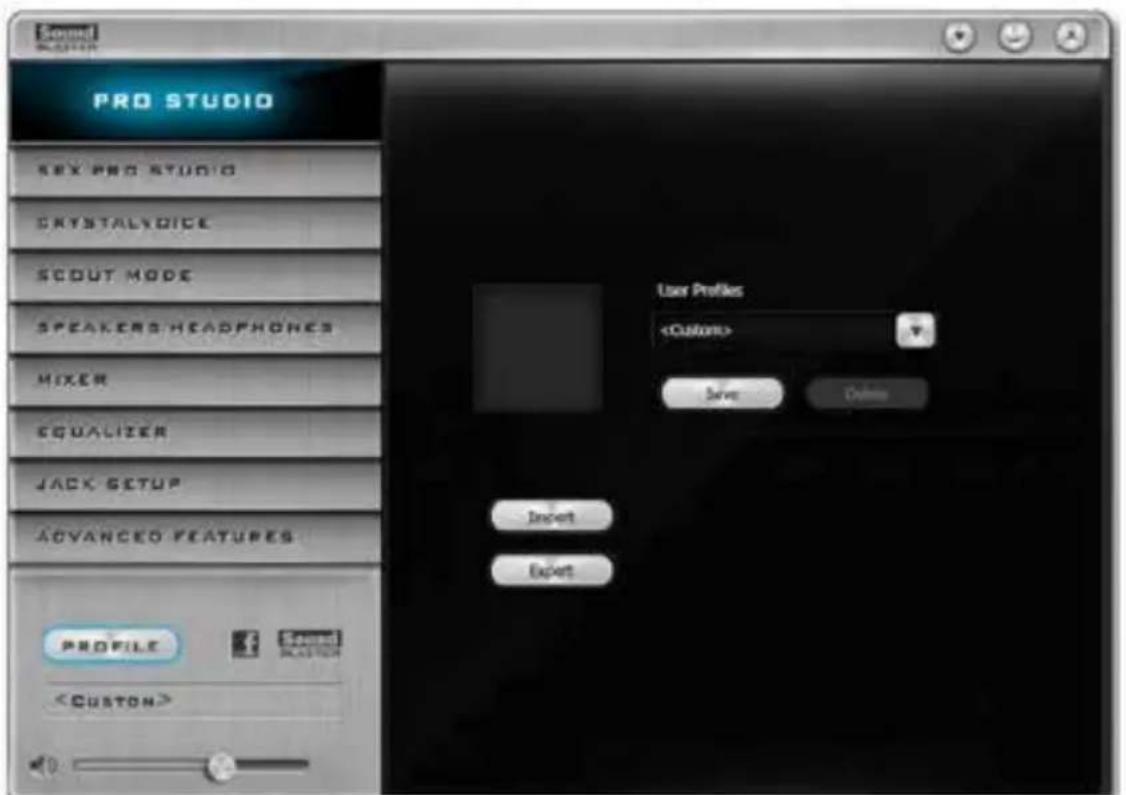
text_image
Sound PRO STUDIO SEX PRO STUDIO CRYSTALVOICE SCOUT MODE SPEAKERS HEADPHONES MIXER EQUALIZER JACK SETUP ADVANCED FEATURES ProfileUser Profiles
You can save, load or delete your user profiles. The default is
Note
- If you want to hear your own voice through the microphone (Playback mode). You can change your settings to " playback mode" by checking the "Listen to this device" box in Control panel > Sound > Recording > Microphone > Properties > Listen.

text_image
Microphone Properties General Listen Levels Advanced You can listen to a portable music player or other device through this microphone jack. If you correct a microphone, you may hear feedback. Listen to this device Playback through this device: Default Playback Device- If you want to change your playback device to a SPDIF-Out device, go into Control panel > Sound > Playback, then right click on SPDIF-Out and check the "Set as Default Device" option.

text_image
Select a sound device below to modify its settings Sounders ST Server/STS Default Device SPSP Cloud 50 (Standard) Project Test Disable Set as Default Device Set as Default Communication Device Show Disabled Devices Show Disconnected Devices Properties Cancel Set Default Proportion: OK Cancel Help5.4 Intel® Rapid Start Technology
Intel® Rapid Start Technology enables your system to wake up faster from deep sleep, saving time and power consumption. Feel secure to know that your system will resume to working condition even if an unexpected power loss happens while the PC is in sleep mode.
5.4.1 System Requirements
- Confirm whether your motherboard supports this feature.
• Operating system: Microsoft Windows 8/7 (32- or 64-bit edition) - Set the SATA mode to AHCI. If Windows 8/7 is already installed under IDE mode, directly changing the SATA mode to AHCI may cause Windows 8/7 to crash while booting. If your system is not in AHCI mode, please follow the instructions below.

There are certain risks. Please backup any important data before operating to avoid loss.
- Press Win + R simultaneously in Windows 8/7, type "Regedit" into the word box then click OK.

text_image
Run Type the name of a program, folder, document, or Internet resource, and Windows will open it for you. Open: regedit OK Cancel Browse...- Enter into HKEY_LOCAL_MACHINE\SYSTEM\CurrentControlSet\services\msahci in Windows Registry Editor. Double click on the value Start and change the value from 3 into 0. Click on OK.
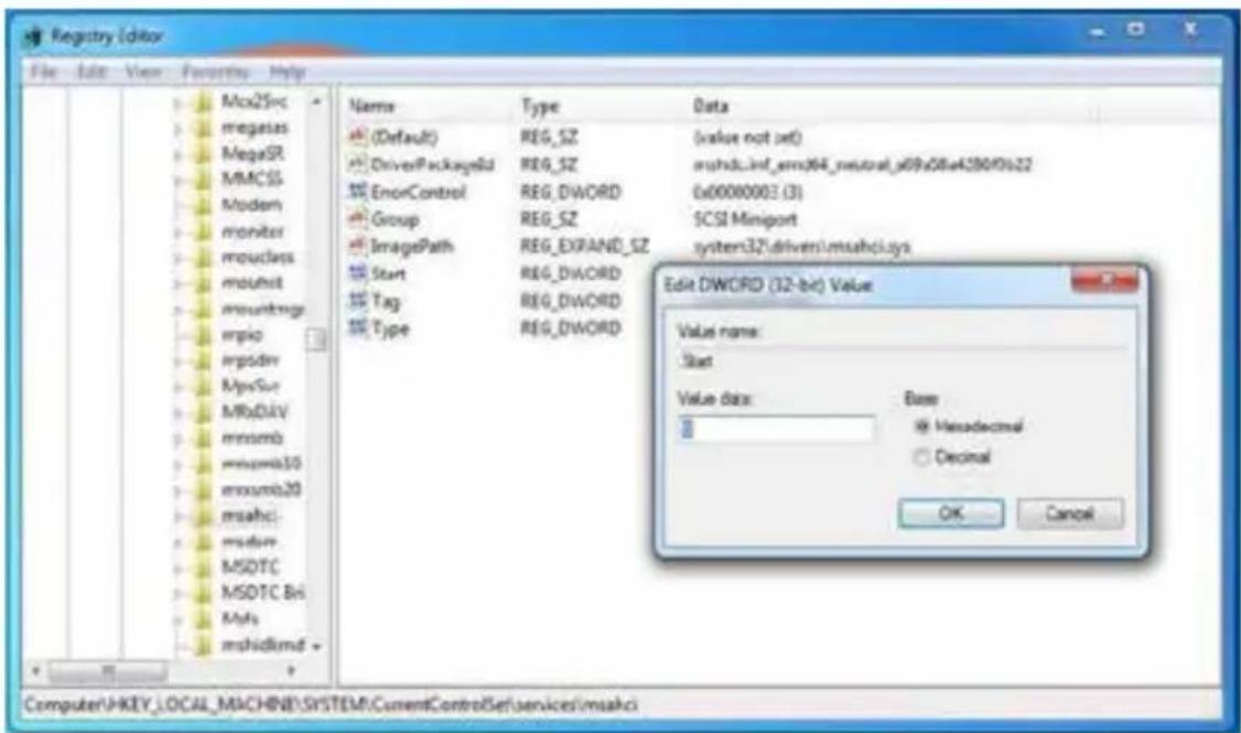
text_image
Registry Editor File Edit View Favorites Help Mcx25rc megasys MegaSR MMCSS Modern monitor mouclass msuhit mountrags mpio mpdiv MysSur MRbDiv mmsmb mmsmb30 mmsmb20 msahci msdav MSDTC MSDTC Bti Msfs mshidlmd + Name Type Data (Default) REG_SZ (value not set) DriverPackageID REG_SZ mshdb_inf_em364_neutral_s09a08e4280f0s22 ErrorControl REG_DWORD 0x00000003 (3) Group REG_SZ SCSI Miniport ImagePath REG_EXPAND_SZ system32\driver\msahci.sys Start REG_DWORD Tag REG_DWORD Type REG_DWORD Edit DWORD (32-bit) Value Value name: Start Value data: Base Hexadecimal Decimal OK Cancel Computer:\AKEY_LOCAL_MACHINE\SYSTEM\CurrentControlSet\Services\msahci- Exit the Registry Editor window and restart the computer.
- Press F2 to enter BIOS, then go to Advanced -> Storage Configuration and change SATA Mode to AHCI. Press F10 to save changes and exit.
- Enter Windows 8/7. Windows will discover the new device and install AHCI drivers automatically.
5.4.2 Setup Guide
Configuring Rapid Start
Step 1
Run ASRock Rapid Start utility from Start -> All Programs -> ASRock Utility.
Step 2
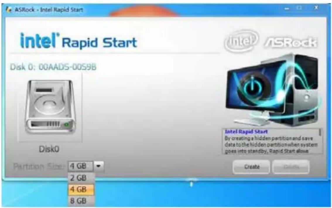
If you have more than one hard drives in your system, you must select one, then choose the Partition Size desired for your hidden partition and click on Create. The system will automatically create a hidden partition according to your settings. If there are SSD's installed into your system, it is recommended to create the partition on the SSD.
text_image
ASRock - Intel Rapid Start intel® Rapid Start Disk 0: 00AADS-00S9B Disk0 Partition Size: 4 GB 2 GB 4 GB 8 GB Intel® ASRock Intel Rapid Start By creating a hidden partition and save data to the hidden partition when system goes into standby, Rapid Start allows Create DeleteStep 3
When prompted to restart after the setup, click Yes to reboot.

text_image
ASRock - Intel Rapid Start intel® Rapid Start Disk 0: 00AAKX-221CA , Creating.....Done. Reboot You need to restart the system, Would you like to restart now? Yes No Partition Size: 4 GB DeleteStep 4
Double-click the Intel® Rapid Start Technology Manager icon in the Windows system tray.
Step 5
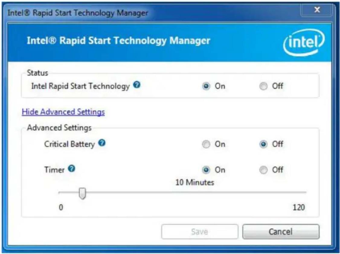
Make sure Rapid Start is on. Drag the slider to configure the time. For example, if the timer value is set to ten minutes, the system will enable Rapid Start mode after entering sleep state for ten minutes. If the timer is set to 0 minutes, Windows will immediately enable Rapid Start mode as it enters sleep state.
text_image
Intel® Rapid Start Technology Manager Intel® Rapid Start Technology Manager Status Intel Rapid Start Technology ? On Off Hide Advanced Settings Advanced Settings Critical Battery ? On Off Timer ? On Off 10 Minutes 0 120 Save CancelUsing Rapid Start
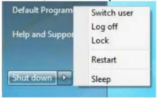
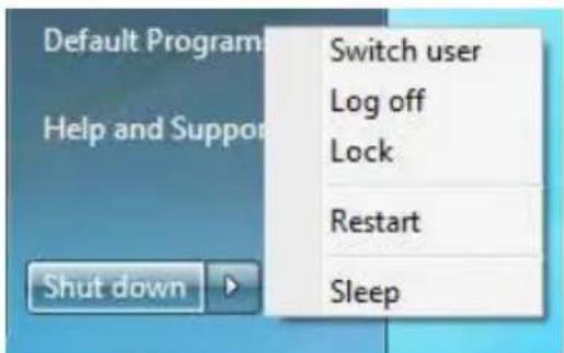
- You may shut down the computer without terminating the applications or files you are executing currently. Click on Windows Start -> the arrow next to Shut down, and click on Sleep.
text_image
Default Program Help and Support Shut down Switch user Log off Lock Restart Sleep- Windows system will enter sleep state.
- According to your settings in Rapid Start Technology Manager, the system
will automatically wake up and enable Rapid Start mode after entering sleep state for a period of time. The power of the computer in Rapid Start mode can be cut off, it will not cause data loss of the programs or files you were executing before entering sleep state.
- When you wish to continue to use the computer just hit the power button, the system will rapidly return to Windows, the programs and files which you were using before entering sleep state will be accessible immediately.
5.5 Intel® Smart Connect Technology
Intel® Smart Connect Technology is a feature that periodically wakes your computer from Windows® sleep state to refresh email or social networking applications. It saves your waiting time and keeps the content always up-to-date.
5.5.1 System Requirements
- Confirm whether your motherboard supports this feature.
• Operating system: Microsoft Windows 8/7 (32- or 64-bit edition) - Set the SATA mode to AHCI. If Windows 8/7 is already installed under IDE mode, directly changing the SATA mode to AHCI may cause Windows 8/7 to crash while booting. If your system is not in AHCI mode, please follow the instructions below.

There are certain risks. Please backup any important data before operating to avoid loss.
- Press Win + R simultaneously in Windows 8/7, type "Regedit" into the word box then click OK.
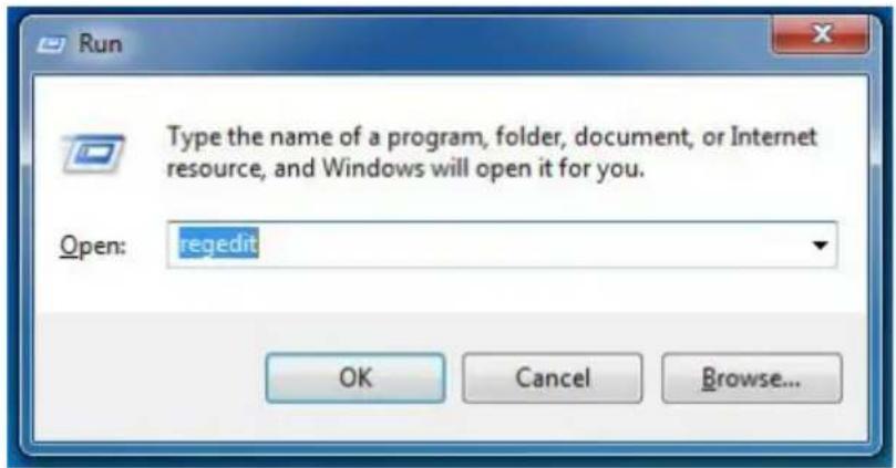
text_image
Run Type the name of a program, folder, document, or Internet resource, and Windows will open it for you. Open: regedit OK Cancel Browse...- Enter into HKEY_LOCAL_MACHINE\SYSTEM\CurrentControlSet\services\msahci in Windows Registry Editor. Double click on the value Start and change the value from 3 into 0. Click on OK.
5.5.2 Setup Guide
Installing ASRock Smart Connect Utility
Step 1
Install ASRock Smart Connect Utility, which is located in the folder at the following path of the Support CD: \ ASRock Utility > Smart Connect.
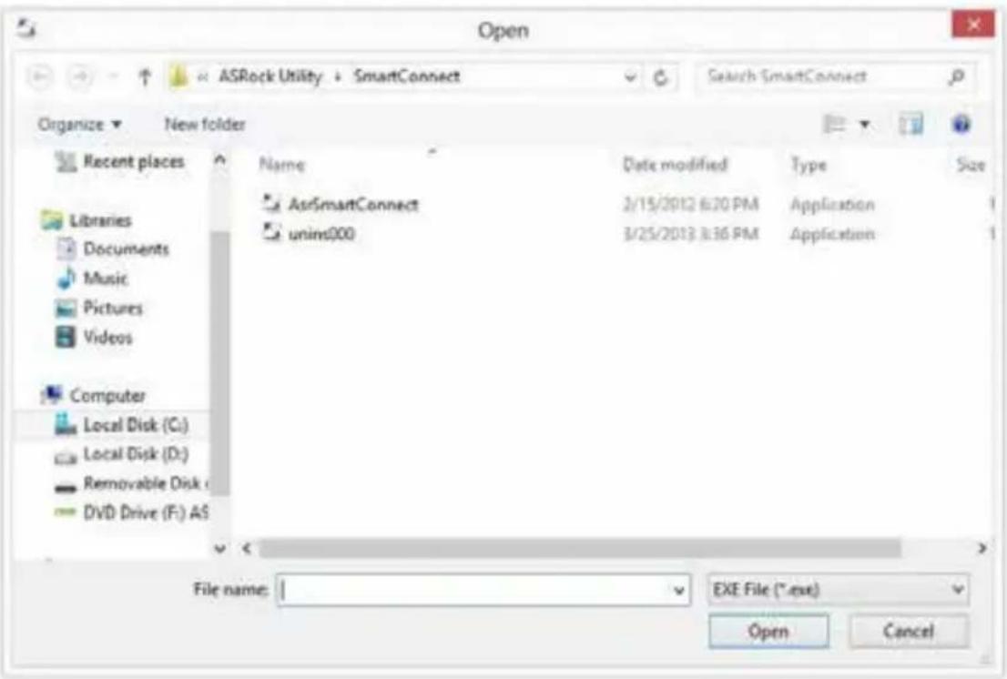
text_image
Open ASRock Utility + SmartConnect Search SmartConnect Organize ▼ New folder Recent places Name Date modified Type Size AsrSmartConnect 2/15/2012 6:30 PM Application unim000 3/25/2013 8:36 PM Application Computer Local Disk (C:) Local Disk (D:) Removable Disk ( DVD Drive (F:) AS File name: I EXE File (*.exe) Open CancelStep 2
Once installed, run ASRock Smart Connect from your desktop or go to Windows Start -> All Programs -> ASRock Utility.
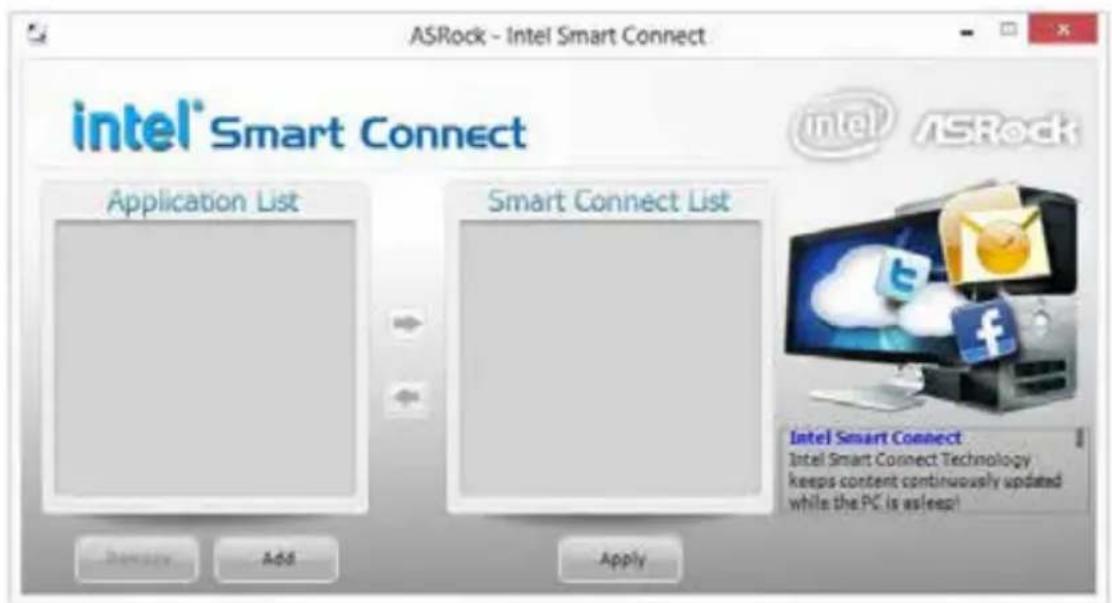
text_image
ASRock - Intel Smart Connect intel® Smart Connect Application List Smart Connect List Intel Smart Connect Intel Smart Connect Technology keeps content continuously updated while the PC is asleep!Step 3
Click the Add button. Take Foxmail as an example, add Foxmail to the Application list.
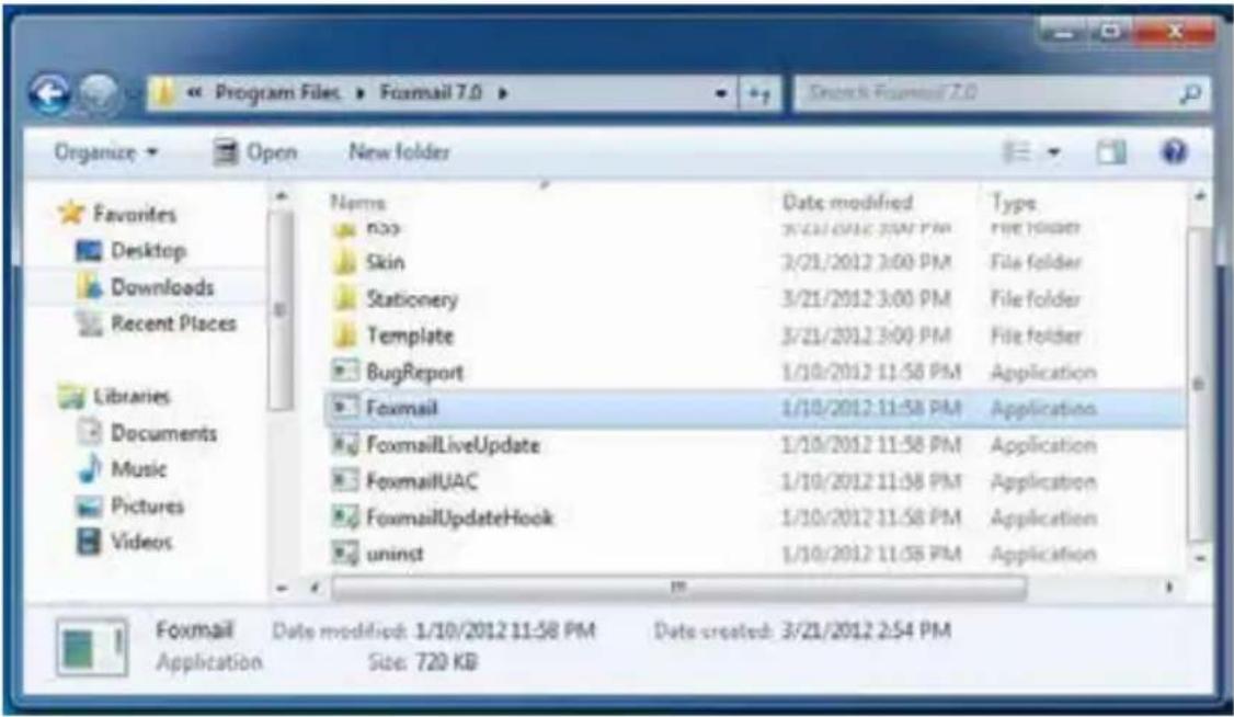
text_image
Program Files > Foxmail 7.0 Organize > Open New folder Favorites Desktop Downloads Recent Places Libraries Documents Music Pictures Videos Name Date modified Type Box 3/21/2012 3:00 PM free folder Skin 3/21/2012 3:00 PM File folder Stationery 3/21/2012 3:00 PM File folder Template 3/21/2012 3:00 PM File folder BugReport 1/10/2012 11:58 PM Application Foxmail 1/10/2012 11:58 PM Application FoxmailLiveUpdate 1/10/2012 11:58 PM Application FoxmailUAC 1/10/2012 11:58 PM Application FoxmailUpdateHook 1/10/2012 11:58 PM Application uninst 1/10/2012 11:58 PM Application Foxmail Date modified: 1/10/2012 11:58 PM Date created: 3/21/2012 2:54 PM Application Size: 720 KBStep 4
Select Foxmail from the Application List, then click the arrow pointing right to add this application to the Smart Connect List.

text_image
ASRock - Intel Smart Connect intel® Smart Connect Application List FormaLone Smart Connect List Remove Add Apply Intel® ASRock Intel Smart Connect Intel Smart Connect Technology keeps content continuously updated while the PC is asleep!Step 5
Click Apply to enable Smart Connect.
Step 6
Double-click the Intel® Smart Connect Technology Manager icon Windows system tray.

Step 7
Drag the slider to configure how often the system will connect to the network to download updates. Shorter durations will provide more frequent updates, but may cause more power consumption.

text_image
Intel® Smart Connect: Technology Settings Basic Advanced Info Enable Always Updated Enable Remote Wake Reset All to Defaults Will update approximately every 15 minutes when your computer is asleep More Less Frequent Frequent Updates Updates User Note: Enabling this service provides for periodic application data updates from the internet while your system is suspended (sleeping); this can cause an impact to battery life. Please make sure you turn off your wireless device during air travel to conform to FAA regulations. Also Note: Before placing your system in standby (sleep), make sure that internet applications which you would like updated (like Windows Live* Mail, Outlook* and Seismic*) are running For more information please visit http://www.intel.com/smartconnectUsing Smart Connect
- Keep the applications which you wish to connect to the internet and receive updates while the system is in sleep state running. Foxmail for instance, keep Foxmail running.
- Click on Windows Start -> the arrow next to Shut down, and click on Sleep.
text_image
Default Program Help and Support Switch user Log off Lock Restart Sleep Shut down-
Windows system will enter sleep state.
-
The system will wake up from sleep state periodically, and then start to update Foxmail. The screen will not display anything so the computer can maintain minimum power usage. Afterwards, the system will automatically return to sleep state again.
- Upon waking up the system, you will find the new mail that were sent to you during sleep state are already updated and ready to be read in Foxmail.
5.6 Intel ^® Remote Wake Technology
Intel® Remote Wake Technology allows you to use programs or services over the Internet to wake up your home computer from energy efficient sleep mode.
Before configuring this feature, verify the following.
- Remote Wake has been enabled in "Intel® Smart Connect Technology Manager".
- Make sure that the "PCI Device Power On" is enabled in UEFI SETUP UTILITY > Advanced > ACPI Configuration.
*Intel Remote Wake is supported on Win8 or Win8 64bit OS.
5.6.1 Configuring and Using MeshCentral
MeshCentral allows you to remotely wake up a PC from any network using a single web site. Just download and install the mesh agent on your computers and your computers will show up in the "My Devices" section of MeshCentral.com.
Creating a Mesh
Step 1
Login to Meshcentral.com.
If you have not created a MeshCentral account, go to MeshCentral.com and create a new account.
MeshCentral (Alpha)
Welcome
Connect with your name or office devices from anywhere in the world using WebControl, the remote monitoring and management web site. You will need to download and install a special management agent on your computers. Once installed, your computers will show up in the "My Devices" section of this web site and will be able to monitor them, power them on and off and take control of them.

flowchart
graph TD
    A["User"] --> B["Server"]
    A --> C["Client"]
    A --> D["Database"]

text_image
Log In User Name: arock00 Password: ******** ■ Remember me next time... Log In Use a OpenUp provider Google YAHOO! Next have an account! Create me.Term & Memory
Step 2
Click the "My Account" tab. Then click on "New" to create a new mesh.

text_image
Add OpenID ? Google YAHOO! Administrative Meshes ( Manage + New Install )Step 3
A new mesh window will pop up. Enter a mesh name and password.
Step 4
Select all the checkboxes and click Create Mesh.
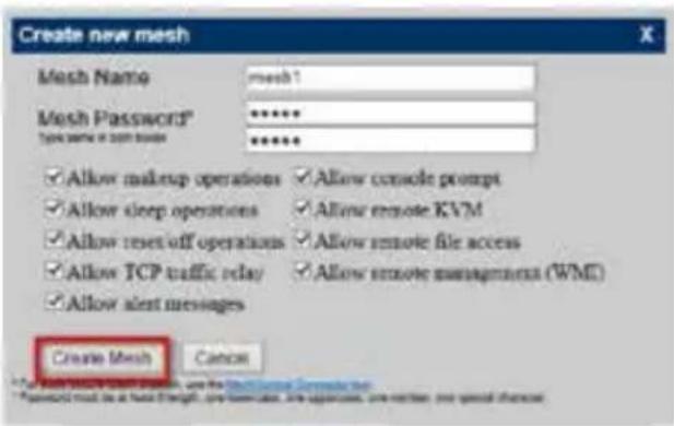
text_image
Create new mesh Mesh Name: mesh1 Mesh Password: ****** Type name or open browser ****** ✓ Allow makeup operations ✓ Allow console prompt ✓ Allow sleep operations ✓ Allow remote KVM ✓ Allow reset-off operations ✓ Allow remote file access ✓ Allow TCP traffic relay ✓ Allow remote management (WMI) ✓ Allow alert messages Create Mesh CancelDownloading and Installing Mesh Agent
Step 1
Click Install on the My Account page.

text_image
Add OpenID ? Google Yahoo! Administrative Meshes ( Manage New Install ) mesh1 Administrator rightsStep 2
Select the mesh and download both files. Make sure both files are in the same directory.
Step 3
Right-click on MeshAgent.exe and select Run as administrator.

text_image
Open Pin to Start Run as administrator Troubleshoot compatibility Share with Pin to Taskbar Send to Cut Copy Create shortcut Delete Rename PropertiesStep 4
Click Install / Update.
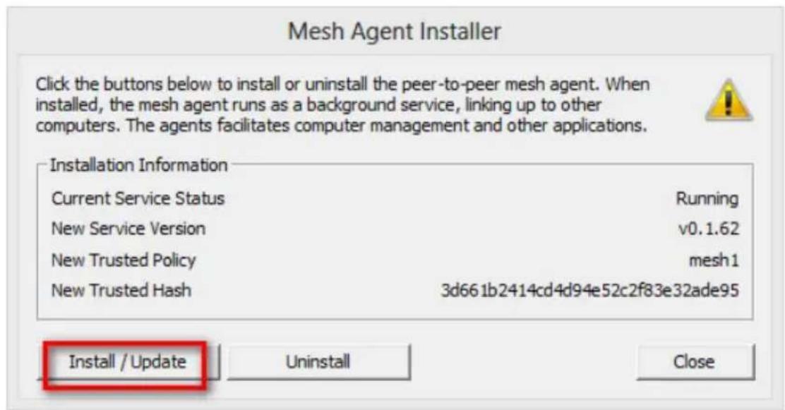
text_image
Mesh Agent Installer Click the buttons below to install or uninstall the peer-to-peer mesh agent. When installed, the mesh agent runs as a background service, linking up to other computers. The agents facilitates computer management and other applications. Installation Information Current Service Status Running New Service Version v0.1.62 New Trusted Policy mesh1 New Trusted Hash 3d661b2414cd4d94e52c2f83e32ade95 Install / Update Uninstall CloseStep 5
Wait a minute for the New Machine to appear in "My Device".
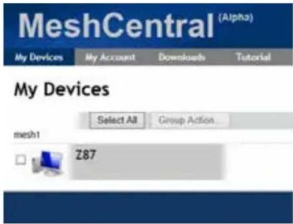
text_image
MeshCentral (Alpha) My Devices My Account Downloads Tutorial My Devices Select All Group Action... mesh1 Z87Step 6
Check whether "Intel Remote Wake" appeared or not.

text_image
MeshCentral (Alpha) My Devices General By Account Desktop Downloads Terminal Tutorial F SecZ87 - General
Mesh Name
Operating System
Mesh Agent
Extras
Power Actions
Audit Log

Microsoft® Windows 8
Wls32 Service v0.1.62
Intel® Remote Wake supported
Search
Waking up Your PC using PC
Step 1
On the "My Devices" page, click on Power Actions.
Step 2
Click on Wake or Sleep.
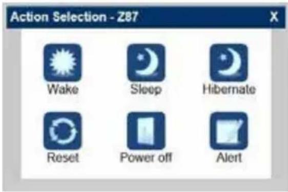
text_image
Action Selection - Z87 Wake Sleep Hibernate Reset Power off AlertWaking up Your PC Using Mobile Device

Before waking up your home computer using a mobile device, please log out of MeshCentral on other previously used computers or devices.
Step 1
Login to meshcentral.com/m.
Step 2
Select a Machine.
Step 3
Click on Wake or Sleep.

text_image
中華電信 3G 下午3:54 76% Mesh Management meshcentral.com/mob Search MESH Z87 Power on Action Selection Wake Sleep Hibernate Reset Power off Alert Computers Logout
text_image
QR code image containing encoded data, no visible human-readable textTutorial Video
5.6.2 Configuring and Using Splashtop
Splashtop is a remote desktop access software that lets you remotely access your home computer from your mobile device.
Before configuring this feature, verify that "Remote Wake" has been enabled in "Intel® Smart Connect Technology Manager".
Setup Guide
Step 1
Download and install the Streamer on your home computer, which is located in the folder at the following path of the Support CD: \ ASRock Utility > Splashtop Streamer. Then enter your Splashtop Account. If you have not created a Splashtop account, create one.
Step 2
Download and install "Splashtop 2" on your mobile device and log into the app.
Using Remote Wakeup
Step 1
In "Splashtop 2", tap the edit button next to an offline machine from the list.
Step 2
Tap "Wake up this computer".
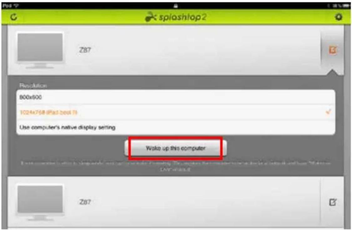
text_image
Z87 spia shtop2 Resolution 800x600 1024x768 @pst.best fi Use computer's native display setting Woke up this computer Z87Using Remote Control
Step 1
In "Splashtop 2", tap an online machine from the list to connect to your home computer.

text_image
WIN7SP1-PC Z87 Z87 ZT7EX6Step 2
Start remotely accessing your home computer.

The functionality and price of the Splashtop APP and subscription fee is subject to change. Please check www.splashtop.com for for details.
Accessing Data

text_image
Media Player(Win) Open Favorites Desktop Downloads Recent places Libraries Documents Music Pictures Views Computer Local Disk (C:) Local Disk (D:) Name Date month ago Splashbox Properties 1.79-01/13 1:00 Splashbox@whitobearl 1.79-01/13 1:00 File games Media Key (all types) Open CancelPlaying Video

natural_image
Forest scene with dense green bamboo grove and rocks, displayed in a blue media player interface (no text or symbols on the scene itself)5.7 Start8
For those Windows 8 users who miss the Start Menu, Start8 is an ideal solution that brings back the familiar Start Menu along with added customizations for greater efficiency.
5.7.1 Installing Start8
Install Start8, which is located in the folder at the following path of the Support CD: \ ASRock Utility > Start8.
5.7.2 Configuring Start8
Style
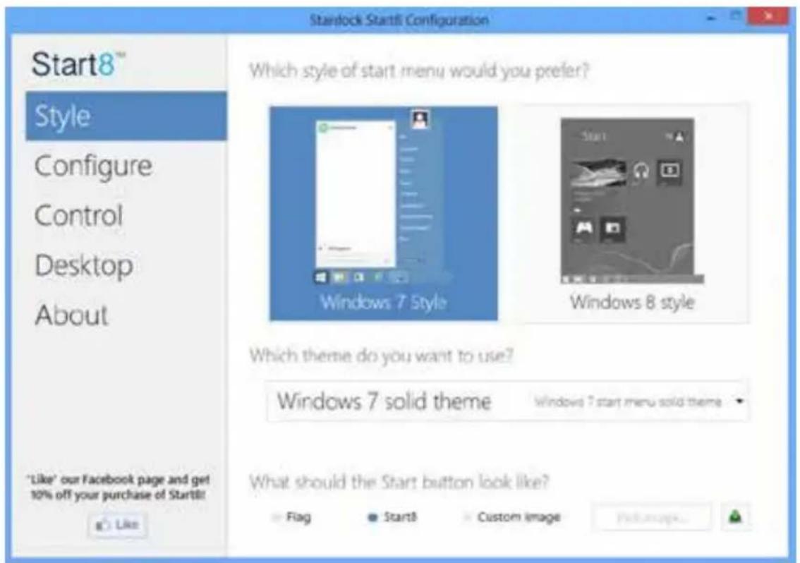
text_image
Starlock Start8 Configuration Which style of start menu would you prefer? Windows 7 Style Windows 8 style Which theme do you want to use? Windows 7 solid theme Windows 7 start menu solid theme What should the Start button look like? Flag Start8 Custom image Help me up... Like 'Like' our Facebook page and get 10% off your purchase of Start8!Select between the Windows 7 style and Windows 8 style Start Menu. Then select the theme of the Start Menu and customize the style of the Start icon.
Configure

text_image
Stardock Start8 Configuration Start8™ Style Configure Control Desktop About "Like" our Facebook page and get 10% off your purchase of Start3! Like What would you like to see on the menu? ✓ Use large icons ✓ Show recently used applications ✓ Open submenus when I pause on them with the mouse pointer ✓ Highlight newly installed applications Show user picture Allocate room for at least 10 large icons Which shortcuts do you want on the right hand side? Administrative Tools Computer Connect To Control Panel Default Programs Don't display this item Display as a link Don't display this item Display as a link Don't display this item Advanced... What should the power button do? Shut downConfigure provides configuration options, including icon sizes, which shortcuts you want Start Menu to display, quick access to recently used apps, the functionality of the power button, and more.
Control
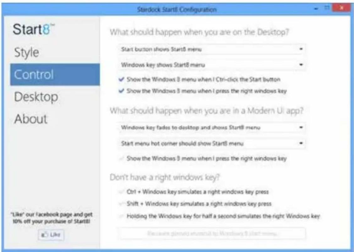
text_image
Start8™ Style Control Desktop About "Like" our Facebook page and get 10% off your purchase of Start8! a Like What should happen when you are on the Desktop? Start button shows Start8 menu Windows key shows Start8 menu ✓ Show the Windows 8 menu when I Ctrl-click the Start button ✓ Show the Windows 8 menu when I press the right windows key What should happen when you are in a Modern UI app? Windows key fades to desktop and shows Start8 menu Start menu hot corner should show Start8 menu ✓ Show the Windows 8 menu when I press the right windows key Don't have a right windows key? ✓ Ctrl + Windows key simulates a right windows key press ✓ Shift + Windows key simulates a right windows key press ✓ Holding the Windows key for half a second simulates the right Windows key Because planning what could to Windows 8 start menu.Control lets you configure what a click on the start button or a press on the Windows key does.
Desktop
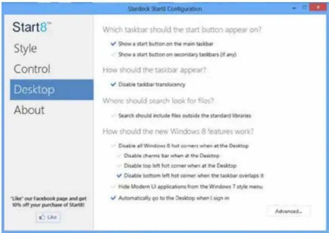
text_image
Start8™ Style Control Desktop About "Like" our Facebook page and get 10% off your purchase of Start8! Which taskbar should the start button appear on? ✓ Show a start button on the main taskbar ✓ Show a start button on secondary taskbars (if any) How should the taskbar appear? ✓ Disable taskbar translucency Where should search look for files? ✓ Search should include files outside the standard libraries How should the new Windows 8 features work? ✓ Disable all Windows 8 hot corners when at the Desktop ✓ Disable charms bar when at the Desktop- ✓ Disable top left hot corner when at the Desktop ✓ Disable bottom left hot corner when the taskbar overlaps it ✓ Hide Modern UI applications from the Windows 7 style menu ✓ Automatically go to the Desktop when I sign in Advanced...Desktop allows you to disable the hot corners when you are working on the desktop. It also lets you choose whether or not the system boots directly into desktop mode and bypass the Metro user interface.
About
Displays information about Start8.
5.8 XSplit Broadcaster
XSplit Broadcaster is a desktop application designed to make your gameplay broadcasting, live-streaming and recording a lot easier and more fun to do, we are giving away the 3 months premium license which is worth US\$24.95 for free!
5.8.1 Live Streaming Your Gameplay
Step 1
Go to Start > All Programs > XSplit > XSplit Broadcaster to launch it.

text_image
Catalyst Control Center CrystalDiscMark Futuremade Games Intel Intel Extreme Tuning Utility Intel® CablesMon Utility Maintenance Manvell Microsoft SQL Server 2008 Microsoft SQL Server 2012 Power Thermal Utility for Maxwell Proce RightMark Audio Analyzer SG Software Startup Windows Key XSplic Uninstall XSpilot Broadcaster XSpilot Broadcaster Release Notes XSpilot Broadcaster Back Tensions programs and filesStep 2
Log in with your own username and password. (If you do not have an XSplit account, click No XSplit account? to register.)

text_image
XSplit Email No XSplit accounts? Password Did you forget your password? Log On Remember me Log me in automatically English (United States) XSplit Core=1.2.1985.9101 Copyright © 2008-2019Step 3
Go to Broadcast > Add Channels....

text_image
XSplit Broadcaster File View Broadcast Announce Tools Help Local recording Add channels...Step 4
Click Add....

text_image
XSpin Broadcaster - User Settings Profile General Channels Revolutions Hotkeys If you have a membership with Twitch/Justin.tv, unstream.TV or another online service, you can add one or more channels for each service which supports open streaming via RTMP or RTMPT. Add... Edit... Remove Local recording OK Cancel ApplyStep 5
Select a platform for live streaming.
*Before you start streaming, you need to register an account for the streaming service website, such as Twitch.tv, USTREAM, or other livestreaming services.

text_image
XSplit Broadcaster - User Settings Profile General Channels Resolution Hotkeys If you have a membership with Twitch/Justin.io, ustream TV or another online service, you can add one or more channels for each service which supports open streaming via RTMP or RTMPT. have to have a new... Local streaming Custom RTMP Austin.io/Twitch Livestream USstream Local recording More... OK Cancel ApplyStep 6
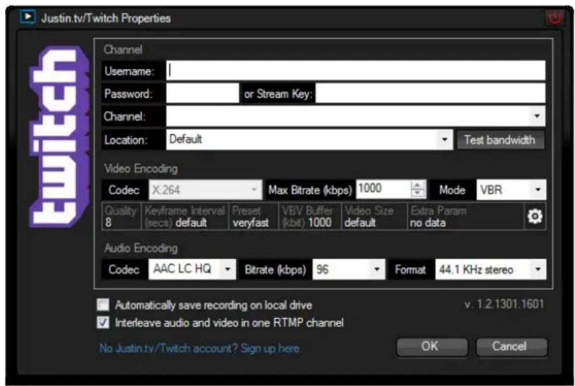
Fill in your platform's Username and Password.
Based on your needs, configure the Video and Audio Encoding settings. Click OK.
text_image
Justin.tv/Twitch Properties Channel Username: | Password: or Stream Key: Channel: Location: Default Test bandwidth Video Encoding Codec X.264 Max Bitrate (kbps) 1000 Mode VBR Quality Keyframe Interval Preset VBV Buffer Video Size Extra Param 8 (secs) default veryfast kbit 1000 default no data Audio Encoding Codec AAC LC HQ Bitrate (kbps) 96 Format 44.1 KHz stereo Automatically save recording on local drive v. 1.2.1301.1601 Interleave audio and video in one RTMP channel No Justin.tv/Twitch account? Sign up here. OK CancelStep 7
The channel then appears in your broadcast list. Click Apply and OK to save the settings.
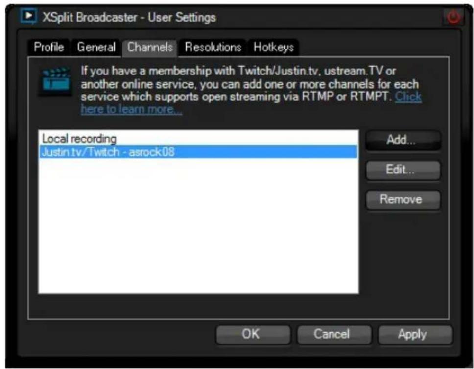
text_image
XSplit Broadcaster - User Settings Profile General Channels Resolutions Hotkeys If you have a membership with Twitch/Justin.tv, uptream.TV or another online service, you can add one or more channels for each service which supports open streaming via RTMP or RTMPT. Click here to learn more... Local recording Justin.tv/Twitch - asrock08 Add... Edit... Remove OK Cancel ApplyStep 8
Go to Broadcast and select the platform to enable live streaming.

text_image
File View Broadcast Announce Tools Help Justin.tv/Twitch - aurock08 Local recording Edit channels...A link to view your live Broadcast has been copied for you automatically. Simply press CTRL-V or right click and choose Paste to paste the link into the browser, and you can see your broadcast.
To disable live streaming, go to Broadcast again and deselect the platform.
5.7.2 Recording Your Gameplay
Step 1
Go to Broadcast > Local recording to start recording.

text_image
XSplit Broadcaster File View Broadcast Announce Tools Help Local recording Add channels...Step 2
To stop recording, Go to Broadcast again and deselect Local recording.
Step 3
Go to Tools > My Recordings...to access your recordings
Chapter 6 UEFI SETUP UTILITY
6.1 Introduction
ASRock Interactive UEFI is a blend of system configuration tools, cool sound effects and stunning visuals. Not only will it make BIOS setup less difficult but also a lot more amusing. This section explains how to use the UEFI SETUP UTILITY to configure your system. You may run the UEFI SETUP UTILITY by pressing right after you power on the computer, otherwise, the Power-On-Self-Test (POST) will continue with its test routines. If you wish to enter the UEFI SETUP UTILITY after POST, restart the system by pressing

Because the UEFI software is constantly being updated, the following UEFI setup screens and descriptions are for reference purpose only, and they may not exactly match what you see on your screen.
6.1.1 UEFI Menu Bar
The top of the screen has a menu bar with the following selections:
Main For setting system time/date information
OC Tweaker For overclocking configurations
Advanced For advanced system configurations
Tool Useful tools
H/W Monitor Displays current hardware status
Boot For configuring boot settings and boot priority
Security For security settings
Exit Exit the current screen or the UEFI Setup Utility
6.1.2 Navigation Keys
Use <←> key or <→> key to choose among the selections on the menu bar, and use <↑> key or <↓> key to move the cursor up or down to select items, then press
Please check the following table for the descriptions of each navigation key.
| Navigation Key(s) Description | |
| + / - | To change option for the selected items |
| Switch to next function | |
| Go to the previous page | |
| Go to the next page | |
| Go to the top of the screen | |
| Go to the bottom of the screen | |
| To display the General Help Screen | |
| Toggle sound on/off | |
| Discard changes and exit the SETUP UTILITY | |
| Load optimal default values for all the settings | |
| Save changes and exit the SETUP UTILITY | |
| Print screen | |
| Jump to the Exit Screen or exit the current screen | |
6.2 Main Screen
When you enter the UEFI SETUP UTILITY, the Main screen will appear and display the system overview.
text_image
ASRock UEFI Setup Utility Habit IE Tunknown Advanced Tools LINK POSITION Boot Secaritas Exit UIFI version : 280+ MB @1.04 Processor type : Desktop Core(75) CPU, 600 x 2.00KB Processor Speed : 280/MPB Processor Update : 300/0.7 Cache Size : 610/KB Total Power : 324MB actin 254MB Shared memory and 398 GTT among Single-Channel Memory Rock NOS_01 : 204/MB/204=15000 NOS_02 : None NETLAB Page PS Options NOS_01 Issue Get details file UK Open Key viewing Top 02/05/2022, 11:46:10Active Page on Entry
Select the default page when entering the UEFI setup utility.
UEFI Guide
UEFI Guide is a quick tutorial for ASRock's UEFI setup Utility. You may abort the tutorial by pressing "esc".
6.3 OC Tweaker Screen
In the OC Tweaker screen, you can set up overclocking features.
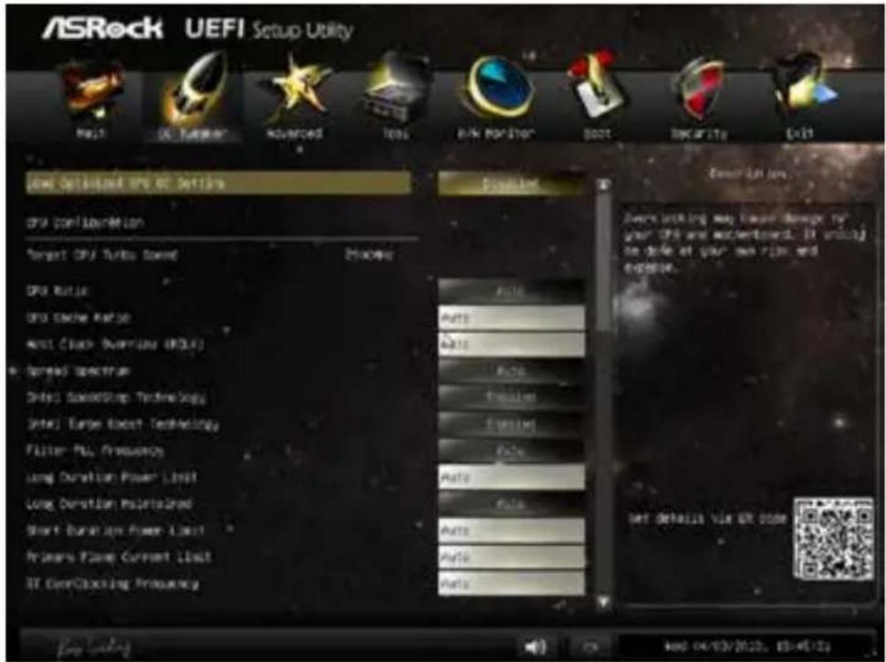
text_image
ASRock UEFI Setup Utility Auto Defaulted OPI:02 Settings CPU Configuration Target CPU Turbo Speed DPS Ratio DPS Cache Rate Max Clock Overview (RCLF) Spread Spectrum Data1 AudioStop Technology Intel1 Turbo Boost Technology Filter-PU Frequency Long Duration Power Limit Long Duration Maintained Short Duration Power Limit Primers Frame Current Limit ST ConClustering Frequency Auto Auto Auto Auto Auto Auto Auto Auto Auto Auto Auto Auto Auto Auto Auto Auto Auto Auto Auto Auto Auto Auto Auto Auto Auto Auto Auto Auto Auto Auto Auto Auto Auto Auto Auto Auto Auto Auto Auto Auto Auto Auto Auto Auto Auto Auto Auto Auto Auto Auto AUTO LTR Low Over working may lease damage for your OPI and accertment. It is only to close at your own risk and expense. Set Details Via OR code
Because the UEFI software is constantly being updated, the following UEFI setup screens and descriptions are for reference purpose only, and they may not exactly match what you see on your screen.
Load Optimized GPU OC Setting
You can use this option to load optimized GPU overclocking setting. Please note that overclocking may cause damage to your GPU and motherboard. It should be done at your own risk and expense. This option appears only when you adopt K-Series CPU.
CPU Configuration
CPU Ratio
The CPU speed is determined by the CPU Ratio multiplied with the BCLK. Increasing the CPU Ratio will increase the internal CPU clock speed without affecting the clock speed of other components.
CPU Cache Ratio
The CPU Internal Bus Speed Ratio. The maximum should be the same as the CPU Ratio.
BCLK/PCIE Frequency
The CPU speed is determined by the CPU Ratio multiplied with the BCLK.
Increasing the BCLK will increase the internal CPU clock speed but also affect the clock speed of other components.
Spread Spectrum
Enable Spread Spectrum to reduce electromagnetic interference for passing EMI tests. Disable to achieve higher clock speeds when overclocking.
Intel SpeedStep Technology
Intel SpeedStep technology allows processors to switch between multiple frequencies and voltage points for better power saving and heat dissipation.
Intel Turbo Boost Technology
Intel Turbo Boost Technology enables the processor to run above its base operating frequency when the operating system requests the highest performance state.
Filter PLL Frequency
CPU BCLK Filter Frequency. Choose 1.6 for better overclocking capabilities.
Long Duration Power Limit
Configure Package Power Limit 1 in watts. When the limit is exceeded, the CPU ratio will be lowered after a period of time. A lower limit can protect the CPU and save power, while a higher limit may improve performance.
Long Duration Maintained
Configure the period of time until the CPU ratio is lowered when the Long Duration Power Limit is exceeded.
Short Duration Power Limit
Configure Package Power Limit 2 in watts. When the limit is exceeded, the CPU ratio will be lowered immediately. A lower limit can protect the CPU and save power, while a higher limit may improve performance.
Primary Plane Current Limit
Configure the current limit of the CPU under Turbo Mode in ampere. A lower limit can protect the CPU and save power, while a higher limit may improve performance.
GT Frequency
Configure the frequency of the integrated GPU.
GT Voltage Mode
Auto: For optimized settings.
Adaptive: Add voltage to the integrated GPU when the system is under heavy load.
Override: The voltage is fixed.
GT Adaptive Voltage
Configure the fixed voltage added to the integrated GPU.
GT Voltage Offset
Configure the voltage added to the integrated GPU when the system is under heavy load.
DRAM Timing Configuration
DRAM Reference Clock
Select Auto for optimized settings.
DRAM Frequency
If [Auto] is selected, the motherboard will detect the memory module(s) inserted and assign the appropriate frequency automatically.
DRAM Configuration
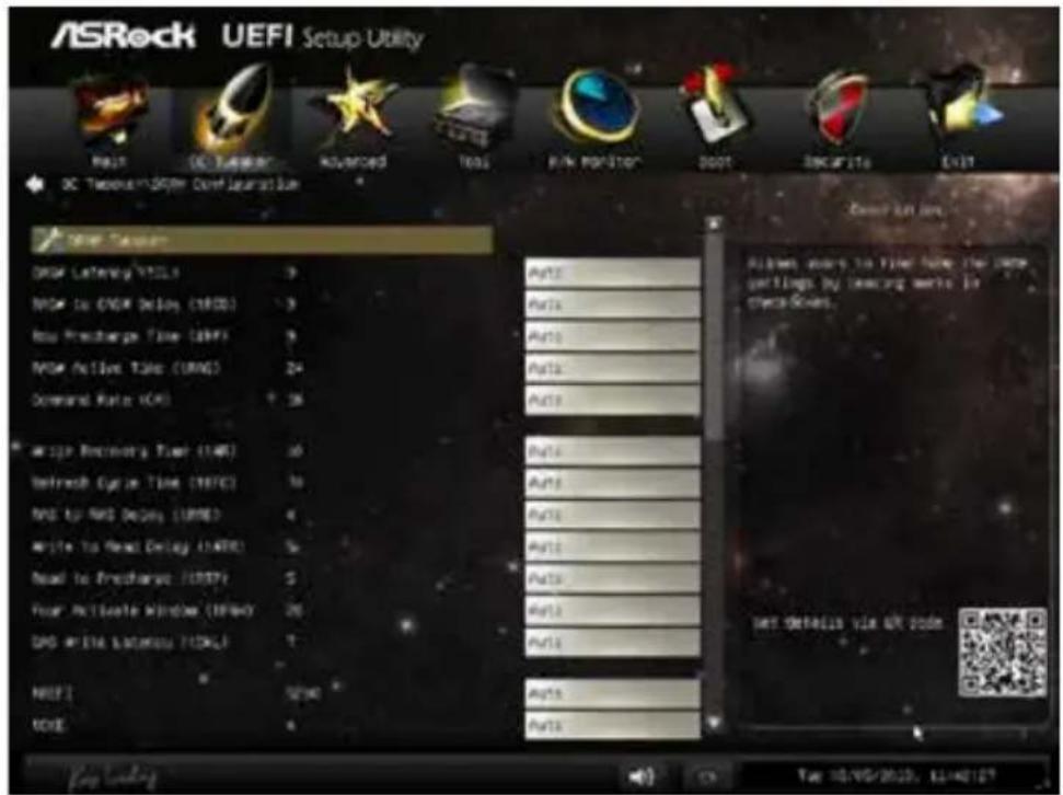
text_image
ASRock UEFI Setup Utility RMS DC Tension Advanced Test Pink Monitor boot SNCAPITs Exit DC Tension/SPER Control Installation NEW Tension DROM Latency (VTL) 3 MOS to COWI Delay (CWD) 3 Rus Precharge Time (RHP) 3 MOS Active Time (MRS) 24 Command Rate (CM) 16 Write Recovery Time (WR) 10 Refresh Cycle Time (HFC) 10 RND to RMS Delay (RWD) 4 Write to Read Delay (LATE) 5 Read to Precharge (REPI) 5 Pour Activate Window (EKEY) 26 DAD Write Latency (LCK) 7 NICE! 5290 CODE 4 Auto Auto Auto Auto Auto Auto Auto Auto Auto Auto Auto Auto Auto Auto Auto Auto Auto Auto Auto Auto Auto Auto Auto Auto Auto Auto Auto Auto Auto Auto Auto Auto Auto Auto Auto Auto Auto Auto Auto Auto Auto Auto Auto Auto Auto Auto Auto Auto Auto Auto AUTO 10/00/2013, 11:42:12? Key settings: AutoDRAM Tweaker
Fine tune the DRAM settings by leaving marks in checkboxes. Click OK to confirm and apply your new settings.
CAS# Latency (tCL)
The time between sending a column address to the memory and the beginning of the data in response.
RAS# to CAS# Delay (tRCD)
The number of clock cycles required between the opening of a row of memory and accessing columns within it.
Row Precharge Time (tRP)
The number of clock cycles required between the issuing of the precharge command and opening the next row.
RAS# Active Time (tRAS)
The number of clock cycles required between a bank active command and issuing the precharge command.
Command Rate (CR)
The delay between when a memory chip is selected and when the first active command can be issued.
Write Recovery Time (tWR)
The amount of delay that must elapse after the completion of a valid write operation, before an active bank can be precharged.
Refresh Cycle Time (tRFC)
The number of clocks from a Refresh command until the first Activate command to the same rank.
RAS to RAS Delay (tRRD)
The number of clocks between two rows activated in different banks of the same rank.
Write to Read Delay (tWTR)
The number of clocks between the last valid write operation and the next read command to the same internal bank.
Read to Precharge (tRTP)
The number of clocks that are inserted between a read command to a row pre-charge command to the same rank.
Four Activate Window (tFAW)
The time window in which four activates are allowed the same rank.
CAS Write Latency (tCWL)
Configure CAS Write Latency.
tREFI
Configure refresh cycles at an average periodic interval.
tCKE
Configure the period of time the DDR3 initiates a minimum of one refresh command internally once it enters Self-Refresh mode.
tRDRD
Configure between module read to read delay.
tRDRDDR
Configure between module read to read delay from different ranks.
tRDRDDD
Use this to change DRAM tRWSR Auto/Manual settings. The default is [Auto].
tWRRD
Configure between module write to read delay.
tWRRDDR
Configure between module write to read delay from different ranks.
tWRRDDD
Use this to change DRAM tRRSR Auto/Manual settings. The default is [Auto].
Configure between module write to read delay from different DIMMs.
tWRWR
Configure between module write to write delay.
tWRWRDR
Configure between module write to write delay from different ranks.
tWRWRDD
Configure between module write to write delay from different DIMMs.
tRDWR
Configure between module read to write delay.
tRDWRDR
Configure between module read to write delay from different ranks.
tRDWRDD
Configure between module read to write delay from different DIMMs.
RTL (CHA)
Configure round trip latency for channel A.
RTL (CHB)
Configure round trip latency for channel B.
IO-L (CHA)
Configure IO latency for channel A.
IO-L (CHB)
Configure IO latency for channel B.
ODT WR (CHA)
Configure the memory on die termination resistors' WR for channel A.
ODT WR (CHB)
Configure the memory on die termination resistors' WR for channel B.
ODT NOM (CHA)
Use this to change ODT (CHA) Auto/Manual settings. The default is [Auto].
ODT NOM (CHB)
Use this to change ODT (CHB) Auto/Manual settings. The default is [Auto].
Command Tri State
Enable for DRAM power saving.
MRC Fast Boot
Enable Memory Fast Boot to skip DRAM memory training for booting faster.
FIVR Configuration
FIVR Switch Frequency Signature
Select whether to boost or lower the FIVR Switch Frequency.
FIVR Switch Frequency Offset
Configure the percentage of frequency boost or deduction.
CPU Voltage Mode
Auto: For optimized settings.
Adaptive: Add voltage to the CPU when the system is under heavy load.
Override: The voltage is fixed.
CPU Override Voltage
Configure the voltage added to the CPU when the system is under heavy load.
CPU Voltage Offset
Configure the dynamic CPU voltage added to the CPU.
CPU Cache Override Voltage
Add voltage to the CPU Cache when the system is under heavy load.
CPU Cache Adaptive Voltage
Configure the voltage added to the CPU Cache when the system is under heavy load.
CPU Cache Voltage Offset
Configure the voltage for the CPU Cache. Setting the voltage higher may increase system stability when overclocking.
System Agent Voltage Offset
Configure the voltage for the System Agent. Setting the voltage higher may increase system stability when overclocking.
CPU Analog IO Voltage Offset
CPU I/O Analog Voltage.
CPU Digital IO Voltage Offset
CPU I/O Digital Voltage.
CPU Integrated VR Faults
Disable FIVR Faults to raise the threshold to trigger CPU over current protection and over voltage protection for better overclocking capabilities.
CPU Integrated VR Efficiency Mode
Enable FIVR Efficiency Management for power saving. Disable for better performance and overclocking capabilities.
Voltage Configuration
CPU Input Voltage
Configure the voltage for the CPU.
CPU Load-Line Calibration
CPU Load-Line Calibration helps prevent CPU voltage droop when the system is under heavy load.
VCORE External Offset
The fixed external voltage input to the CPU.
DRAM Voltage
Use this to configure DRAM Voltage. The default value is [Auto].
PCH 1.05V Voltage
Chipset 1.05V Voltage. Use default settings for best performance.
PCH 1.5V Voltage
I/O 1.5V Voltage. Use default settings for best performance.
6.4 Advanced Screen
In this section, you may set the configurations for the following items: CPU Configuration, Chipset Configuration, Storage Configuration, Intel® Rapid Start Technology, Intel® Smart Connect Technology, ACPI Configuration and USB Configuration.

text_image
ASRock UEFI Setup Utility Menu OK Tukeyer Advanced Tools Risk Monitor Boot Scaritas Exit OPS Configuration Dropout Configuration Startset Configuration Delphi(R) Reald Short Technology Dial(K) Start Connect Technologies ADPC Configuration Auto Configuration Delete Run Only OPS Configuration Parameters Get Details VIA OR CODE Key viewing Sun 10/05/2013, 12:46:58
Setting wrong values in this section may cause the system to malfunction.
6.4.1 CPU Configuration

text_image
ASRock UEFI Setup Utility Default: Complete CPU 3000.0-2.0000 Max CPU Speed Min CPU Speed Processor Rate Finite MT Technologies Finite VT x Technologies Finite DB Technologies 64-SU7 System Performance Status CPU C Status Support Enabled Mode ShareCES CPU D Share Support CPU D Share Support CPU D Share Support Package C Status Support CPU Thermal Transmission No-Exposure Memory Protection Finite Virtualization Technologies Auto Auto Auto Auto Auto Auto Auto Auto Auto Auto Auto Auto Auto Auto Auto Auto Auto Auto Auto Auto Auto Auto Auto Auto Auto Auto Auto Auto Auto Auto Auto Auto Auto Auto Auto Auto Auto Auto Auto Auto Auto Auto Auto Auto Auto Auto Auto Auto Auto Auto AUTO AUTO AUTO AUTOActive Processor Cores
Select the number of cores to enable in each processor package.
CPU C States Support
Enable CPU C States Support for power saving. It is recommended to keep C3, C6 and C7 all enabled for better power saving.
Enhanced Halt State (C1E)
Enable Enhanced Halt State (C1E) for lower power consumption.
CPU C3 State Support
Enable C3 sleep state for lower power consumption.
CPU C6 State Support
Enable C6 deep sleep state for lower power consumption.
CPU C7 State Support
Enable C7 deep sleep state for lower power consumption.
Package C State Support
Enable CPU, PCIe, Memory, Graphics C State Support for power saving.
CPU Thermal Throttling
Enable CPU internal thermal control mechanisms to keep the CPU from overheating.
No-Execute Memory Protection
Processors with No-Execution Memory Protection Technology may prevent certain classes of malicious buffer overflow attacks.
Intel Virtualization Technology
Intel Virtualization Technology allows a platform to run multiple operating systems and applications in independent partitions, so that one computer system can function as multiple virtual systems.
Hardware Prefetcher
Automatically prefetch data and code for the processor. Enable for better performance.
Adjacent Cache Line Prefetch
Automatically prefetch the subsequent cache line while retrieving the currently requested cache line. Enable for better performance.
6.4.2 Chipset Configuration
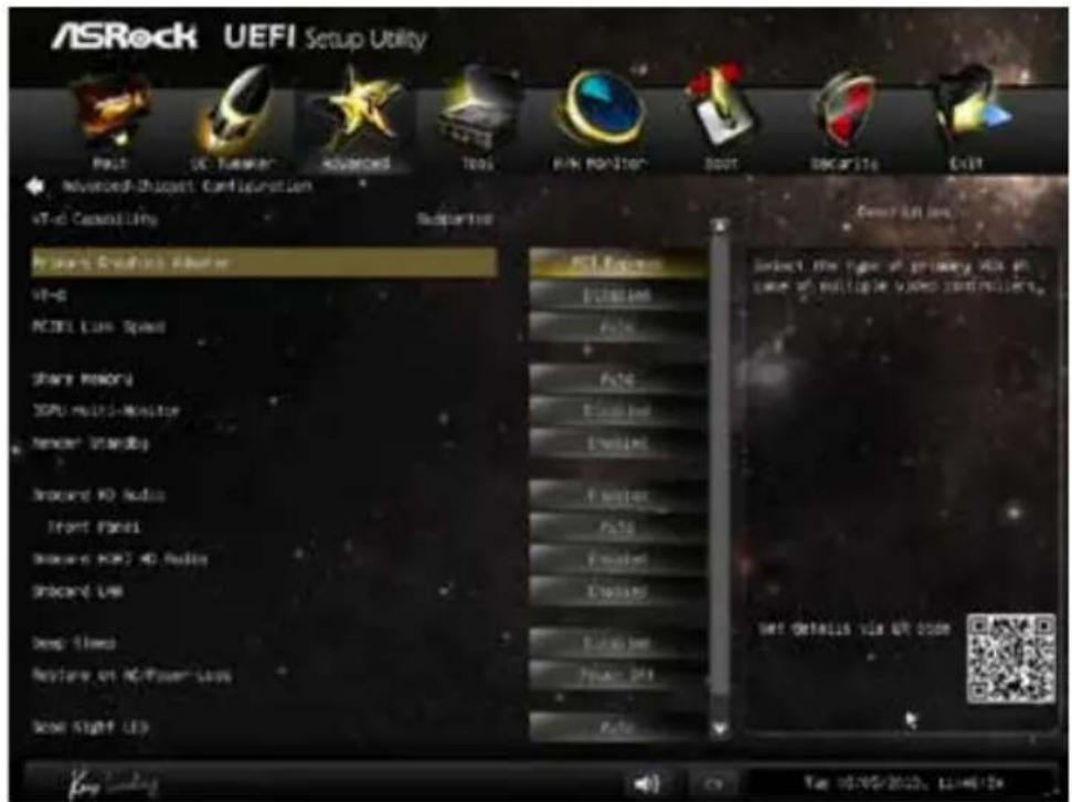
text_image
ASRock UEFI Setup Utility Paul UC Funower Advanced Tools WIN MONITOR Boot Decarito Exit Advanced-Boost Configuration VR-6 Control LIFO Supported Virtual Real-time Analyzer VR-G PCCEL Live Speed Share Memory SDPU Multi-Monitor Monitor 300000 Record ID Audio Front Panel Record RGB 4D Audio Record USB Deep Slows Restore on PC/Flower-Says Show Light LED PCI Features Dissipation Failure Failure Exhausted Exhausted Failure Failure Exhausted Exhausted Power OFF Power OFF Select the type of primary VDS at case of multiple video controllers. SET DETAILS VIA VR CODEPrimary Graphics Adapter
Select a primary VGA.
VT-d
Intel® Virtualization Technology for Directed I/O helps your virtual machine monitor better utilize hardware by improving application compatibility and reliability, and providing additional levels of manageability, security, isolation, and I/O performance.
PCIE1 Link Speed
Select the link speed for PCIE1.
Share Memory
Configure the size of memory that is allocated to the integrated graphics processor when the system boots up.
IGPU Multi-Monitor
Select disable to disable the integrated graphics when an external graphics card is installed. Select enable to keep the integrated graphics enabled at all times.
Render Standby
Power down the render unit when the GPU is idle for lower power consumption.
Onboard HD Audio
Enable/disable onboard HD audio. Set to Auto to enable onboard HD audio and automatically disable it when a sound card is installed.
Front Panel
Enable/disable front panel HD audio.
Onboard HDMI HD Audio
Enable audio for the onboard digital outputs.
Onboard LAN
Enable or disable the onboard network interface controller.
Deep Sleep
Configure deep sleep mode for power saving when the computer is shut down.
Restore on AC/Power Loss
Select the power state after a power failure. If [Power Off] is selected, the power will remain off when the power recovers. If [Power On] is selected, the system will start to boot up when the power recovers.
Good Night LED
By enabling Good Night LED, the Power/HDD LEDs will be switched off when the system is on. It will also automatically switch off the Power and Keyboard LEDs when the system enters into Standby/Hibernation mode.
WAN1 Radio
Enable/disable the WiFi module's connectivity.
6.4.3 Storage Configuration

text_image
ASRock UEFI Setup Utility Main Advanced Advanced Tools Network Monitor Boot Security Auto Advanced-Storage Configuration MSTR Controller for MSTR mode Selection MSTR Advanced/Slow Power Management Dynamic Storage Desorption Word OSS 3.P.A.R.7 SVMOS_1 SVMOS_2 SVMOS_3 SVMOS_4 SVMOS_S/E/SVMOS SVMOS_1 Not Detected SVMOS_2 Not Detected SVMOS_3 Not Detected SVMOS_4 Not Detected SVMOS_S/E/SVMOS = Not Detected Enrolled View 0 Enrolled Enrolled Enrolled End to all the MSTR Devices. NET DETAILS VIA OK DOWN OK ON/OFF/2013, 15:46:44SATA Controller(s)
Enable/disable the SATA controllers.
SATA Mode Selection
IDE: For better compatibility.
AHCI: Supports new features that improve performance.
RAID: Combine multiple disk drives into a logical unit.

AHCI (Advanced Host Controller Interface) supports NCQ and other new features that will improve SATA disk performance but IDE mode does not have these advantages.
SATA Aggressive Link Power Management
SATA Aggressive Link Power Management allows SATA devices to enter a low power state during periods of inactivity to save power. It is only supported by AHCI mode.
Dynamic Storage Accelerator
Keep this option enabled for higher HDD and SDD I/O performance, lower latency and increased system responsiveness.
Hard Disk S.M.A.R.T.
S.M.A.R.T stands for Self-Monitoring, Analysis, and Reporting Technology. It is a monitoring system for computer hard disk drives to detect and report on various indicators of reliability.
6.4.4 Intel® Rapid Start Technology
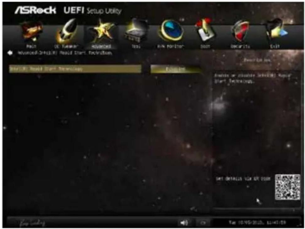
text_image
ASRock UEFI Setup Utility Make DE: Turnover Advanced Tools RANK POSITION DOOT DECAPITs Exit Advanced:UEFI Would Start Technologies Options Details or private UEFI Would Start Technologies. SET DETAILS VIA EUR DOWN File Edit View Help Tools Help Settings Help Options Help Settings Help Options Help Settings Help Options Help Settings Help Options Help Settings Help Options Help Settings Help Options Help Settings Help Options Help Settings Help Options Help Settings Help Options Help Settings Help Options Help Settings Help Options Help Settings Help Options Help Settings Help Options Help Settings Help Options Help Settings Help Options Help Settings Help Options Help Settings Help Options Help Settings Help Options Help Settings Help Options Help Settings Help Options Help Settings Help Options Help Settings Help Options Help Settings Help Options Help Settings Help Options Help Settings Help Options Help Settings Help Types Help Settings Help Settings Help Settings Help Settings Help Settings Help Settings Help Settings Help Settings Help Settings Help Settings Help Settings Help Settings Help Settings Help Settings Help Settings Help Settings Help Settings Help Settings Help Settings Help Settings Help Settings Help Settings Help Settings Help Settings Help Settings Help Settings Help Settings Help Settings Help Settings Help Settings Help Settings Help Settings Help Settings Help Settings Help Settings Help Settings Help Settings Help Settings Help Settings Help Settings Help Settings Help Settings Help Settings Help Settings Help Settings Help Settings Help Settings Help Settings Help Settings Help Settings Help Sections Help Settings Help Settings Help Settings Help Settings Help Settings Help Settings Help Settings Help Settings Help Settings Help Settings Help Settings Help Settings Help Settings Help Settings Help Settings Help Settings Help Settings Help Settings Help Settings Help Settings Help Settings Help Settings Help Settings Help Settings Help Settings Help Settings Help Settings Help Settings Help Settings Help Settings Help Settings Help Settings Help Settings Help Settings Help Settings Help Settings Help Settings Help Settings Help Settings Help Settings Help Settings Help Settings Help Settings Help Settings Help Settings Help Settings Help Settings Help Settings Help Settings Help Conditions OK Cancel Stop Cancel Stop Help Options Help Details Help Details Help Details Help Details Help Details Help Details Help Details Help Details Help Details Help Details Help Details Help Details Help Details Help Details Help Details Help Details Help Details Help Details Help Details Help Details Help Details Help Details Help Details Help Details Help Details Help Details Help Details Help Details Help Details Help Details Help Details Help Details Help Details Help DetailsIntel® Rapid Start Technology
Intel® Rapid Start Technology is a new zero power hibernation mode which allows users to resume in just 5-6 seconds.
6.4.5 Intel® Smart Connect Technology
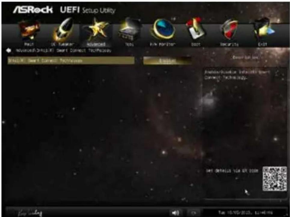
text_image
ASRock UEFI Setup Utility Next > 2013/05/2023, 12:46:19 Advanced UEFI (X) Smart Connect Technicals UEFI (X) Smart Connect Technicals Options Smart Connect Smart Connect Technicals Set default via UR 2023 Get default via UR 2023 Get default via UR 2023Intel® Smart Connect Technology
Intel® Smart Connect Technology automatically updates your email and social networks, such as Twitter, Facebook, etc. while the computer is in sleep mode.
6.4.6 ACPI Configuration
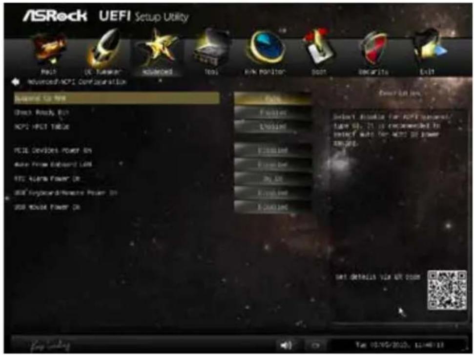
text_image
ASRock UEFI Setup Utility MOSI UC-Turnor Risplanced Tools RINK Position Spot SNCARITA Exit Advanced NCPI Configuration Standard to Use Check Ready Out NCPI MSCI TRES PDE Devices Power On Drive From Board LAM RTC Alaska Power On USB Keyboard/Reserve Power On USB Audio Power On Fines LPG100 Fines Power One My One Rout One S-Cutions Description: Select Altless for NCPI personnel. Type 58, 25 is recommended to select auto for NCPI power on the Set Details via AR zoomSuspend to RAM
Select disable for ACPI suspend type S1. It is recommended to select auto for ACPI S3 power saving.
Check Ready Bit
Enable to enter the operating system after S3 only when the hard disk is ready, this is recommended for better system stability.
ACPI HPET Table
Enable the High Precision Event Timer for better performance and to pass WHQL tests.
PCIE Devices Power On
Allow the system to be waked up by a PCI device and enable wake on LAN.
Wake From Onboard LAN
Allow the system to be waked up by the Onboard Intel I217V LAN.
RTC Alarm Power On
Allow the system to be waked up by the real time clock alarm. Set it to By OS to let it be handled by your operating system.
USB Keyboard/Remote Power On
Allow the system to be waked up by an USB keyboard or remote controller.
USB Mouse Power On
Allow the system to be waked up by an USB mouse.
6.4.7 USB Configuration
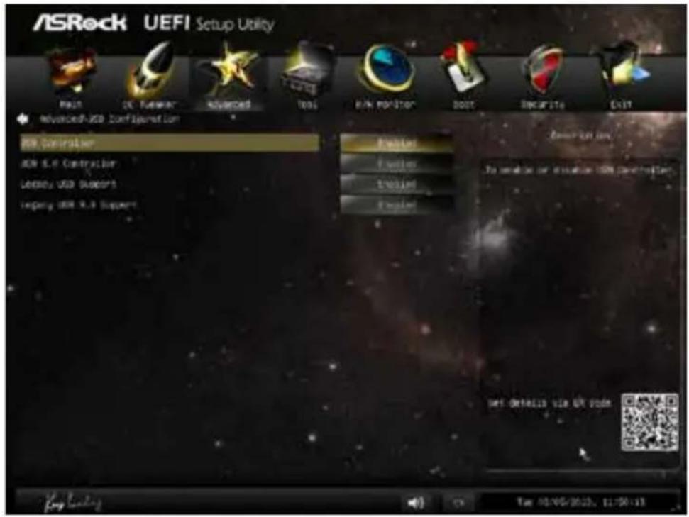
text_image
ASRock UEFI Setup Utility Main DC Follower Advanced Tools RUN POSTOR BOOT SINGFITE OUT advanced-USD Configuration USB Controller USB 5.0 Controller Latency USB Subopt Legacy USB 5.0 Support Provider Provider Provider Provider Description To avoid or avoid the USN configuration NET Otitelis file UP Power Log loading Fax: 02-95-2623, 11:50:13USB Controller
Enable or disable all the USB ports.
USB 3.0 Controller
Enable or disable all the USB 3.0 ports.
Legacy USB Support
Enable or disable Legacy OS Support for USB 2.0 devices. If you encounter USB compatibility issues it is recommended to disable legacy USB support. Select UEFI Setup Only to support USB devices under the UEFI setup and Windows/Linux operating systems only.
Legacy USB 3.0 Support
Enable or disable Legacy OS Support for USB 3.0 devices.
6.5 Tools

text_image
ASRock UEFI Setup Utility Next User Forward Advanced Web R-N Position Boot Binar10 Exit Options Driver OK Online Management Award UIFI Tech Services Easy PID Sortsion RPT Update Utility Instant Flash Internet Flash = DXP (Auto 3"), Google Network Configuration Demand/Per Function Allow non LDP to save current getting as user defaults? Save lost user default User Default 0 Save lost user default User default 0 Set Defaults via OR option Log loading Fax 05/05/2023, 11:31:28System Browser
ASRock System Browser shows the overview of your current PC and the devices connected.
OMG (Online Management Guard)
Administrators are able to establish an internet curfew or restrict internet access at specified times via OMG. You may schedule the starting and ending hours of internet access granted to other users. In order to prevent users from bypassing OMG, guest accounts without permission to modify the system time are required.
UEFI Tech Service
Contact ASRock Tech Service if you are having trouble with your PC. Please setup network configuration before using UEFI Tech Service.
Easy RAID Installer
Easy RAID Installer helps you to copy the RAID driver from the support CD to your USB storage device. After copying the drivers please change the SATA mode to RAID, then you can start installing the operating system in RAID mode.
Easy Driver Installer
For users that don't have an optical disk drive to install the drivers from our support CD, Easy Driver Installer is a handy tool in the UEFI that installs the LAN driver to your system via an USB storage device, then downloads and installs the other required drivers automatically.
Instant Flash
Save UEFI files in your USB storage device and run Instant Flash to update your UEFI.
Internet Flash
ASRock Internet Flash downloads and updates the latest UEFI firmware version from our servers for you. Please setup network configuration before using Internet Flash.
*For BIOS backup and recovery purpose, it is recommended to plug in your USB pen drive before using this function.
Network Configuration
Use this to configure internet connection settings for Internet Flash.

text_image
ASRock UEFI Setup Utility Multi OS Networks Advanced Tools Monitor Smart Internet Status MPT Download Service SET details via QR code Key loading Get 04/05/2018, 0:36:21Internet Setting
Enable or disable sound effects in the setup utility.
UEFI Download Server
Select a server to download the UEFI firmware.
Dehumidifier Function
If Dehumidifier Function is enabled, the computer will power on automatically to dehumidify the system after entering S4/S5 state.
Dehumidifier Period
Configure the period of time until the computer powers on and enables Dehumidifier after entering S4/S5 state.
Dehumidifier Duration
Configure the duration of the dehumidifying process before it returns to S4/S5 state.
Dehumidifier CPU Fan Setting
Configure the speed of the CPU fan while Dehumidifier is enabled. The higher the value, the faster the fan speed.
Max: 255
Min: 1
Save User Default
Type a profile name and press enter to save your settings as user default.
Load User Default
Load previously saved user defaults.
6.6 Hardware Health Event Monitoring Screen
This section allows you to monitor the status of the hardware on your system, including the parameters of the CPU temperature, motherboard temperature, fan speed and voltage.
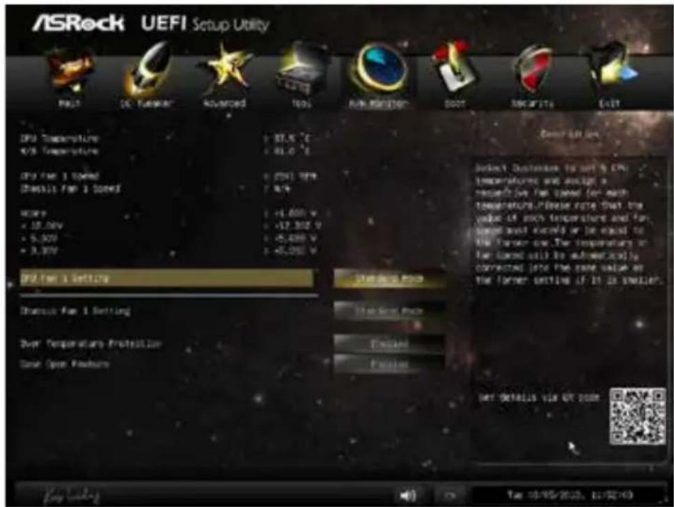
text_image
ASRock UEFI Setup Utility RMS DC Power Advanced Tools RUN MONITOR BOOT SECURITY EXIT CPU Temperature 87.5 °C 81.0 °C CPU Fan 1 Rated 2041.99% 8/9 HKEY +1,000 V +12,302 V +5,400 V +5,000 V CPU Fan 2 Setting Reset Fan 1 Setting Over Temperature Protection Save Open Feature Reset Fan 2 Setting Reset Fan 1 Setting Reset Fan 1 Setting Reset Fan 1 Setting Reset Fan 1 Setting Reset Fan 1 Setting Reset Fan 1 Setting Reset Fan 1 Setting Reset Fan 1 Setting Reset Fan 1 Setting Reset Fan 1 Setting Reset Fan 1 Setting Reset Fan 1 Setting Reset Fan 1 Setting Reset Fan 1 Setting Reset Fan 1 Setting Reset Fan 1 Setting Reset Fan 1 Setting Reset fan setting of CPU temperature and output a respective fan speed for each temperature. Please note that the value of such temperature and fan speed and output or be equal to the former one. The temperature or fan speed will be automatically corrected into the same value at the former setting if it is smaller. Reset fan setting of CPU temperature and output a respective fan speed for each temperature. Please note that the value of such temperature and fan speed and output or be equal to the former one. The temperature or fan speed will be automatically corrected into the same value at the former setting if it is smaller. Reset fan setting of CPU temperature and output a respective fan speed for each temperature. Please note that the value of such temperature and fan speed and output or be equal to the former one. The temperature or nanorated output is not necessarily corrected into the former setting if it is smaller. Reset fan setting of CPU temperature and output a respective fan speed for each temperature. Please note that the value of such temperature and fan speed and output or be equal to the former one. The temperature or nanorated output is not necessarily corrected into the former setting if it is smaller. Reset fan setting of CPU temperature and output a respective fan speed for each temperature. Please note that the value of such temperature and fan speed and output or be equal to the first corner. The temperature or nanorated output is not necessarily corrected into the former setting if it is smaller. Reset fan setting of CPU temperature and output a respective fan speed for each temperature. Please note that the value of such temperature and fan speed and output or be equal to the first corner. The temperature or nanorated output is not necessarily corrected into the former setting if it is smaller. Reset fan setting of CPU temperature and output a respective fan speed for each temperature. Please note that the value is not necessarily corrected into the former setting if it is smaller. Reset fan setting of CPU temperature and output a respective fan speed for each temperature. Please note that the value is not necessarily corrected into the former setting if it is smaller. Reset fan setting of CPU temperature and output a respective fan speed for each temperature. Please note that the value is not necessarily corrected into the former setting if it is smaller. Reset fan setting of CPU temperature and output a respective fan speed for each temperature. Please note which the value is not necessarily corrected into the former setting if it is smaller. Reset fan setting of CPU temperature and output a respective fan speed for each temperature. Please note that the value is not necessarily corrected into the former setting if it is smaller. Reset fan setting of CPU temperature and output a respective fan speed for each temperature. Please note that the value is not necessarily corrected into the former setting if it is smaller. Reset fan setting of CPU temperature and output a respective fan speed for each temperature. please note that the value is not necessarily corrected into the former setting if it is smaller. Reset fan setting of CPU temperature and output a respective fan speed for each temperature. Please note that the value is not necessarily corrected into the former setting if it is smaller. Reset fan setting of CPU temperature and output a respective fan speed for each temperature. Please note that the value is not necessarily corrected into the former setting if it is smaller. Reset fan setting of CPU temperature and output a respective fan speed for each temperatures. Please note that the value is not necessarily corrected into the former setting if it is smaller. Reset fan setting of CPU temperature and output a respective fan speed for each temperature. Please note that the value is not necessarily corrected into the former setting if it is smaller. Reset fan setting of CPU temperature and output a respective fan speed for each temperature. Please note that the value is not necessarily corrected into the former setting if it is smaller. Reset fan setting of CPU temperature and output a respective fan speedfor their respective values are not currently available.CPU Fan 1 Setting
Select a fan mode for CPU Fans 1, or choose Customize to set 5 CPU temperatures and assign a respective fan speed for each temperature.
Chassis Fan 1 Setting
Select a fan mode for Chassis Fan 1, or choose Customize to set 5 CPU temperatures and assign a respective fan speed for each temperature.
Over Temperature Protection
When Over Temperature Protection is enabled, the system automatically shuts down when the motherboard is overheated.
Case Open Feature
Enable or disable Case Open Feature to detect whether the chassis cover has been removed.
6.7 Boot Screen
This section displays the available devices on your system for you to configure the boot settings and the boot priority.
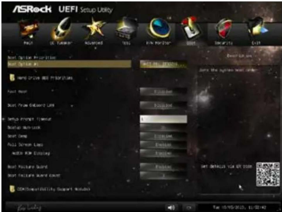
text_image
ASRock UEFI Setup Utility Next Option Properties Next Option #1 Hand Drive Our Priorities Next Door Next Phone Connection Line Setup Internet Provider Backup Systemlock Next Open Next Screen Lasso Adder RIM Display Next Package Board Next Package Sound Count CDM Support/Fall Supply (Suppli Module) Next Roll Status... Set the system next order Set defaults via OK state Top 10/05/2013, 11/27:42Fast Boot
Fast Boot minimizes your computer's boot time. In fast mode you may not boot from an USB storage device. Ultra Fast mode is only supported by Windows 8 and the VBIOS must support UEFI GOP if you are using an external graphics card. Please notice that Ultra Fast mode will boot so fast that the only way to enter this UEFI Setup Utility is to Clear CMOS or run the Restart to UEFI utility in Windows.
Boot From Onboard LAN
Allow the system to be waked up by the onboard LAN.
Setup Prompt Timeout
Configure the number of seconds to wait for the setup hot key.
Bootup Num-Lock
Select whether Num Lock should be turned on or off when the system boots up.
Boot Beep
Select whether the Boot Beep should be turned on or off when the system boots up. Please note that a buzzer is needed.
Full Screen Logo
Enable to display the boot logo or disable to show normal POST messages.
AddOn ROM Display
Enable AddOn ROM Display to see the AddOn ROM messages or configure the AddOn ROM if you've enabled Full Screen Logo. Disable for faster boot speed.
Boot Failure Guard
If the computer fails to boot for a number of times the system automatically restores the default settings.
Boot Failure Guard Count
Configure the number of attempts to boot until the system automatically restores the default settings.
CSM (Compatibility Support Module)
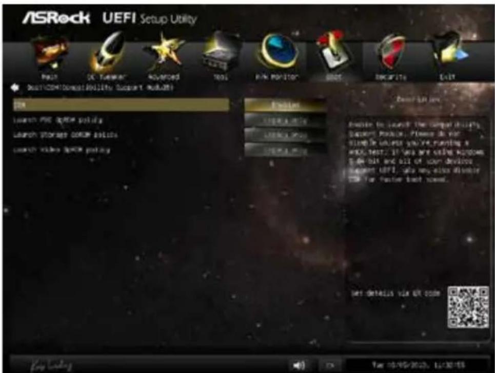
text_image
ASRock UEFI Setup Utility Help OK Tuwear Advanced Tools RANK POSITION GROSE DECARITY EXIT DOYCOMPUTability Support Utilities ON Launch PDF OPEM Policy Launch Storage COME Policy Launch Video COME Policy Options Create Active Create Active Create Active Power Bar key Options to launch the compact utility's Docker Module. Please do your Slowte universe you're running a WELL TEST? If you are using Windows 5 or 10% and all of your devices support UEFI, also may alter disable T28 for faster boot novel. Get details via QR code Key settings OK Cancel Take 10/05/2023, Limit ToolsCSM
Enable to launch the Compatibility Support Module. Please do not disable unless you're running a WHCK test. If you are using Windows 8 64-bit and all of your devices support UEFI, you may also disable CSM for faster boot speed.
Launch PXE OpROM Policy
Select UEFI only to run those that support UEFI option ROM only. Select Legacy only to run those that support legacy option ROM only. Do not launch?
Launch Storage OpROM Policy
Select UEFI only to run those that support UEFI option ROM only. Select Legacy only to run those that support legacy option ROM only. Do not launch?
Launch Video OpROM Policy
Select UEFI only to run those that support UEFI option ROM only. Select Legacy only to run those that support legacy option ROM only. Do not launch?
6.8 Security Screen
In this section you may set or change the supervisor/user password for the system. You may also clear the user password.
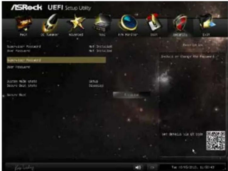
text_image
ASRock UEFI Setup Utility Multi DC Tumor Advanced Tools RAIN POSITION BOOT DISCAPS LIST Supervision Password Net Installation Boot Features Net Installation Supervision Password Boot Features Auto NSK State Setup Secure Boot State Displacement Secure Boot Create Get details via OR code Key loading Tag 10/05/2023, 12:00:43Supervisor Password
Set or change the password for the administrator account. Only the administrator has authority to change the settings in the UEFI Setup Utility. Leave it blank and press enter to remove the password.
User Password
Set or change the password for the user account. Users are unable to change the settings in the UEFI Setup Utility. Leave it blank and press enter to remove the password.
Secure Boot
Enable to support Windows 8 Secure Boot.
6.9 Exit Screen
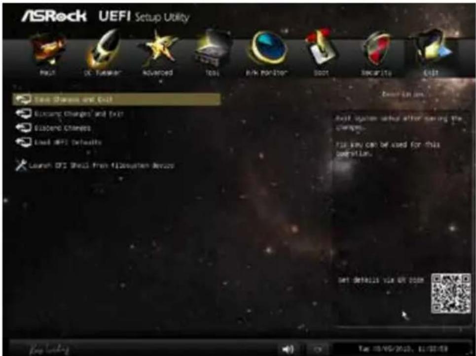
text_image
ASRock UEFI Setup Utility Help OK Tender Advanced Tools Risk Monitor Boot Security Edit Test Sharms and Chill Discount Charges and Exit Suspend Charges Load UP2 Defaults Launch UP2 Shell from 1120x40mm Breaks Next Launch on: Next system starts after saving the changes. This key can be used for this version. Set details via OR zoom Keep working Take 10/05/2013, 11:22:18Save Changes and Exit
When you select this option the following message, "Save configuration changes and exit setup?" will pop out. Select [OK] to save changes and exit the UEFI SETUP UTILITY.
Discard Changes and Exit
When you select this option the following message, “Discard changes and exit setup?” will pop out. Select [OK] to exit the UEFI SETUP UTILITY without saving any changes.
Discard Changes
When you select this option the following message, "Discard changes?" will pop out. Select [OK] to discard all changes.
Load UEFI Defaults
Load UEFI default values for all options. The F9 key can be used for this operation.
Launch EFI Shell from filesystem device
Copy shellx64.efi to the root directory to launch EFI Shell.
1 簡介
text_image
① ② ③ ④ ⑤ ⑥ ⑦ ⑧ ⑨ ⑩ ⑪ ⑫ ⑬編號 說明
1 A-Command (萬用 OLED 按鈕)
2 光碟機退出按鈕
34xUSB 3.0 連接埠
44合|1讀卡機(SD3.0/MMC/MS/MS PRO)
5 麥克風插孔
6 耳機插孔
2.1.1 A-Command 的功能
natural_image
Back view of a computer chassis showing internal components and labeled ports (no readable text or symbols)編號 說明
text_image
Technical diagram of an electronic device interior with numbered components for identification編號 說明
text_image
Technical diagram of a device with labeled parts and an inset close-up view showing internal components.编号 说明
| 1 A-Command(多合一 OLED 按钮) | |
| 2 光驱弹出按钮 | |
| 3 4 x USB 3.0 端口 | |
| 4 4 合 | 1 读卡器 (SD3.0/MMC/MS/MS PRO) |
| 5 麦克风插孔 | |
| 6 耳机插孔 | |
2.1.1 A-Command 功能
natural_image
Back view of a computer chassis showing internal components and ventilation slots (no text or symbols visible)编号 说明
text_image
Technical diagram of an electronic device rear panel with numbered components and labeled parts编号 说明
text_image
Diagram of a black device with labeled parts and an inset close-up showing internal components.Nr. Beschreibung
natural_image
Back view of a computer chassis showing internal components and ventilation slots (no text or symbols visible)Nr. Beschreibung
text_image
Technical diagram of an electronic device rear panel with numbered components for identificationNr. Beschreibung
text_image
Diagram of a device's internal structure with labeled parts and an inset close-up view showing internal components.No. Description
text_image
Diagram of a server rack with labeled ports and connectors, marked with red circles and numbers 12 and 3.No. Description
No. Description No. Description
text_image
Technical diagram of an electronic device rear panel with numbered components and labeled partsNo. Description
text_image
Diagram of a black device with labeled parts and an inset close-up showing internal components.No. Descrizione
natural_image
Back view of a computer chassis showing internal components and labeled ports (no readable text or symbols)No. Descrizione
text_image
Technical diagram of an electronic device interior with numbered components for identificationNo. Descrizione
text_image
Technical diagram of a device with labeled parts and an inset close-up view showing internal components.N° Descripción
natural_image
Back view of a computer chassis showing internal components and labeled ports (no readable text or symbols)Nº Descripción
text_image
Technical diagram of an electronic device interior with numbered components for identificationN° Descripción
text_image
Diagram of a black electronic device with labeled parts and an inset close-up view showing internal components.№ Описание
natural_image
Back view of a computer chassis showing internal components and labeled ports (no text or symbols beyond labels)№ Описание
text_image
Technical diagram of an electronic device interior with numbered components for identification№ Описание
text_image
① ② ③ ④ ⑤ ⑥ ⑦ ⑧ ⑨ ⑩ ⑪ ⑫ ⑬N.º Descrição
text_image
Back panel diagram of a computer drive showing internal components with red annotations labeled 12 and 3.N.º Descrição
1 Tampas de ranhura PCIe
2 Painel de E/S
3 Conector de alimentação AC
2.2.1 Painel de E/S
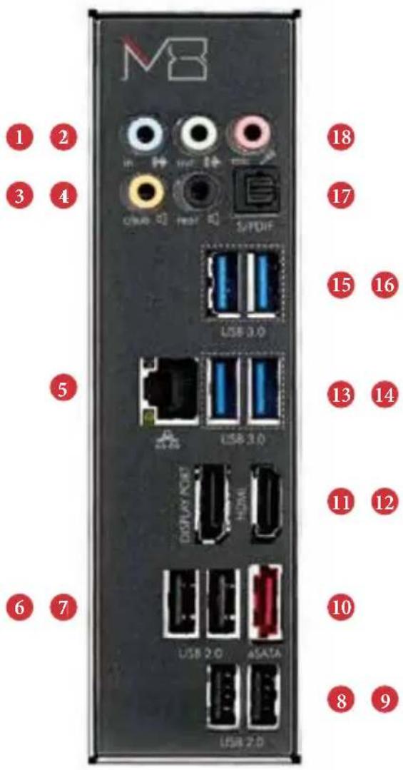
text_image
MB 1 2 3 4 USB 3.0 5 USB 3.0 DISPLAY HDMI USB 2.0 ASATA USB 2.0 18 17 15 16 13 14 11 12 10 8 9text_image
Technical diagram of an electronic device rear panel with numbered components for identificationN.º Descrição
text_image
Diagram of a black device with red connectors and labeled parts, including a MΩ button and a close-up view of its internal components.번호 설명
natural_image
Back view of a server rack with internal components and labeled ports (no readable text or symbols)번호 설명
text_image
Technical diagram of an electronic device rear panel with numbered components for identification번호 설명
text_image
Diagram of a black handheld device with labeled ports and internal components, including a close-up inset showing internal structure.番号 說明
natural_image
Back view of a computer chassis showing internal components and labeled ports (no readable text or symbols)番号 說明
text_image
Technical diagram of an electronic device rear panel with numbered components for identification番号 説明