
PHO 1 - Planer BOSCH - Free user manual and instructions
Find the device manual for free PHO 1 BOSCH in PDF.
| Brand | BOSCH |
| Model | PHO 1 |
| Product type | Electric planer |
| Rated power input | 500 W |
| Useful power output | 250 W |
| No-load speed | 19,000 rpm |
| Max. planing width | 82 mm |
| Cutting depth | 1 to 1.5 mm (adjustable in 0.25 mm increments) |
| Rebate depth | 0 to 8 mm |
| Weight (according to EPTA 01/2003) | 2.0 kg |
| Protection class | II (double insulation) |
| Rated voltage | 230/240 V |
| Sound pressure level | 83 dB(A) |
| Sound power level | 94 dB(A) |
| Vibration emission value (ah) | 5.8 m/s² |
| Blade type | Reversible carbide blade (HM/TC), 2 edges |
| Chip ejection | External extraction (Ø 35 mm) or dust bag |
| Included accessories | Parallel guide, angle guide, depth stop, hexagonal wrench, extraction adapter |
| Main functions | Planing, chamfering, rebating with guide |
| Maintenance and cleaning | Clean chip ejection regularly; replace belt if worn; use only original Bosch blades |
| Safety | Switch lock, front shoe with V-groove, motor stop before removal |
Frequently Asked Questions - PHO 1 BOSCH
User questions about PHO 1 BOSCH
0 question about this device. Answer the ones you know or ask your own.
Ask a new question about this device
Download the instructions for your Planer in PDF format for free! Find your manual PHO 1 - BOSCH and take your electronic device back in hand. On this page are published all the documents necessary for the use of your device. PHO 1 by BOSCH.
USER MANUAL PHO 1 BOSCH
Power Tools Division
70745 Leinfelden-Echterdingen
www.bosch-pt.com
1609929M00(2007.09)O/102
PHO 1

BOSCH
de Originalbetriebsanleitung
en Original instructions
fr Notice originale
es Manual original
pt Manual original
it Istruzioni originali
nI Oorspronkelijke
gebruksaanwijzing
da Original brugsanvisning
sv Bruksanvisning i original
no Original driftsinstruks
fi Alkuperäiset ojeet
el Ppwtuno 0dyw xphonc
tr Original isletme talimati

Deutsch. 6
English. Page 14
Français.. Page 21
Espanol . Pagina 29
Portugues Pagina 37
Italiano . 45
Nederland . 53
Dansk . Side 60
Svenska. Sida 67
Norsk. Side 73
Suomi . Sivu 79
Elambdaiká 86
Türkce Sayfa 94
PHO 1
Dr. Egbert Schneider Senior Vice President Engineering
Dr. Eckerhard Strötgen
Head of Product Certification

06.08.2007, Robert Bosch GmbH, Power Tools Division D-70745 Leinfelden-Echterdingen
Montage
General Power Tool SafetyWarnings
WARNING
Read all safety warnings and all instructions. Failure to follow the
warnings and instructions may result in electric shock, fire and/or serious injury.
Save all warnings and instructions for future reference.
The term "power tool" in the warnings refers to your mains-operated (corded) power tool or battery-operated (cordless) power tool.
1) Work area safety
a) Keep work area clean and well lit. Cluttered or dark areas invite accidents.
b) Do not operate power tools in explosive atmospheres, such as in the presence of flammable liquids, gases or dust. Power tools create sparks which may ignite the dust or fumes.
c) Keep children and bystanders away while operating a power tool. Distractions can cause you to lose control.
2) Electrical safety
a) Power tool plugs must match the outlet. Never modify the plug in any way. Do not use any adapter plugs with earthed (grounded) power tools. Unmodified plugs and matching outlets will reduce risk of electric shock.
b) Avoid body contact with earthed or grounded surfaces, such as pipes, radiators, ranges and refrigerators. There is an increased risk of electric shock if your body is earthed or grounded.
c) Do not expose power tools to rain or wet conditions. Water entering a power tool will increase the risk of electric shock.
d) Do not abuse the cord. Never use the cord for carrying, pulling or unplugging the power tool. Keep cord away from heat, oil, sharp edges and moving parts. Damaged or entangled cords increase the risk of electric shock.
e) When operating a power tool outdoors, use an extension cord suitable for outdoor use. Use of a cord suitable for outdoor use reduces the risk of electric shock.
f) If operating a power tool in a damp location is unavoidable, use a residual current device (RCD) protected supply. Use of an RCD reduces the risk of electric shock.
3) Personal safety
a) Stay alert, watch what you are doing and use common sense when operating a power tool. Do not use a power tool while you are tired or under the influence of drugs, alcohol or medication. A moment of inattention while operating power tools may result in serious personal injury.
b) Use personal protective equipment. Always wear eye protection. Protective equipment such as dust mask, non-skid safety shoes, hard hat, or hearing protection used for appropriate conditions will reduce personal injuries.
c) Prevent unintentional starting. Ensure the switch is in the off-position before connecting to power source and/or battery pack, picking up or carrying the tool. Carrying power tools with your finger on the switch or energising power tools that have the switch on invites accidents.
d) Remove any adjusting key or wrench before turning the power tool on. A wrench or a key left attached to a rotating part of the power tool may result in personal injury.
e) Do not overreach. Keep proper footing and balance at all times. This enables better control of the power tool in unexpected situations.
f) Dress properly. Do not wear loose clothing or jewellery. Keep your hair, clothing and gloves away from moving parts. Loose clothes, jewellery or long hair can be caught in moving parts.
English | 15
g) If devices are provided for the connection of dust extraction and collection facilities, ensure these are connected and properly used. Use of dust collection can reduce dust-related hazards.
4) Power tool use and care
a) Do not force the power tool. Use the correct power tool for your application. The correct power tool will do the job better and safer at the rate for which it was designed.
b) Do not use the power tool if the switch does not turn it on and off. Any power tool that cannot be controlled with the switch is dangerous and must be repaired.
c) Disconnect the plug from the power source and/or the battery pack from the power tool before making any adjustments, changing accessories, or storing power tools. Such preventive safety measures reduce the risk of starting the power tool accidentally.
d) Store idle power tools out of the reach of children and do not allow persons unfamiliar with the power tool or these instructions to operate the power tool. Power tools are dangerous in the hands of untrained users.
e) Maintain power tools. Check for misalignment or binding of moving parts, breakage of parts and any other condition that may affect the power tool's operation. If damaged, have the power tool repaired before use. Many accidents are caused by poorly maintained power tools.
f) Keep cutting tools sharp and clean. Properly maintained cutting tools with sharp cutting edges are less likely to bind and are easier to control.
g) Use the power tool, accessories and tool bits etc. in accordance with these instructions, taking into account the working conditions and the work to be performed. Use of the power tool for operations different from those intended could result in a hazardous situation.
5) Service
a) Have your power tool serviced by a qualified repair person using only identical replacement parts. This will ensure that the safety of the power tool is maintained.
Machine-specific SafetyWarnings
- Wait for the cutter to stop before setting the tool down. An exposed cutter may engage the surface leading to possible loss of control and serious injury.
Do not reach into the saw dust ejector with your hands. They could be injured by rotating parts.
Apply the machine to the workpiece only when switched on. Otherwise there is danger of kickback when the cutting tool jams in the workpiece. - When working, always hold the planer in such a manner that the planer base plate faces flat on the workpiece. Otherwise the planer can become wedged and lead to injuries.
- Never plane over metal objects, nails or screws. The planer blade and the blade shaft can become damaged and lead to increased vibrations.
- Secure the workpiece. A workpiece clamped with clamping devices or in a vice is held more secure than by hand.
Do not work materials containing asbestos. Asbestos is considered carcinogenic.
Take protective measures when dust can develop during working that is harmful to one's health, combustible or explosive. Example: Some dusts are regarded as carcinogenic. Wear a dust mask and work with dust/chip extraction when connectable. - Never use the machine with a damaged cable. Do not touch the damaged cable and pull the mains plug when the cable is damaged while working. Damaged cables increase the risk of an electric shock.
16 | English
Functional Description

Read all safety warnings and all instructions. Failure to follow the warnings and instructions may result in electric shock, fire and/or serious injury.
Intended Use
The machine is intended for planing of firmly supported wooden materials, such as beams and boards. It is also suitable for beveling edges and rebating.
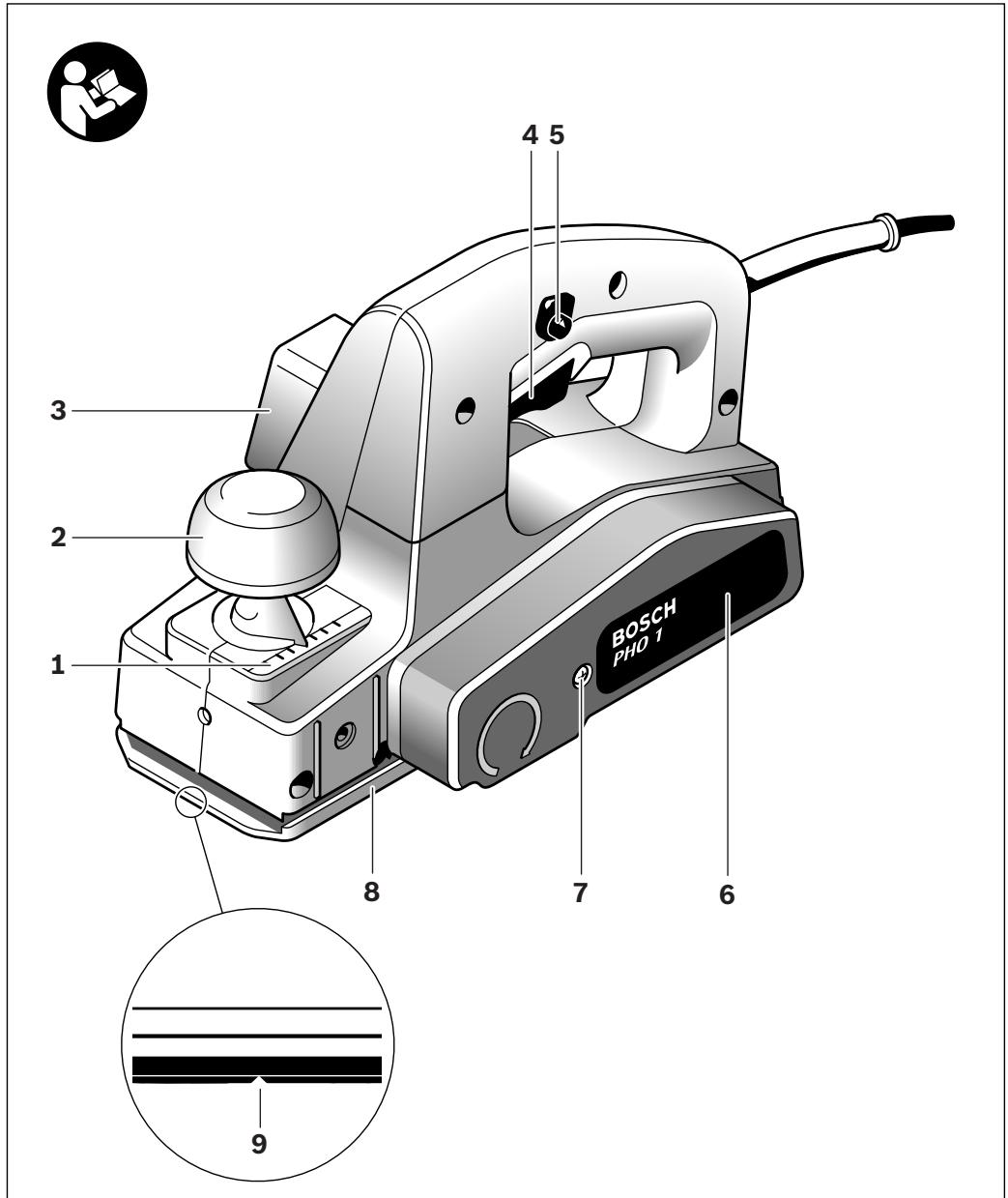
Product Features
The numbering of the product features refers to the illustration of the machine on the graphics page.
1 Planing depth scale
2 Depth adjustment knob
3 Sawdust ejector
4 On/Off switch
5 Lock-off button for On/Off switch
6 Belt cover
7 Screw for belt cover
8 Planer base plate
9 V-groove
1.0 Blade drum
11 Clamping element for blade
12 Fastening screw for planer blade
13 Carbide blade (TC)
14 Allen key
15 Extraction hose ( 35mm)^
16 Extraction adapter
17 Chip/dust bag
18 Parallel guide
19 Scale for rebating width
20 Locking nut for adjustment of rebating width
21 Fastening bolt for parallel and beveling guide
22 Angle stop
23 Locking nut for angle adjustment
24 Fastening bolt for rebating depth stop
25 Rebating depth stop
26 Drive belt
27 Large pulley
28 Small pulley
*The accessories illustrated or described are not included as standard delivery.
Noise/Vibration Information
Measured values determined according to EN 60745.
Typically the A-weighted noise levels of the product are: Sound pressure level 83 dB(A); Sound power level 94 dB(A). Uncertainty K = 3 dB.
Wear hearing protection!
Vibration total values (triax vector sum) determined according to EN 60745:
Vibration emission value a_h = 5.8m / s^2 Uncertainty K = 1.8~m / s^2
The vibration emission level given in this information sheet has been measured in accordance with a standardised test given in EN 60745 and may be used to compare one tool with another. It may be used for a preliminary assessment of exposure.
The declared vibration emission level represents the main applications of the tool. However if the tool is used for different applications, with different accessories or poorly maintained, the vibration emission may differ. This may significantly increase the exposure level over the total working period.
An estimation of the level of exposure to vibration should also take into account the times when the tool is switched off or when it is running but not actually doing the job. This may significantly reduce the exposure level over the total working period.
Identify additional safety measures to protect the operator from the effects of vibration such as: maintain the tool and the accessories, keep the hands warm, organisation of work patterns.
English | 17
Technical Data
| Planer | PHO 1 | |
| Article number | 0 603 272 2.. | |
| Rated power input | W | 500 |
| Output power | W | 250 |
| No-load speed | rpm | 19000 |
| Planing depth | mm | 1-1.5 |
| Rebating depth | mm | 0-8 |
| Planing width, max. | mm | 82 |
| Weight according to EPTA-Procedure 01/2003 | kg | 2.0 |
| Protection class | ☐/II | |
The values given are valid for nominal voltages [U] of 230/240 V. For lower voltage and models for specific countries, these values can vary.
Please observe the article number on the type plate of your machine. The trade names of the individual machines may vary.
Declaration of Conformity (C)
We declare under our sole responsibility that the product described under "Technical Data" is in conformity with the following standards or standardization documents: EN 60745 according to the provisions of the directives 2004/108/EC, 98/37/EC (until Dec. 28, 2009), 2006/42/EC (from Dec. 29, 2009 on).
Technical file at:
Robert Bosch GmbH, PT/ESC,
D-70745 Leinfelden-Echterdingen
Dr. Egbert Schneider
Dr. Eckerhard Ströttgen
Senior Vice President
Head of Product
Engineering
Certification
ppa. Maee i.v. Nogcu
05.06.2007, Robert Bosch GmbH, Power Tools Division D-70745 Leinfelden-Echterdingen
Assembly
Before any work on the machine itself, pull the mains plug.
Changing the Tool
- Be cautious when replacing the planer blades. Do not grasp the planer blades by the cutting edges. Possible danger of injury due to the sharp cutting edges of the planer blades.
Use only original Bosch carbide blades (TC).
The carbide blade (TC) has 2 cutting edges and can be reversed. When both cutting edges are dull, the planer blade 13 must be replaced. The carbide blade (TC) may not be resharpened.
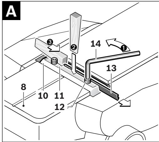
Disassembling the Planer Blade(s) (see figure A)
To reverse or replace the planer blade 13, rotate the blade drum 10 until it is parallel to the planer base plate 8.
1 Loosen the two fastening screws 12 with the Allen key 14 by approx. 1-2 turns.
If necessary, loosen the clamping element 11 by giving it a light blow with a suitable tool (e.g. a wooden wedge).
Push the planer blade 13 sideways out of the blade drum 10 with a piece of wood.
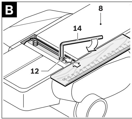
Assembling the Planer Blade(s) (see figure B)
The guide groove of the planer blade always ensures continuous height adjustment when replacing or reversing it.
If required, clean the blade seat in the clamping element 11 and the planer blade 13.
When assembling the planer blade, ensure that it is seated properly in the blade holder of the clamping element 11 and aligned flush at the side edge of the rear planer base plate 8. Afterwards tighten the 2 fastening screws 12 again with the Allen key 14.
Note: Before restarting, check if the fastening screws 12 are tightened well. Rotate the blade drum 10 by hand and ensure that the planer blade does not graze.
18 | English
Dust/Chip Extraction
Clean the chip ejector 3 regularly. Use a suitable tool (e.g., a piece of wood, compressed air, etc.) to clean a clogged chip ejector.
Do not reach into the saw dust ejector with your hands. They could be injured by rotating parts.
To ensure optimum extraction of dust/chips, always work with external dust extraction or a chip/dust bag.
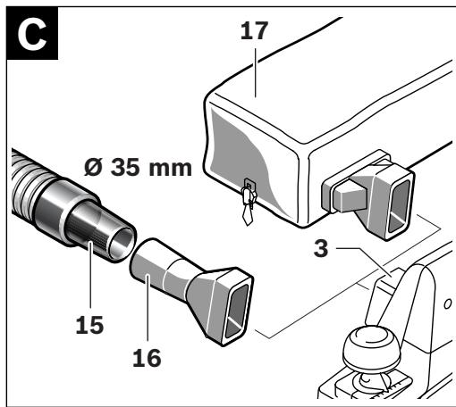
External Dust Extraction (see figure C)
Firmly attach the extraction adapter 16 to the sawdust ejector 3. An extraction hose with a diameter of 35mm can be connected to the extraction adapter 16.
Connect the vacuum hose 15 to a vacuum cleaner (accessory). An overview for connecting to various vacuum cleaners can be found at the end of this manual.
The vacuum cleaner must be suitable for the material being worked.
When vacuuming dry dust that is especially detrimental to health or carcinogenic, use a special vacuum cleaner.
Integrated Dust Extraction (see figure C)
A chip/dust bag (accessory) 17 can be used for smaller jobs. Insert the sleeve of the chip/dust bag firmly into the chip ejector 3. Empty the chip/dust bag 17 at regular intervals to maintain optimum dust collection.
Operation
Operating Modes
Adjusting the Planing Depth
With the adjustment knob 2, the planing depth can be adjusted variably from 1 - 1.5mm using the planing depth scale 1 (scale graduation = 0.25mm ).
Park Position
After the working procedure, set the depth adjustment knob 2 to position P (park position). This retracts the planer blade, allowing the power tool to be placed down without the danger of causing damage to the workpiece or the planer blade.
Starting Operation
Observe correct mains voltage! The voltage of the power source must agree with the voltage specified on the nameplate of the machine. Power tools marked with 230V can also be operated with 220V .
Switching On and Off
To start the machine, first push the lock-off button for the On/Off switch 5 and then press the On/Off switch 4 and keep it pressed.
To switch off the machine, release the On/Off switch 4.
Note: For safety reasons, the On/Off switch 4 cannot be locked; it must remain pressed during the entire operation.
Working Advice
Planing
Set the required planing depth and place the front part of the planer base plate 8 against the workpiece.
Apply the machine to the workpiece only when switched on. Otherwise there is danger of kickback when the cutting tool jams in the workpiece.
Switch the machine on and guide the machine with even feed over the surface to be planed.
To achieve high-grade surfaces, work only with low feed and apply pressure on the centre of the planer base plate.
When machining hard materials (e.g. hardwood) as well as when utilising the maximum planer width, set only low planing depths and reduce planer feed, as required.
Excessive feed reduces the surface quality and can lead to rapid clogging of the chip ejector.
English | 19
Only sharp blades achieve good cutting capacity and give the machine longer life.
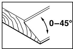
Beveling Edges (see figure G)
The V-groove 9 in the front planer base plate allows quick and easy beveling of workpiece edges. For this, place the planer with the V-groove onto the edge of the workpiece and guide it along the edge.
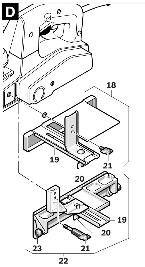
Planing with Parallel/Beveling Guide (see figures D-F)
Mount the parallel guide 18 or beveling guide 22 to the machine using the corresponding fastening bolt 21. Depending on the application, mount the rebating depth stop 25 with fastening bolt 24 to the machine.
Loosen the locking nut 20 and adjust the requested rebating width on the scale 19. Tighten the locking nut 20 again.
Adjust the requested rebating depth accordingly with the rebating depth stop 25.
Carry out the planing procedure several times until the requested rebating depth is reached. Guide the planer applying sideward supporting pressure.
Beveling with the Beveling Guide
When beveling rebates and surfaces, adjust the required slope angle with the angle adjustment 23.
Maintenance and Service
Maintenance and Cleaning
Before any work on the machine itself, pull the mains plug.
For safe and proper working, always keep the machine and ventilation slots clean.
If the machine should fail despite the care taken in manufacturing and testing procedures, repair should be carried out by an after-sales service centre for Bosch power tools.
In all correspondence and spare parts order, please always include the 10-digit article number given on the type plate of the machine.
WARNING! Important instructions for connecting a new 3-pin plug to the 2-wire cable.
The wires in the cable are coloured according to the following code:
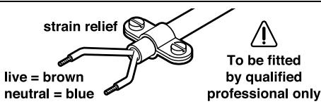
Do not connect the blue or brown wire to the earth terminal of the plug.
Important: If for any reason the moulded plug is removed from the cable of this power tool, it must be disposed of safely.
Replacing the Drive Belt (see figures H-I)
Unscrew screw 7 and take off the belt cover 6. Remove the worn drive belt 26.
Before assembling a new drive belt 26, clean both pulleys 27 and 28.
Place the new drive belt 26 on the small pulley 28 first and then work the drive belt 26 onto the large pulley 27 by hand while rotating it.
Reattach the belt cover 6 and tighten with the screw 7.
20 | English
After-sales service and customer assistance
Our after-sales service responds to your questions concerning maintenance and repair of your product as well as spare parts. Exploded views and information on spare parts can also be found under:
www.bosch-pt.com
Our customer consultants answer your questions concerning best buy, application and adjustment of products and accessories.
Great Britain
Robert Bosch Ltd. (B.S.C.)
P.O.Box 98
Broadwater Park
North Orbital Road
Denham
Uxbridge
UB95HJ
Tel. Service: +44 (0844) 736 0109
Fax: +44 (0844) 736 0146
Australia, New Zealand and Pacific Islands
Robert Bosch Australia Pty. Ltd.
Power Tools
Locked Bag 66
Clayton South VIC 3169
Customer Contact Center
Inside Australia:
Phone: +61 (01300) 307 044
Fax: +61 (01300) 307 045
Inside New Zealand:
Phone: +64 (0800) 543 353
Fax: +64 (0800) 428 570
Outside AU and NZ:
Phone: +61 (03) 9541 5555
www.bosch.com.au
Disposal
The machine, accessories and packaging should be sorted for environmental-friendly recycling.
Only for EC countries:

Do not dispose of power tools into household waste! According the European Guideline 2002/96/EC for Waste Electrical and Electronic Equipment and its implementation into national right,
power tools that are no longer usable must be collected separately and disposed of in an environmentally correct manner.
Subject to change without notice.
Français | 21
Dr. Egbert Schneider
Dr. Eckerhard Strötgen
Senior Vice President
Head of Product
Engineering
Certification
ppa. Mauu i.v. Noo
06.08.2007, Robert Bosch GmbH, Power Tools Division D-70745 Leinfelden-Echterdingen
Montage
Robert Bosch (France) S.A.S.
Dr. Egbert Schneider
Dr. Eckerhard Ströttgen
Senior Vice President
Head of Product
Engineering
Certification

06.08.2007, Robert Bosch GmbH, Power Tools Division D-70745 Leinfelden-Echterdingen
Montaje
Senior Vice President
Engineering
Dr. Eckerhard Strötgen
Head of Product
Certification

06.08.2007, Robert Bosch GmbH, Power Tools Division
D-70745 Leinfelden-Echterdingen
Montagem
- Antes de todoseworkos na ferramenta electricadeferapeuxaraficha de rede da to-mada.
Troca de ferramenta
Dr. Egbert Schneider Senior Vice President Engineering
Dr. Eckerhard Strötgen
Head of Product Certification

06.08.2007, Robert Bosch GmbH, Power Tools Division D-70745 Leinfelden-Echterdingen
Montaggio
Dr. Egbert Schneider
Dr. Eckerhard Ströttgen
Senior Vice President
Head of Product
Engineering
Certification

06.08.2007, Robert Bosch GmbH, Power Tools Division D-70745 Leinfelden-Echterdingen
Montage
Senior Vice President
Head of Product
Engineering
Certification


06.08.2007, Robert Bosch GmbH, Power Tools Division D-70745 Leinfelden-Echterdingen
Montering
Bosch Service Center
Telegrafvej 3
2750 Ballerup
Tel. Service Center: +45 (04489) 8855
Fax: +45 (04489) 87 55
E-Mail: vaerktoej@dk.bosch.com


66 | Dansk
Bortskaffelse
El-vaerktoj, tilbehor og emballage skal genbruges pa en miljovenlig maede.
Dr. Egbert Schneider
Dr. Eckerhard Strötgen
Senior Vice President
Head of Product
Engineering
Certification
ppa. Maee i.v. Nogcu
06.08.2007, Robert Bosch GmbH, Power Tools Division D-70745 Leinfelden-Echterdingen
Montage
Dra stickproppen ur nätuttaget innan arbeiten utfors pä elverktyget.
Verktygsbyte
Dr. Egbert Schneider Senior Vice President Engineering
Dr. Eckerhard Ströttgen
Head of Product Certification

06.08.2007, Robert Bosch GmbH, Power Tools Division D-70745 Leinfelden-Echterdingen
Montering
Dr. Egbert Schneider Senior Vice President Engineering
Dr. Eckerhard Ströttgen
Head of Product Certification


06.08.2007, Robert Bosch GmbH, Power Tools Division D-70745 Leinfelden-Echterdingen
Asennus
Eiokc woc to mXavma unodeiEic aopaaia
NeipieveTe va akivntonouthei o aEvac Tou maXaipiw npiv va anoTheeTo nAekptikO epyaIeio. Evac akaluntoc aEvoc maXaipiw mnopei va opnywoei otnv emipaveia kai va obnynoei otnv anwleia tou eEyxou kai oe oBapouc tpaumatouoc.
Mny bae ta xepia oac otny eEdo0 pokaviw. Mnpei va tpaumatiotei ano nepiotpepoeva eapntmuata.
Odyeite To nAektpiko epyaleio oTo uno katepyaia Teaixo mOvo otav auto biokaTeai oLeitoupyia. Diaopoptika unapxie Kivduoc va klotaae, otav to epyaleio oTo uno katepyaia Teaixio.
Otav epya2e0e va kpatate tny nlayn etai, oote to nla ma tnc nlavc va akoumpa enine6da enaw oto uno katepyaia tepaxio. Diaqopetikn na nlayn mnpei va loeueoi kai va odnynoe o traumuiouc.
Na nnu navi zete npw ano metaaikavtkeiieva, kappia nbi6ec. Mnpei va uooouv znui ta maxaipia ka o aEvocmaaipivkai va npokalov etoi auEvouc kpaaoouc.
AopaiTe To uno katepyaia Teaxio. Ea uno katepyaia Teaxio ouykpatetai aoa- latoepa me ia diatae ng ouphiicn n me ma neyn npap e to xepi oac.
Mny katepyaZeote uikn nou nepleXouv amiavto.To aivto eewpeirat oav kapkivoyo uliko.
Na laβavete npoataeutka metpa otav kata tnv epyaia oac unapxie n nepintwoan va dnmuopyntheta avuyievn, eupkntn ekpnktikn okvni. Tia napadeyiura: Meipika eisn okovnc thewpuvtai kapkivoyova. Na popate maoka npoataiac okovnc kai va xpnoiopoilete avappoqn an okovnc/pokavidiw/ ypeziw.
Mn xnpoiponoioeTo nlektpko epyaleio otav to nlektpko kaawio tou eivai xaalaevo.Mnv ayviEte To xaalaouevo kaawdo kai ByaTe To pic ano Tnv npia otav to kalwdo unootei / a a katad iapkeia tnc epyaoiac oac.Tuxov xaalaueva kaawia auavouv to kivuvo nlektpoianxiac.
Pepiypapn Aetoupyiac

Aiaabaote olec tic npoeiobonoutikec unobeiEic. Aeieic kata tnv npnTuw npoeiobonoutikwv unoBeiewu npoei va npokaleouv nkeptponla, kivduvo npkayiac /kai oBapoc traupatouc.
Xpnoo uφwva μe tov npooipuó
Dr. Egbert Schneider
Dr. Eckerhard Ströttgen
Senior Vice President
Head of Product
Engineering
Certification
ppa. Maee i.v. Nogcu
06.08.2007, Robert Bosch GmbH, Power Tools Division D-70745 Leinfelden-Echterdingen
Συναρμολόγηση
ByaTeTo 山 ano Tnv npia npiv ano oonoi- 6hnote epyaia oTo nlektipko epyaleio.
AvtikataoTaon eXapthmuatoc
Pooexe otav aalazete ta paxiaipia nadvnc. Mny niave ta paxiaipia tnc nadvnc ano tic akpec konic. Mnpoe va Tpaumataitei otic koptepec akpec konic.
Na xŋoɪpənoiεité móvo yvnoia maαaipia nλavnc HM/TC ano tyn Bosch.
To ma xai pi ano oKAnpOeTaAaIo (HM/TC) exei 2 kOweic ka i npoei va avoTpapei. O'at eivai ka o duo kowieic tou aBleiec, toTe to ma xai pi navnc 13 npenEva aAaxtheta. To ma xai pi nAynC HM/TC dev enitpeneta va troxiolei.
AnouuapmoIoynon tou maiaipiou nIavnc (Blaene eikova A)
Tia va avaotpeve t va avtikataohtnoeTe to
maxaiipi nllavnc 13 yupioTe Tnv kepaan ma xaiapiou
10 mexpi va npapaanlntei e To nelaa nllavnc 8.
XaIapawate TIC duo Biide cstepeewanC 12e To KLeidi eowteripkoEaywovou 14 yupicovtac Tc nepinou 1-2 oTPOpeC.
Av xpeiaotei,luote to stoioeio ouoepicn 11 XtuWvTac to eAoppa me eva kaTaalno epvaaleio, n.x. memu Eulivn ophiya.
Θησε με ενα κοματιξύλο το μαχαρι πλάνης 13 viα va βγει πλayiwc ἔξω από την κεφαήν μαχαρίου 10.
Euvaopoloynon tou paaxaiipou nlavnc (Bleeneikova B)
Xapn otnyauakwon obnynonc tou paiaipou nIavnc kat ayn aayn n Tnv avatpnpn Tou eEaaepalizetai navtote mua ooioppn puthetaian uwouc.
Av xpeiaotei, kathetae tn theon tou paaiou oTo oToixei ouoepic 11 kaowc kai to idio to paaiipi navnc 13.
Kata tny tono the ton tou maiaipio n lamvnc va npooexete,va kathetaai awoya otny unodoxn odynonc tou otoixeiou ouophiENC 11 kai va eUohpaumizetai me tn pueupikakun tou niaw nemuatoc nAavnc 8. sphiTe akolouwca kala tic 2 biEc otepewanC 12 me to kaeidi eowterikoou eayovou 14.
Alambdaivavkivnnc (Beneikovc H-1)
EeBldwote Tealeiwoc Tn Bida 7 kai apaipote to kaLmuMa iavTa 6. Apaipote To aapueo iavTa kivnoC 26.
Piiv tonotheetae to veo iavta kivnnc kaapioTe ka la 26 touc duo troxouc iavta 27 ka 28.
Iepaote to veo iavta kivnonc 26 npwa enaw oTo ikpo troxo iavta 28 kalakolouwC natoTeov iavta kivnonc 26, yupicovrac tov e To xepi, enawo tov meyalo troxo iavta 27.
Toonotto KaLumua iavta 6 ka ophiTe kaTa tn Biδa 7.
Tnpoue to dkaiomega aalayw.
94 | Türkiye
Dr. Egbert Schneider
Dr. Eckerhard Ströttgen
Senior Vice President
Head of Product
Engineering
Certification


06.08.2007, Robert Bosch GmbH, Power Tools Division D-70745 Leinfelden-Echterdingen
Montaj
Bosch San. ve Tic. A.S.
Ahi Evran Cad. No:1 Kat:22
Polaris Plaza
80670 Maslak/Istanbul
Müsteri Danismani: +90 (0212) 335 06 66
Müsteri Servis Hatti: +90 (0212) 335 07 52
Tasfiye


- PHO 1
- BOSCH
- Montage
- General Power Tool SafetyWarnings
- WARNING
- 1) Work area safety
- 2) Electrical safety
- 3) Personal safety
- Machine-specific SafetyWarnings
- Functional Description
- Intended Use
- Product Features
- Noise/Vibration Information
- Wear hearing protection!
- Declaration of Conformity (C)
- Assembly
- Changing the Tool
- Disassembling the Planer Blade(s) (see figure A)
- Assembling the Planer Blade(s) (see figure B)
- Dust/Chip Extraction
- External Dust Extraction (see figure C)
- Integrated Dust Extraction (see figure C)
- Operation
- Operating Modes
- Adjusting the Planing Depth
- Park Position
- Starting Operation
- Switching On and Off
- Working Advice
- Planing
- Beveling Edges (see figure G)
- Planing with Parallel/Beveling Guide (see figures D-F)
- Beveling with the Beveling Guide
- Maintenance and Service
- Maintenance and Cleaning
- WARNING! Important instructions for connecting a new 3-pin plug to the 2-wire cable.
- Replacing the Drive Belt (see figures H-I)
- After-sales service and customer assistance
- www.bosch-pt.com
- Great Britain
- Australia, New Zealand and Pacific Islands
- Disposal
- Only for EC countries:
- Montaje
- Montagem
- Troca de ferramenta
- Montaggio
- Montering
- Bortskaffelse
- Verktygsbyte
- Asennus
- Eiokc woc to mXavma unodeiEic aopaaia
- Pepiypapn Aetoupyiac
- Xpnoo uφwva μe tov npooipuó
- Συναρμολόγηση
- AvtikataoTaon eXapthmuatoc
- AnouuapmoIoynon tou maiaipiou nIavnc (Blaene eikova A)
- Euvaopoloynon tou paaxaiipou nlavnc (Bleeneikova B)
- Alambdaivavkivnnc (Beneikovc H-1)
- Montaj
- Tasfiye
Brand : BOSCH
Model : PHO 1
Category : Planer