
ZT4200E-S - Lawn mower EGO - Free user manual and instructions
Find the device manual for free ZT4200E-S EGO in PDF.


| Product Type | Zero-turn riding mower |
| Brand | EGO |
| Model | ZT4200E-S |
| Nominal voltage | 56 V |
| Cutting width (deck) | 107 cm |
| Adjustable cutting height | 25 – 100 mm (10 positions) |
| Blade rotation speed | 2400 – 3000 rpm (4 speeds) |
| Max. forward drive speed | 11.3 km/h (12.8 km/h in transport mode) |
| Max. reverse drive speed | 5.6 km/h |
| Turning radius | 0 |
| Weight (without battery) | 196 kg |
| Front / rear tire pressure (cold) | 222.1 kPa / 110.3 kPa |
| Power supply | EGO 56 V batteries (minimum capacity 15 Ah, recommended 30 Ah) |
| Charger / adapter (optional) | CHV1600E / ACA1000 |
| Operating temperature range | 0 °C – 40 °C |
| Charging temperature range | -5 °C – 40 °C |
| Guaranteed sound power level | 100 dB(A) |
| Hand / body vibrations | 1.221 m/s² / 0.568 m/s² |
| Lighting | LED headlights, side lights, rear lights, daytime running lights |
| USB port | 5 V DC, 1.5 A max |
| Drive modes | Control, Standard, Sport |
| Cruise control (CCS) | Yes |
| Safety function | Seat safety interlock, blade stop in 5 seconds |
| Maintenance | Deck wash port, blades and tires checkable |
| Spare parts | Standard blades AB4200, high-lift blade AB4201, grass collection kit ABK4200-A, etc. |
Frequently Asked Questions - ZT4200E-S EGO
User questions about ZT4200E-S EGO
0 question about this device. Answer the ones you know or ask your own.
Ask a new question about this device
Download the instructions for your Lawn mower in PDF format for free! Find your manual ZT4200E-S - EGO and take your electronic device back in hand. On this page are published all the documents necessary for the use of your device. ZT4200E-S by EGO.
USER MANUAL ZT4200E-S EGO
natural_image
Line drawing of a vehicle chassis with wheels and mechanical components (no text or symbols)
natural_image
Line drawing of a 3500 scooter seat with labeled sections B-2 and B-3, no text or symbols on the diagram itself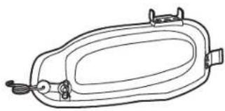
natural_image
Line drawing of a rectangular device with internal components and connectors (no text or symbols)B-4

B-5 B-6

X6X1X1
B-7 B-8 B-9 B-10


X1X2X1X1



D1
natural_image
Technical line drawing of a mechanical assembly with no visible text or symbols

The image is too blurry to recognize any text content.
natural_image
Technical line drawing of a mechanical assembly with labeled components (no readable text or symbols)




natural_image
Technical line drawing of a vehicle chassis with mechanical components, showing two views (no text or symbols)

natural_image
Technical line drawing of a vehicle engine compartment showing structural components and a downward arrow indicating motion (no text or symbols present)

natural_image
Line drawing of a small electric scooter parked next to a two-story building with a window and circular door (no text or symbols)
natural_image
Technical line drawing of a vehicle engine compartment with no visible text or symbols

E11

natural_image
Line drawing of a person riding an electric scooter (no text or symbols)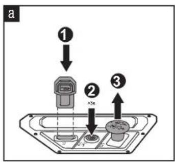

natural_image
Pure diagram of a rotating mechanical component with no text or symbolsE12

natural_image
Line drawing of a person riding an electric scooter with a hand elevated, no text or symbols present
E13

E14
natural_image
Side view of a person riding a three-wheeled electric scooter with a hand elevated, no text or symbols visible
E15

E16

E17

E18

flowchart
graph TD
    A["Top Server Rack"] --> B["Server 1"]
    A --> C["Server 2"]
    A --> D["Server 3"]
    A --> E["Server 4"]
    A --> F["Server 5"]
    B --> G["Server 6"]
    C --> H["Server 7"]
    D --> I["Server 8"]
    E --> J["Server 9"]
    F --> K["Server 10"]
flowchart
graph TD
    A["Device 1"] --> B["Device 2"]
    B --> C["Device 3"]
    C --> D["Device 4"]
    D --> E["Device 5"]
    E --> F["Device 6"]
    F --> G["Device 7"]
    G --> H["Device 8"]
E20

E21
flowchart
graph TD
    A["Top Left Motor"] -->|Upward Roll| B["Top Right Motor"]
    C["Top Right Motor"] -->|Downward Roll| D["Bottom Left Motor"]
    E["Bottom Left Motor"] -->|Upward Roll| F["Bottom Right Motor"]
    G["Bottom Right Motor"] -->|Downward Roll| H["Bottom Left Motor"]
    style A fill:#f9f,stroke:#333
    style C fill:#f9f,stroke:#333
    style E fill:#f9f,stroke:#333
    style G fill:#f9f,stroke:#333
    style B fill:#ccf,stroke:#333
    style D fill:#ccf,stroke:#333
    style F fill:#ccf,stroke:#333
    style H fill:#ccf,stroke:#333

F1

natural_image
Technical diagram of a mechanical assembly with no visible text or symbols
F2

natural_image
Line drawing of a small electric vehicle with wheels and control panel (no text or symbols)
natural_image
Illustration of a mobility vehicle with water spray and warning symbols (no text or labels)
The image is too blurry to recognize any text content.

G1
i

natural_image
Technical line drawing of a mechanical assembly with no visible text or symbols

natural_image
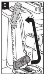
Mechanical assembly diagram showing a lever mechanism with a tool and component (no text or labels)


line
| Time Point | Value | | ---------- | ----- | | 1 | 100 | | 2 | 100 | | 3 | 100 | | 4 | 100 | | 5 | 100 | | 6 | 100 | | 7 | 100 | | 8 | 100 | | 9 | 100 | | 10 | 100 | | 11 | 100 | | 12 | 100 | | 13 | 100 | | 14 | 100 | | 15 | 100 | | 16 | 100 | | 17 | 100 | | 18 | 100 | | 19 | 100 | | 20 | 100 | | 21 | 100 | | 22 | 100 | | 23 | 100 | | 24 | 100 | | 25 | 100 | | 26 | 100 | | 27 | 100 | | 28 | 100 | | 29 | 100 | | 30 | 100 | | 31 | 100 | | 32 | 100 | | 33 | 100 | | 34 | 100 | | 35 | 100 | | 36 | 100 | | 37 | 100 | | 38 | 100 | | 39 | 100 | | 40 | 100 | | 41 | 100 | | 42 | 100 | | 43 | 100 | | 44 | 100 | | 45 | 100 | | 46 | 100 | | 47 | 100 | | 48 | 100 | | 49 | 100 | | 50 | 100 | | 51 | 100 | | 52 | 100 | | 53 | 100 | | 54 | 100 | | 55 | 100 | | 56 | 100 | | 57 | 100 | | 58 | 100 | | 59 | 100 | | 60 | 100 | | 61 | 100 | | 62 | 100 | | 63 | 100 | | 64 | 100 | | 65 | 100 | | 66 | 100 | | 67 | 100 | | 68 | 100 | | 69 | 100 | | 70 | 100 | | 71 | 100 | | 72 | 100 | | 73 | 100 | | 74 | 100 | | 75 | 100 | | 76 | 100 | | 77 | 100 | | 78 | 100 | | 79 | 100 | | 80 | 100 | | 81 | 100 | | 82 | 100 | | 83 | 100 | | 84 | 100 | | 85 | 100 | | 86 | 100 | | 87 | 100 | | 88 | 100 | | 89 | 100 | | 90 | 100 | | 91 | 100 | | 92 | 100 | | 93 | 100 | | 94 | 100 | | 95 | 100 | | 96 | 100 | | 97 | 100 | | 98 | 100 | | 99 | 100 | | Note: The data is extracted from the image file 'G7' in the provided code. The text 'Figures' are not present in the image. There is no label for the data series. The values are estimated based on the given code.


natural_image
Mechanical assembly diagram showing a component with arrows indicating motion (no text or symbols)
natural_image
Mechanical diagram showing a lever mechanism with an arrow indicating motion (no text or symbols present)G12


H1-H2<5mmH2-H1<5mm



natural_image
Illustration of a small electric mobility vehicle with raindrops and a 'X' symbol (no text or labels)
natural_image
Line drawing of a small electric scooter parked next to a modular house with a door and window (no text or symbols)
EN READ ALL INSTRUCTIONS!

READ OPERATOR'S MANUAL
SAFETY SYMBOL
The purpose of safety symbols is to attract your attention to possible dangers. The safety symbols and the explanations with them deserve your careful attention and understanding. The symbol warnings do not, by themselves, eliminate any danger. The instructions and warnings they give are no substitutes for proper accident prevention measures.
WARNING: Be sure to read and understand all safety instructions in this Operator's Manual, including all safety alert symbols such as "DANGER," "WARNING," and "CAUTION" before using this tool. Failure to follow all instructions listed below may result in electric shock, fire, and/or serious personal injury.
SYMBOL MEANING
This page depicts and describes safety symbols that may appear on this product. Read, understand, and follow all instructions on the machine before attempting to assemble and operate it.
SAFETY SYMBOLS


Do not step

This product is in accordance with applicable EC directives

Direct Current
kPa Kilopascal RPM Revolutions per minute
V Volt m Meters
in Inch cm Centimeters
Nm Newton meter mm Millimeters
°C Celsius kg Kilogram
km/h
Kilometers per hour

Waste electrical products should not be disposed of with household waste. Take to an authorized recycler.

CAUTION – Do not stare at operating lamp.

This product is in accordance with applicable UK legislation.
IPX4
Ingress Protection Degree
SAFETY SYMBOLS

The information needs to be noted
STOP
The indicated action stops
SPECIFICATIONS
| Voltage | 56 V | |
| Deck Size | 107 cm | |
| Wheel Size | Front | 279.4 x 101.6 – 127 mm |
| Rear | 457.2 x 241.3 – 203.2 mm | |
| Cold Tire Pressure | Front | 222.1 kPa |
| Rear 115.8 kPa | ||
| Turning Radius | 0 | |
| Blade Speed (RPM) | 2400; 2600; 2800; 3000 | |
| Maximum Driving Speed | Forward | 4.8 km/h, 8.1 km/h, 9.7 km/h, 11.3 km/h (12.8 km/h in Travel mode) |
| Reverse | up to 5.6 km/h | |
| Charging | Charger (Optional) | CHV1600E |
| Adaptor (Optional) | ACA1000 | |
| Charging Temperature Range | 5°C - 40°C | |
| Cutting-Height Adjustment (10 position) | 25 – 100 mm | |
| Operating Temperature 0°C- 40°C | ||
| Storage Temperature | -20°C - 70°C | |
| Weight (Without battery pack) | 196 kg | |
| Measured sound power level L_WA | 96.44 dB(A)K=0.68 dB(A) | |
| Sound pressure level at operator's ear L_PA | 84.3 dB(A)K=3.0 dB(A) | |
EN
EN
| Guaranteed sound power level L_WA (measured according to 2000/14/EC) | 100 dB(A) | |
| Vibration a_h | Hand | 1.221 m/s ^2 K=1.5 m/s ^2 |
| Body | 0.568 m/s ^2 K=1.5 m/s ^2 | |
The declared vibration total value has been measured in accordance with a standard test method and may be used for comparing one tool with another;
The declared vibration total value may also be used in a preliminary assessment of exposure.
NOTICE: The vibration emission during actual use of the power tool can differ from the declared value in which the tool is used; In order to protect the operator, user should wear gloves and ear protectors in the actual conditions of use.
RECOMMENDED ACCESSORIES
⚠ WARNING: Use only identical replacement parts listed below. Use of parts that do not meet the original equipment specifications may lead to improper performance and compromised safety.
| PART NAME MODEL | NUMBER |
| Standard Blade AB4200 | |
| High Lift Blade AB4201 | |
| Mulching Plug AMP4200 | |
| Grass Bagger Kit ABK4200-A | |
| Rear Bumper AMB1000 | |
| Cargo Box AMG1000 | |
| Sun Shade AMS1000 | |
DESCRIPTION
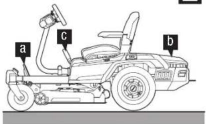
KNOW THE MOWER (Fig. A1)
- Seat
- Charging Port
- Power Unit
- LED Rear Light
-
Storage Compartment
-
LED Sidelight
- Rear Wheel (Drive Wheel)
- Wash Port
- Deck
- Deck Protector
- Anti-Scalp Wheel
- Front Wheel
- Parking-Brake Pedal
- Daytime Running Lights
- LED Headlights
- Accelerator Pedal
- Foot-Rest Area
- Side-Discharge Chute
- Deck-Height Adjustment Lever
- Seat-Suspension Adjustment Knob
- Steering Wheel
- Right Side Box
- Seat Position Adjustment Lever
- PTO Switch
- Start/Stop Button
- Safety Key
- Phone Storage Slot
- Cup Holders
- Left Paddle
- Mower Status Indicator
- LCD Screen
- Right Paddle
- Blade Speed Adjustment Button
- CCS Button
- Driving Mode Button
- LED Light Switch
- Driving Speed Adjustment Button
- Power-unit Cover Release Button
- Power-unit Cover
- Power unit with six battery compartments
- Battery-Release Button
- Hitch
- Attachment Mounting Cover
- USB Port
KNOW THE LCD SCREEN (Fig. A2)
Refer to the section "MOWER STATUS REFERENCE & FAULT CODE" for more information about the icons and indicators on the LCD screen.
- Reverse Icon
- CCS Icon
- Safety Key Icon
- LED Lights Icon
- Auto-Parking Icon
- USB Icon
- Blade Speed Indicator
- Safety Device Status Indicator
- Hour Meter
- Vacant Battery Compartment Icon
- Temperature Icon
- Occupied Battery Compartment Icon
- Driving Mode
- Fault Code Indicator
- Overload Indicator
- Low Power Indicator
- Fuel Gauge
- Load Indicator
- Driving Speed Indicator
UNPACKING
NOTICE: Save the packing materials until you have carefully inspected and satisfactorily operated the product. If any parts in packing list assembled on the machine please instantly contact EGO service.
NOTICE:: Except the tools in below packing list, all other tools mentioned in the manuals are just recommended but not provided.
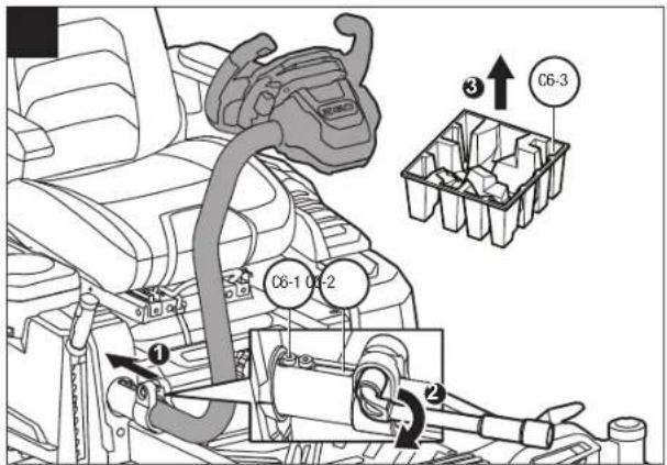
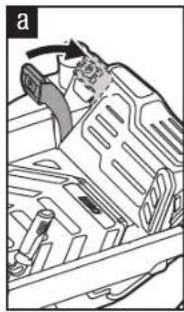
NOTICE:: Do not remove the foam block under the steering wheel before the steering wheel is properly installed. Vibration during moving may cause the damage to the steering wheel.
PACKING LIST (Fig. B)
| B-1 | Zero Turn Ride-On Mower | B-2 | Seat |
| B-3 Mulching Plug B-4 | Socket-Head Screws (2 for backup) | ||
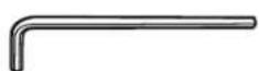
| B-5 Allen Key B-6 Socket Wrench | |||
| B-7 Open-End Wrench B-8 | Safety Keys | ||
| B-9 | Wash-Port Quick Coupler | B-10 Operator's Manual | |
EN
ASSEMBLY
INSTALLING THE SEAT (Fig. C1 - C4)
WARNING: The safety interlock system must not be disconnected or bypassed. Doing so could cause the mower to operate unexpectedly, resulting in personal injury.
NOTICE: For your safety, the mower may stop driving as the seat switch got disconnect during driving. In this case, please refer to the section "TROUBLESHOOTING" for more information.
| C1-1 | Socket C1-2 | Plug | |
| C1-3 | Cable C2-1 Seat Arm | ||
| C2-2 | Suspension Base C2-3 | Allen | Key |
| C2-4 | Socket-Head Screws | C2-5 | Seat Position Adjustment Lever |
| C3-1 | Steel Rails | C3-2 | Allen Key |
| C3-3 | Socket-Head Screws | C4-1 | Hook |
INSTALLING THE STEERING WHEEL (Fig. C5 – C6)
| C5-1 Locking Bolt | C5-2 | Bar |
| C6-1 Locating Block | C6-2 Slot | |
| C6-3 Steering Wheel Protector | ||
EN
ATTACHING THE MULCHING PLUG (Fig. C7)
| C7-1 | Side Discharge Chute | C7-2 | Mulching Plug |
| C7-3 | Movable Spring | ||
ADJUSTMENT
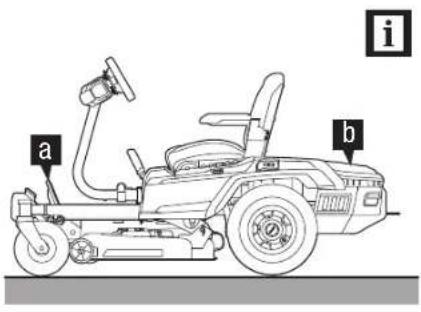
BEFORE ADJUSTMENT (Fig. D1)
ADJUSTING THE CUTTING-DECK HEIGHT (Fig. D2)
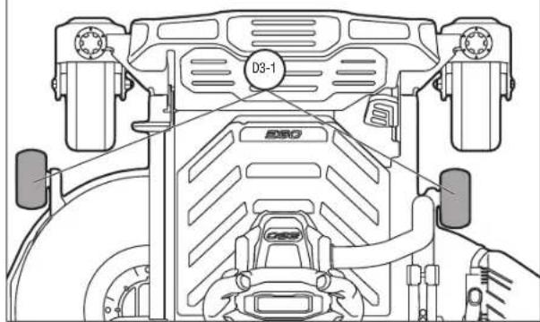
ADJUSTING THE ANTI-SCALP WHEELS (Fig. D3 - D6)
| D3-1 | Anti-Scalp Wheel D5-1 | Nut |
| D5-2 | Lug Bolt D6-1 Deck Height Label | |
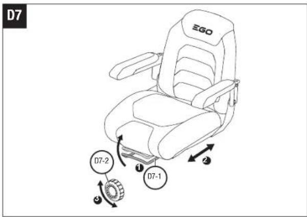
ADJUSTING THE SEAT (Fig. D7)
| D7-1 | Seat Position Adjustment Lever | D7-2 | Seat Suspension Adjustment Knob |
ADJUSTING THE STEERING WHEEL (Fig. D8)
| D8-1 | Locking Bolt D8-2 | Bar | |
| D8-3 | Locating Block D8-4 | Slot |
OPERATION
| E2-1 Released Position E2-2 | Braking Position |
NOTICE:: Never depress the parking-brake pedal to slow down the speed. Once the parking-brake pedal is depressed enough but not to the full parking position, the mower will stop moving on a flat surface, but if this happens on a slope, the mower may slide down the slope.
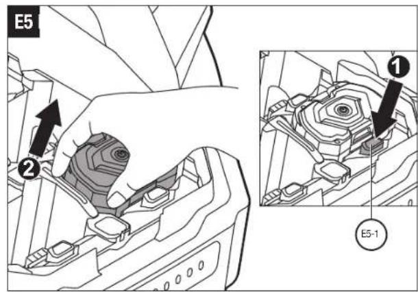
ATTACHING / DETACHING THE BATTERY PACK (Fig. E3 – E6)
In order to start this mower, EGO batteries totaling 15 Ah (2 X BA4200/BA4200T) or more are required. For best performance, we recommended use of EGO batteries
that total 30 Ah or more.
| E3-1 | Cover Release Button | E5-1 | Battery Release Button |
CHARGING THE MOWER
Use only with the recommended battery packs and chargers.
Charge the battery pack(s) separately (Fig. E7)
NOTICE: Refer to corresponding battery and charger manuals for detail instructions.
Charge the battery pack(s) via charging port (Fig. E8-E10)
| E10-1 | Dust Cap E10-2 | Charging Port |
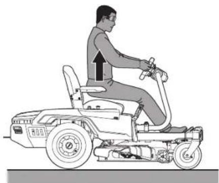
If the deck-blade system and/or the driving system fails to stop when the operator is off of the seat and if the cause cannot be determined after confirming the plug and socket connection of the seat is well connected, contact your EGO customer service center immediately.
Ensure that the work area is clear of children, bystanders, and pets.
Clear the work area of objects that may be thrown by the mower blades.
Clean debris from the mower.
Check for loose fasteners.
Check to make sure that all guards are in place and working properly.
Visually check the tires whether they are inflated.
Check the brake operation.
Adjust the deck height to the desired cutting position best suited for the lawn, and adjust anti-scalp wheels accordingly.
Adjust the seat position and make sure both pedals can be reached.
Adjust the steering wheel to desired position if necessary.
Verify the battery charge level.
Test the safety interlock system.
STARTING THE MOWER (Fig. E15 – Fig. E16)
⚠ WARNING: Avoid sudden starts, stops, and turns, as well as excessive speed, especially when first learning to operate the mower. The mower can spin rapidly, which may cause you to lose control and result in serious injury and/or damage.
⚠ WARNING: Before starting the mower, check and make sure the blades are disengaged within 5s when pushing the PTO switch downward. If the blades fail to stop, do not use the mower and contact your EGO customer service immediately.
NOTICE: Follow Fig. E17 & Fig. E18 to get the lowest driving speed and STANDARD driving mode until you are fully capable of operating the mower in all situations.
The mower will save and present the previous driving mode, driving speed and calibration of the steering wheel when restarting it.
Driving-Mode Adjustment (Fig. E17)
CONTROL: Lower acceleration, less sensitive handling, and mild turning speed to protect the grass and for new users.
6TANDARD: Perfect for everyday use.
SPORT: Higher acceleration, accurate handling, and sharp turning to maximize mowing efficiency and for mowing enthusiasts.
NOTE: The driving mode cannot be adjusted during driving. The function will activate only when the mower wheels are stopped.
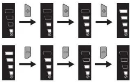
Driving Speed Adjustment (Fig. E18)
Blade Speed Adjustment (Fig. E19)
LED Lights
The headlights, sidelights and rear lights are controlled by the LED light switch.
The running lights always keep on during driving.
When backing up, if the rear lights are turned off, they will flash to warn bystanders; if the rear lights are turned on, they will remain on.
All lights will switch off automatically when the mower shuts off automatically after a period without operating.
USB Port
EN
NOTICE: The USB port provides charging power of 5 Voltage DC at up a combined draw of 1.5 Amperes and is powered only when the mower is startup
STOPPING THE MOWER (Fig. E20)
NOTICE: After more than 60 minutes without operating, the mower will automatically shut off.
Limp-Home Mode
When battery charge becomes critically low, the mower will go into Limp-Home mode to preserve enough power to travel back to the charging area.
The blades switch into low rotation speed, which could only cut very little amount of grass. Upon encountering tall and dense grass, the blades will stop rotating. The audio indicator will sound (beep) intermittently.
The mower status indicator will flash red every second, both the low-power indicator and the battery graphics on the fuel gauge will flash.
The operator should:
- Push the PTO switch downward to turn off the blade motors. The audio indicator will stop sounding when the blade motors stop.
Stop working and get to the charging area as soon as possible. The maximum distance the mower can travel is 1000m.
When the battery is nearly depleted, the icon of each occupied battery compartment and low-power indicator will blink every half a second. The mower will stop working immediately. The operator will have to transport the mower to the charging area for charging.
NOTICE: If manual pushing is needed, be sure that the batteries are disconnected from the mower and the parking-brake pedal is released from the braking position.
DRIVING THE MOWER (Fig. E21)
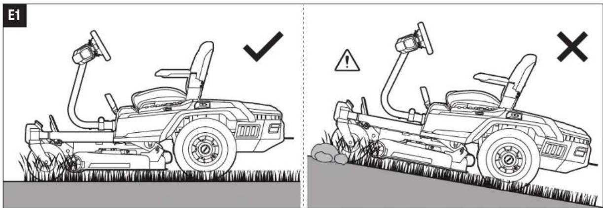
A DANGER: Stay at least two mowing widths away from any ditches, drop-offs, or water. Front wheels can rotate when the mower is stopped, even with the brake applied, and cause the mower to go over the edge or into the water and result in death or serious personal injury.
EN
⚠ WARNING: Be aware of what is behind the mower before backing up. DO NOT mow in reverse unless absolutely necessary. Always look down and behind before and while backing to make sure no children, bystanders, or pets enter the mowing area. Remember that a careless fraction of a second is sufficient to inflict death or serious injury.
⚠ WARNING: Do not operate this machine on public roadways.
⚠ WARNING: If blockage happens or you strike a foreign object, stop the motors and remove the batteries. Remove grass clippings, leaves, dirt and any other accumulated debris; thoroughly inspect the mower for damage and repair the damage before restarting and operating the mower.
USING CRUISE CONTROL (CCS)
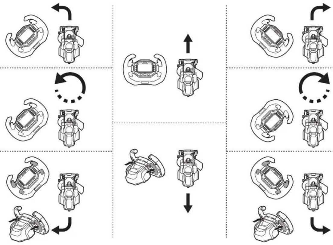
To activate CCS during driving (Fig. E22)
NOTE: The driving speed level shown on the LCD screen may not accurately represent the actual driving speed of the mower in cruise control. Press one of the speed adjustment buttons ("or") to "refresh" and adjust the driving speed level on the LCD screen.
To exit CCS and stop the mower, you may choose one of the four ways:
Slightly depress the accelerator pedal and then release it.
Pull left/right paddle(s) toward the operator and then release.
Depress the parking brake pedal. The mower will stop.
Press the CCS button.
NOTE: Depress the accelerator pedal all the way to achieve the current CCS driving speed and keep depressing. The CCS function will stop and the mower will continue driving at the current speed.
MAINTENANCE
⚠ WARNING: Always wear eye protection with side shields. Failure to do so could result in objects being thrown into your eyes resulting in possible serious injury.
⚠ WARNING: Always protect your hands by wearing heavy gloves or wrapping the cutting edges with rags or other materials when performing any maintenance on the mower blade. Always remove the safety key and battery packs when servicing or transporting the mower.
| Maintenance Service Interval | Maintenance Procedure |
| Before each use or daily | Check the safety-interlock system.Visually check the tires whether they are inflated.Inspect the blades.Inspect the entire product for damaged, missing, or loose parts such as side discharge chute, screws, nuts, bolts, caps, etc., ensuring that all guards are in place and working properly.Check and make sure the accelerator pedal could be depressed and release properly.Check the steering wheel damper. The steering wheel should be rotated with certain resistance. |
| After each use | Clean the mower deck. |
| Every 25 hours | Check the tire pressure. |
| Every 100 hours | Check the rear wheels, ensuring that the all lug nuts are fastened at the recommended torque. |
| Every 200 hours | Check the front wheels, ensuring that they turn freely. |
| Before storage | Remove the batteries from the mower.Remove the safety key from the mower.Perform all maintenance procedures listed above and thoroughly clean the mower.Inspect the entire product for damaged, missing, or loose parts, replace or tighten the corresponding ones before storage. |
| Annually | Check the parking-brake pedal.Remove the battery from the mower and set the parking-brake pedal at the braking position. Manually push the mower forwards to see whether the mower can be moved or not. If it moves, have it serviced by a qualified service technician. |
GENERAL MAINTENANCE
Cleaning the mower housing (Fig. F1 - F2)
Using wash port to clean mower deck (Fig. F3 - F4)
| F3-1 Wash Port F3-2 | Wash-Port Quick Coupler | |
| F3-3 Garden Hose | ||
NOTICE: When finishing cleaning, turn off the mower completely and then remove the garden hose and quick-coupler.
MAINTAINING THE MOWER DECK AND THE CUTTING BLADES
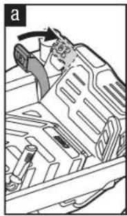
Preparation (Fig. G1)
Removing the mower deck (Fig. G2 - G3)
| G2-1 | Motor Cable G2-2 | Suspension Linkage | |
| G2-3 | Cotter Pin | ||
NOTICE: Disconnect all motor cables and cotter pins when removing the mower deck.
Replacing the cutting blades (Fig. G4 - G6)
EN
| G4-1 Stabilizer G5-1 | Bolt | |
| G5-2 Washer G5-3 Blade | ||
| G5-4 Flange G5-5 Motor Shaft |
Leveling the mower deck
a. When to level (Fig. G7 - G9)
b. Before leveling
Checking the cold tire pressure (Fig. G10)
Check the cutting blades. Remove and replace worn, cracked, and/or bent blades as necessary.
c. Preparation for leveling (Fig. G11)
d. How to leveling
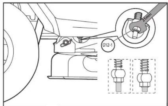
To make side-to-side adjustment (Fig. G12)
To make front-to-rear adjustment (Fig. G13)
CALIBRATING THE MOWER TRACKING SYSTEM (Fig. H1 - H2)
NOTICE: The beeping indicator will sound once both when starting calibration and when the calibration is finished.
NOTE: The calibration completed for one of the driving modes (“CONTROL”, “STANDARD”, “SPORT”) maybe not available for the other two modes. Calibrate the steering wheel in each driving mode independently as needed.
RESETTING THE MOWER TO INITIAL FACTORY SETTING (Fig. I)
NOTICE: The beeping indicator will sound once both when starting resetting and when the resetting is finished.
NOTE: When the resetting is successful, below settings will return to the initial factory setting:
driving mode
driving speed
calibration of the steering wheel
STORAGE & TRANSPORT
NOTICE: Secure the mower as needed, using straps or cables to prevent movement during transport.
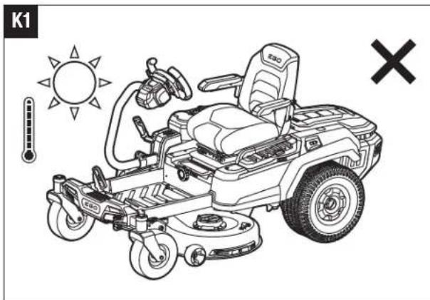
EN STORAGE (Fig. K1 - K2)
NOTICE: Remove the battery packs and store the batteries refer to the corresponding manuals.
Clean and check the mower before storage refer to the sections "CLEANING THE MOWER" and "RECOMMENDED MAINTENANCE SCHEDULE(S)".
Protecting the environment

WEEE (Waste Electrical and Electronic Equipment) Do not dispose of electrical equipment, used battery and charger into household waste! Take this product to an authorized recycler and make it available for separate collection. Electric tools must be returned to an environmentally compatible recycling facility.
TROUBLESHOOTING
EN
| PROBLEM CAUSE SOLUTION | ||
| The zero turn ride-on mower fails to drive when the accelerator pedal is depressed. | The combined Ah of the inserted batteries does not meet the requirement. | In order to start this mower, use enough EGO batteries following the instructions in section “ATTACHING/DETACHING THE BATTERY PACK” in this manual. |
| The parking brake pedal is set in the braking position. | Fully depress the parking brake pedal to release it from the braking position. | |
| The both left and right paddles are not briefly pulled toward the operator to make the mower status indicator shine green when starting the mower. | Pull BOTH left and right paddles toward the operator simultaneously and then release. The mower status indicator will shine green, which means the mower is ready to start. | |
| The operator is not sitting on the seat. | Only when the operator correctly sits on the seat, can he operate the mower. | |
| The seat switch is not connected correctly. | Remove the battery from the mower and disassemble the seat in the reverse order of the instructions in section “INSTALLING THE SEAT” in this manual to make sure that the cable plug is properly connected to the socket on the bottom of the seat. Reassemble the seat and follow the instructions in “STARTING THE MOWER” to restart the mower to see if the mower can be started. If not, contact a qualified service technician for repair. | |
| Under extreme cold weather, the driving function may not start successfully due to the low temperature protection. | Always store the mower and battery in warm environment. Restart the mower when it is warmed up. Please do not make repeated attempts under extreme cold weather which may damage the machine. | |
| The travel path of the accelerator pedal is clogged with debris. | Check and remove the debris. | |
| Failure of mechanical or electronic components of the accelerator pedal. | Contact a qualified service technician for repair. | |
EN
| PROBLEM CAUSE SOLUTION | ||
| The zero turn ride-on mower stops driving. | Left / Right paddle requires a “reset”. | Pull the left/right paddles toward the operator and release them. The mower is ready for driving when the status indicator shines green. |
| Failure of electronic components of the accelerator pedal. | Contact a qualified service technician for repair. | |
| The seat safety interlock system got disconnected during driving on a rough terrain. | Remove the battery from the mower and disassemble the seat in the reverse order of the instructions in section “INSTALLING THE SEAT” in this manual to make sure that the cable plug is properly connected to the socket on the bottom of the seat. Reassemble the seat and follow the instructions in “STARTING THE MOWER” to restart the mower to see if the mower can be started. If not, contact a qualified service technician for repair. | |
| The operator’s weight is not evenly distributed on the seat. The weight of the operator on the seat must be at least 20 kg for the seat safety interlock system to function properly | Sit on the seat properly, pull left/right or both paddles toward the operator and release them, then the mower is ready for driving. | |
| Disconnect and attach the battery pack again if necessary. | ||
| The parking-brake pedal is depressed to slow down the driving speed. Once the parking-brake pedal is depressed enough but not to the parking position, the mower will stop. | Follow the instructions in “STARTING THE MOWER” to restart the mower. | |
| The driving mode cannot be adjusted during driving. | This is a feature of the zero turn ride-on mower for safe driving. | The function will activate only when the mower wheels are stopped. |
| The zero turn ride-on mower fails to start the blades when the PTO switch is activated. | The combined Ah of the inserted batteries does not meet the requirement. | In order to start this mower, use enough EGO batteries following the instructions in section “ATTACHING/DETACHING THE BATTERY PACK” in this manual. |
| The PTO switch was not pushed down when the mower was turned off last time. | Push the PTO switch down and then up to restart the blade motors. | |
| The mower is overloaded at the moment the blades are starting to rotate, triggering the motor self-protection. | Start the mower grass cutting in lower blade speed first and do not accelerate the blade speed until the blades are rotating successfully. | |
| Under extreme cold weather, the blade motor may not start successfully due to the low temperature protection. | Always store the mower and battery in warm environment. Restart the mower when it is warmed up. Please do not make repeated attempts under extreme cold weather which may damage the machine. | |
| The blade interferes with the deformed mower deck | Call EGO Customer Service Center. | |
| The mower is driving at “TRAVEL” speed. | When the mower is driving at “TRAVEL” speed, the blade motors will automatically stop. | |
EN
EN
| PROBLEM CAUSE SOLUTION | ||
| The blades stop working during grass cutting. | The mower is overloaded. | Raise the deck cutting height or slow down the driving speed to reduce the load of the mower. |
| The mower deck is clogged with grass and debris. | Clean the mower deck and make certain that the blades have freedom of movement. | |
| The mower is overheated. | Reduce the load of the mower, by raising the deck cutting height or slowing down the blade/driving speed and allow the mower to cool. | |
| The battery pack(s) in the mower's battery compartment is overheated, resulting in combined Ah rating of all inserted batteries to not meet the requirement. | 1. The mower can continue working if the combined battery Ah rating, overheated battery excluded, meets the requirement. Once the overheated battery returns to normal temperature, it will join in powering the mower immediately. | |
| 2. If the combined battery Ah rating does not meet the requirement, the mower will not work until more battery packs are inserted into the vacant battery compartments. | ||
| 3. Reduce the load of the mower by raising the deck cutting height or slowing down the mowing when resuming operation. | ||
| The mower is in Limp-Home mode. | When the mower is in Limp - Home mode, the blades are automatically switched into low rotation speed. The operator should stop working and drive to the battery charging area as soon as possible. | |
| The mower is hit by a foreign object, resulting in motor self-protection. | Push the PTO switch down and then up to restart the blade motors. | |
| The mower speed is adjusted into “TRAVEL” mode. | When the mower speed is in “TRAVEL” mode, the blade motors will automatically stop. | |
| The audio indicator continues sounding. | The mower is in Limp-home mode and the blades are not turned off. | Push the PTO switch down to turn off the blade motors. The audio indicator will stop sounding when the blade motors are turned off. |
| The mower stops driving on a slope and the operator is off the seat without setting the parking-brake pedal at the braking position. | Set the parking-brake pedal in the braking position before leaving the mower on the slope. | |
| The battery indicators are still on when the mower is turned off. | When the mower is turned off on ground without removing the battery pack(s) from the mower, the battery indicators, start/stop button and CCS button will remain illuminated for a period. | No action is needed. The battery indicators will go off when the mower shuts off after a period. Refer to the section “STOPPING THE MOWER” for specific time. |
| When the mower is turned off on a slope without setting the parking-brake at the braking position, the battery indicators will keep on until the battery charge is depleted. The audio indicator keeps sounding at the same time. | Set the parking-brake pedal in the braking position before leaving the mower on the slope. | |
| The LCD screen fails to be illuminated with all icons on. | Start/stop button has been pressed for sufficient time. | The LCD screen will only display the “fuel gauge” when the start/stop button is pressed briefly. |
| The LCD screen will turn on after the start/stop button has been pressed for sufficient time. | ||
| The mower cuts unevenly, with significant height difference front to rear. | The blades are dull. | Charpen or replace the cutting blade as instructed in this manual. |
| The blades are bent. | Replace the bent cutting blade following the instructions in section “REPLACING THE CUTTING BLADES”. | |
| The mower deck is not leveled, resulting in different cutting blade height. | Level the mower deck following the instructions in section “LEVELING THE MOWER DECK”. | |
| The actual grass cutting height is not aligned with the claimed height. | The mower deck nuts are loosened on the suspension linkage | Follow the instructions in section “LEVELING THE MOWER DECK” to make correct front-to-rear adjustment for the mower deck and securely tighten the nuts on the suspension linkage. |
| The mower deck is damaged or seriously worn. | Follow the instructions in section “REMOVING THE MOWER DECK” to have mower deck replacement. | |
| The mower does not mulch properly. | Wet grass clippings are sticking to the underside of the deck. | Wait until the grass dries before mowing. |
| The mower is set to cut too much grass at once. | Raise the deck cutting height. | |
EN
EN
| PROBLEM CAUSE SOLUTION | ||
| Excessive vibration. | The cutting blades are loose. | Tighten the blade bolt to the recommended torque. |
| The blades are bent. | Replace the bent cutting blade following the instructions in section “REPLACING THE CUTTING BLADES”. | |
| The mower deck is not leveled. | Level the mower deck following the instructions in section “LEVELING THE MOWER DECK”. | |
| The mower deck nuts are loosened on the suspension linkage. | Tighten the nuts on the suspension linkage. | |
| The mower is set to cut too much grass at one. | Raise the deck cutting height. | |
| There are grass or debris remaining on the ground after mowing. | The mower is set to cut too much grass at once when the grass is tall. | Begin with a high cutting height and reduce it until the desired mowing result is attained. Grass over 152 mm tall should be mowed twice, at successively lower cutting heights. |
| The grass is wet. | Do not mow when the grass is wet until the grass dries. | |
| The driving speed is high. | Slow down the driving speed. | |
| The blade speed is low. | Increase the blade speed gradually. | |
| Short run time of the mower with included battery. | Lawn terrain, grass conditions, cutting-height setting, driving speed, blade speed, etc. will greatly affect the running time. | Raise the deck cutting height and slow down the blade speed to reduce the cutting load. |
| The mower is not tracking straight. | The tire pressures for the left and right rear wheels are different. | Check and adjust the air pressure in both rear wheel tires, according to the section “SPECIFICATIONS”. |
| The driving speed for the left and right rear wheels are different. | Calibrate the steering wheel following the instructions in section “CALIBRATING THE MOWER TRACKING SYSTEM”. | |
| The parking-brake pedal cannot not be released from the braking position or is slow to spring back. | There may be debris or dirt getting inside the parking-brake pedal. | Open the parking-brake pedal box to thoroughly clean the box inside and close it. Reset the parking-brake pedal to see whether the problem is solved. If not, contact a qualified service technician for repair. |
| The mower cannot be charged via charging port with the mower status indicator shining solid red. | The plug of the charger is not correctly inserted into the charging port on the mower. | Reconnect the charger plug to see whether the mower can be charged normally. |
| There is no power in the wall outlets. | No action is needed. Wait until the power recovers. | |
| Charger malfunction. | Call EGO Customer Service Center for inspection and have charger repaired if needed. | |
| The charger port on the mower is defective. | Call EGO Customer Service Center. | |
| The charging time via the mower charging port is too long. | Using EGO Adapter ACA1000 for charging requires long time. | Use EGO charger CHV1600E for charging the zero turn ride-on mower directly. |
| The battery cannot be fully charged via the mower charging port. | Firmware bug of the mower or the battery or the charger failure. | Reset the charger by unplugging the charger and waiting for longer than several minutes. Then reconnect the plug to the power supply. If this does not solve the problem, call EGO Customer Service Center. |
| The mower cannot be started after cleaning. | Improper cleaning, such as water getting on the electric components, LCD screen etc. | Follow the instructions in section “GENERAL MAINTENANCE” to clean the mower correctly. |
| the mower caught in rain accidentally, leave it in the air to dry or use compressed air to dry it. | ||
| The mower deck gets clogged fast. | The mower deck was not properly cleaned after previous use. | Clean the mower deck after each use, following the section “USING WASH PORT TO CLEAN MOWER DECK”. |
| The mower easily loses traction when climbing up on the slope. | The tires of the rear wheels are worn. | Seek local service to replace the wheel tires. |
| Mowing on a steep slope. | The mower should not be used to mow slopes steeper than at required degree. | |
| When the mower is stopped on a slope with the parking-brake pedal pressed, the mower can roll down the slope. | The brake components are excessively worn due to improper operation of the mower. | Call EGO Customer Service Center for repair. |
| There is no water coming from the wash port when attempting to wash the deck. | The wash-port quick coupler is not properly mounted onto the wash port. | Re-attach the wash-port quick coupler until you hear a clear click after firmly pushing. If it does not work, call EGO Customer Service Center. |
| An abnormal sound is heard when manually pushing the mower without starting it. | The sound comes from the magnets inside the driving motor. | it is normal and no action is needed. |
| The steering wheel cannot be rotated. | The steering wheel assembly is clogged with debris. | Check and remove the debris. |
| The mower does not turn left/right when the steering wheel is rotated. | Failure of electronic or mechanical components. | Call EGO Customer Service Center for repair. |
| The mower fails to stop when releasing the accelerator pedal. | The return path of the accelerator pedal is clogged with debris. | Check and remove the debris. |
| The CCS button is pressed unintentionally while driving. The mower is in cruise-control mode | Check if the CCS icon is illuminated on the LCD screen, and exit the CCS as necessary. Refer to chapter “USING CRUISE CONTROL (CCS)” | |
EN
EN
| PROBLEM CAUSE SOLUTION | ||
| The CCS function cannot be activated or turned off. | The CCS button is not pressed properly. | Press the CCS button until the CCS icon is illuminated on the LCD screen, or disappears from the LCD screen. |
| The mower fails to drive reverse when left/right paddle(s) is pulled toward the operator. | The mower status indicator does not show green and the mower is not ready for driving. | Follow the section “STARTING THE MOWER” to make the mower status indicator show green and mower is ready for driving. |
| The left/right paddle(s) is not pull toward the operator properly. | Pull left paddle or right paddle or both paddles simultaneously toward the operator until a “click” sound is heard. | |
| The left/right paddle(s) is not kept pulled toward the operator. | To drive in reverse, at least one of the paddles has to be kept pulled toward the operator. | |
| The left/right paddle(s) is broken. | Contact a qualified service technician for repair. | |
MOWER STATUS REFERENCE & FAULT CODE
EN
| LCD Display | Description | Fault Code on LCD | Mower Status Indicator | Beeper Cause Solution | |
| ≡D | LED lights Icon shows on the LCD screen. | n/a OFF | No | The headlights, sidelights, and rear lights are turned on by the LED light switch. | |
| USB Icon shows on the LCD screen. | n/a OFF | No | USB icon illuminates that a USB device can work after the mower is started correctly. | ||
| Fuel Gauge Icon shows on the LCD screen. | n/a OFF | No | It indicates the average charge capacity of inserted batteries | ||
| 8888H | Hour Meter Icon shows on the LCD screen. | n/a OFF | No | It shows the total driving time of mower, in hours and cannot be reset. | |
| Load indicator Icon shows in the ECO range. | n/a OFF | No | It indicates the current load of the mower. | ||
| Reverse Icon shows on the LCD screen. | n/a OFF | No | It indicates the mower is driving backward. | ||
| Safety key icon blinks. n/a OFF No | The safety key is not inserted. | ||||
| Key Control Panel Box Assembly is broken. |
EN
| LCD Display | Description | Fault Code on LCD | Mower Status Indicator | Beeper Cause Solution | |
| 1 23 45 6 | The icon of a certain battery compartment blinks. | n/a OFF | No | A certain battery during discharging is over-current. | |
| 1 23 45 6 | The icon of the empty battery compartment blinks | n/a OFF | No | Battery capacity is not sufficient to allow the mower to work. | |
| OVERLOAD | The overload indicator blinks | n/a | Flashes red | One beep | The blade motor is overloaded. |
| The side discharge chute is clogged with grass and debris. | |||||
| There is an interference between the blade and the mower deck. | |||||
| # | The temperature icon blinks. | n/a OFF | One beep | The mower is overheated. | |
| The mower is too cold. | |||||
| 12345678 | The temperature icon and the exact occupied battery compartment blink at the same time. | n/a OFF | No | The battery pack in the corresponding. Numbered battery compartment is overheated. | |
EN
EN
| LCD Display | Description | Fault Code on LCD | Mower Status Indicator | Beeper Cause Solution | |
| The icons of each occupied battery compartment, low power indicator, and fuel gauge blink every 1 second at the same time on the LCD screen. The first LED fuel-gauge & mower status indicator blinks too. | n/a | Flashes red | Keeps beeping until the PTO switch is pushed downward. | The battery packs are low on charge and the mower is in Limp Home mode. | |
| The icon of each occupied battery compartment and low power indicator blink every half a second, the first LED fuel-gauge will flash red every half a second too. | n/a | Flashes red | Keeps beeping | The battery parks are nearly depleted. | |
| The auto-parking icon blinks on the LCD. | n/a OFF | Keeps beeping | The mower is parked on a slope and the operator leaves the mower without setting the parking-brake pedal at the braking position. | ||
| Brake pedal icon shows on the LCD | n/a OFF | No | The parking brake pedal is set at the braking position. |
NOTE: If a fault code appears on LCD screen, remove all battery packs and re-insert them a few minutes later. If this doesn't solve the problem, follow the fault code troubleshooting below.
EN
| LCD Display | Description | Fault Code on LCD | Mower Status Indicator | Beeper Cause Solution | |
 | Seat sensor icon shows on the LCD | n/a OFF | No | If with the operator is seated on the seat and the icon is on, stop operating the mower immediately and check the seat connection. If the seat connection with the mower is confirmed correct, please contact a qualified service technician for repairs. | |
 | PTO Switch icon blinks n/a | OFF No | Before restarting the mower, push the PTO switch down to turn off the blade motors. Please see “TROUBLESHOOTING” section in this manual for reference. | ||
 | Energy regeneration icon blinks occasionally. | n/a OFF | No | This is normal operation. No action is needed. | |
 | CCS icon blinks n/a OFF No | The CCS (cruise control system) function has failed. The CCS function could not be set when the mower is driving at very low speed or is driving in reverse. |
EN
| LCD Display | Description | Fault Code on LCD | Mower Status Indicator | Beeper Cause Solution | ||
| See “Fault Code” | Left driving motor falls in rotation. | PCBA controlled left driving motor fails. | 413 OFF | One beep | PCBA failure | |
| Plug (Triple-phase, power wire) connecting the left driving motor with the corresponding PCBA is loosened. | 317 OFF | One beep | Loose connection | |||
| Plug (Six pins, signal wire) connecting the left driving motor with the corresponding PCBA is loosened. | 301 OFF | One beep | Loose connection | |||
| Left driving motor fails. | 317 OFF | One beep | Motor failure | |||
| See “Fault Code” | Right driving motor fails in rotation | PCBA controlled right driving motor fails. | 313 OFF | One beep | PCBA failure | |
| Plug (Triple-phase, power wire) connecting the right driving motor with the corresponding PCBA is loosened. | 417 OFF | One beep | Loose connection | |||
| Plug (Six pins, signal wire) connecting the right driving motor with the corresponding PCBA is loosened. | 401 OFF | One beep | Loose connection | |||
| Right driving motor fails. | 417 OFF | One beep | Motor failure | |||
| See “Fault Code” | Left blade motor fails in rotation | PCBA controlled left blade motor fails | 607 n/a | One beep | PCBA failure | |
| Plug (Triple-phase, power wire) connecting the left blade motor with the corresponding PCBA is loosened. | 509 n/a | One beep | Loose connection | |||
| Left blade motor fails | 509 n/a | One beep | Motor failure | |||
| See “Fault Code” | Right blade motor fails in rotation | PCBA controlled right blade motor fails | 507 n/a | One beep | PCBA failure | |
| Plug (Triple-phase, power wire) connecting the right blade motor with the corresponding PCBA is loosened. | 609 n/a | One beep | Loose connection | |||
| Right blade motor fails | 609 n/a | One beep | Motor failure | |||
| See “Fault Code” | Accelerator pedal fails | 311/411 | OFF One beep | PCBA failure | ||
| 307/407 | Loose connection | |||||
| See “Fault Code” | Steering wheel fails | 312/412 | OFF One beep | PCBA failure | ||
| Loose connection | ||||||
| See “Fault Code” | Parking brake fails, the mower cannot be driven. | Parking brake PCBA, which is in the front frame assembly, is broken. | 309/409 | OFF One beep PCBA failure | ||
| Parking brake switch and/or wire is broken. | 801 OFF | One beep | Wire/Switch failure | |||
EN
EN
| LCD Display | Description | Fault Code on LCD | Mower Status Indicator | Beeper Cause Solution | |
| OFF Charging Prot Fault | n/a Solid | RED n/a | The charging port is in open circuit. | ||
| n/a Solid | RED n/a | There is no power supply. | |||
| n/a Solid | RED n/a | The fuse is blown. | Have repairs performed by a qualified service technician. | ||
| See “Fault Code” | Charging Port Fault 204 n/a | One beep | The charging port is in open circuit. | ||
| See “Fault Code” | Battery Box Assembly not functioning. | 217 n/a | One beep | The power source from Battery Box assembly is broken. The LED headlights and USB will not work. | |
| 310/410 | OFF One beep | The connection between Type C wires of Battery Box assembly and other Type C wires of the mower is out of work. | |||
| 201/202/203 | OFF One beep | The BMS of the Battery Box assembly is broken. | |||
| See “Fault Code” | Start/Stop Switch Fault | 314/414 | OFF One beep | Switch PCBA failure or bad wire connection for Start/stop Switch. | |
| See “Fault Code” | LCD Screen Fault | 315/415 | OFF One beep | LCD assembly is broken or bad wire connection of the LCD assembly. | |
WARRANTY
EN
EGO WARRANTY POLICY
Please visit the website egopowerplus.com for full terms and conditions of the EGO Warranty policy.
LISTA DE PEÇAS (IMAGEM B)
in Pollice cm Centimetro
Nm Newton metro mm Millimetro
°C Grado Celsius kg Chilogrammo
in Inch cm Centimeter
Nm Newtonmeter mm Millimeter
°C Celsius
km/u
Kilometer per uur

OPSLAG (afb. K1 - K2)
in Tum cm Centimeter
Nm Newtonmeter mm Millimeter
°C Celsius
km/h
Kilometer per timme

FÖRVARING OCH TRANSPORT
TRANSPORTERA GRÄSKLIPPAREN
(bild J1 - J5)
GENERELT VEDLIKEHOLD
VEDLIKEHOLD AV KLIPPERDEKKET OG KLIPPEBLADEN
FORBEREDELSE (fig. G1)
POLITYKA GWARANCYJNA EGO
palce Palec cm Centimetry
Nm Newtonmetr mm Milimetry
°C Celsius kg
Kilogram
km/h
Kilometry za hodinu
BEZPEČNOSTNÍ SYMBOLY

INSTALACE SEDADLA (obr. C1 - C4)
A CSOMAG TARTALMA (B ÁBRA)
CITIȚI MANUALUL DE INSTRUCTIUNI
SIMBOLUL DE SECURITATE
in Inch cm Centimetri
Nm Newton metru mm Milimetri
°C Celsius kg Kilograme
in Palec cm centimetri
nm Newton meter mm milimetri
°C Celzij kg
Kilogram
km/h
Kilometri na uro
VARNOSTNI SIMBOLI

in Coliai cm Centimetrai
Nm Niutonmetrai mm Milimetrai
°C Celsijaus laipsniai kg Kilogramai
km/h Kilometrai per valanda
SAUGOS SIMBOLIAI

LUGEGE KASUTUSJUHENDIT
OHUTUSSÜMBOL
g_3g_5b_0b_0m_1g_2s-d_ms_6b_0q_0g_0 b_1g_2g_0d_0g_0s g_1g_3g_0d_0d_1f_6g_0m b_3g_5b_0m_1g_2d_1.

zsmbgomgdgmo bdoLboddmszmoL qmbg. g3gmzs3doMol mgggmszogdol dglsdsodolsq.

| E10-1 | ∂θ396ωσ∂θ390 E10-2 | φσθβ630δ3m6ηο |
EGO- 1 30006000s 3m45679980s 856y0000985s.
UPOZORENJE – DRŽITE ŠAKE I STOPALA DALJE

Garantovani nivo zvučne snage. Prema Direktivi Evropske zajednice.


Ne gaziti

م chloride; Ec. Ec. Ec. Ec. Ec. Ec. Ec. Ec. Ec. Ec. Ec. Ec. Ec. Ec. Ec. Ec. Ec. Ec. Ec. Ec. Ec. Ec. Ec. Ec. Ec. Ec. Ec. Ec. Ec. Ec. Ec. Ec. Ec. Ec. Ec. Ec. Ec. Ec. Ec. Ec. Ec. Ec. Ec. Ec. Ec. Ec. Ec. Ec. Ec. Ec. Ec 100
تلف.
הכלה,הכלההוּרָהוּרָהוּרָהוּרָהוּרָהוּרָהוּרָהוּרָהוּרָהוּרָהוּרָהוּרָהוּרָהוּרָהוּרָה
.הכלההוּרָהוּרָהוּרָהוּרָהוּרָהוּרָהוּרָהוּרָהוּרָהוּרָהוּרָהוּרָהוּרָהוּרָהוּרָה
הכלה 14
תְרָה בַלְאָה .15
הכלה.16
לְרָה אַעֹת הִי. 17
natural_image
Line drawing of a self-driving electric vehicle (no text or symbols present)ZT4200E-S



- EN READ ALL INSTRUCTIONS!
- READ OPERATOR'S MANUAL
- SAFETY SYMBOL
- SYMBOL MEANING
- SAFETY SYMBOLS
- SPECIFICATIONS
- RECOMMENDED ACCESSORIES
- DESCRIPTION
- KNOW THE MOWER (Fig. A1)
- KNOW THE LCD SCREEN (Fig. A2)
- UNPACKING
- ASSEMBLY
- INSTALLING THE SEAT (Fig. C1 - C4)
- EN
- ATTACHING THE MULCHING PLUG (Fig. C7)
- ADJUSTMENT
- OPERATION
- CHARGING THE MOWER
- STARTING THE MOWER (Fig. E15 – Fig. E16)
- Driving-Mode Adjustment (Fig. E17)
- Driving Speed Adjustment (Fig. E18)
- Blade Speed Adjustment (Fig. E19)
- LED Lights
- USB Port
- STOPPING THE MOWER (Fig. E20)
- Limp-Home Mode
- DRIVING THE MOWER (Fig. E21)
- USING CRUISE CONTROL (CCS)
- To activate CCS during driving (Fig. E22)
- MAINTENANCE
- GENERAL MAINTENANCE
- MAINTAINING THE MOWER DECK AND THE CUTTING BLADES
- Leveling the mower deck
- CALIBRATING THE MOWER TRACKING SYSTEM (Fig. H1 - H2)
- RESETTING THE MOWER TO INITIAL FACTORY SETTING (Fig. I)
- STORAGE & TRANSPORT
- EN STORAGE (Fig. K1 - K2)
- Protecting the environment
- TROUBLESHOOTING
- MOWER STATUS REFERENCE & FAULT CODE
- WARRANTY
- EGO WARRANTY POLICY
- OPSLAG (afb. K1 - K2)
- FÖRVARING OCH TRANSPORT
- TRANSPORTERA GRÄSKLIPPAREN
- GENERELT VEDLIKEHOLD
- VEDLIKEHOLD AV KLIPPERDEKKET OG KLIPPEBLADEN
- POLITYKA GWARANCYJNA EGO
- BEZPEČNOSTNÍ SYMBOLY
- SIMBOLUL DE SECURITATE
- VARNOSTNI SIMBOLI
- SAUGOS SIMBOLIAI
- LUGEGE KASUTUSJUHENDIT
- OHUTUSSÜMBOL
- ZT4200E-S
Brand : EGO
Model : ZT4200E-S
Category : Lawn mower