
TY-WK5P1SW - TV Accessories PANASONIC - Free user manual and instructions
Find the device manual for free TY-WK5P1SW PANASONIC in PDF.


| Product Type | Wall mounting bracket for plasma TV |
| Brand | Panasonic |
| Model | TY-WK5P1SW |
| Compatibility | Panasonic 46, 50 and 54 inch plasma TVs |
| Mounting Type | Vertical, wall mount |
| Bracket Weight | Approximately 2.3 kg |
| Main Material | Steel |
| Color | Black (estimate) |
| Included Parts | Top and bottom base brackets, left and right base brackets, M5x10 screws (4), M8x24 hex socket countersunk head screws (4), toothed lock washers (4), insulating washers (4), positioning stickers (2), long unit tightening bolt (1), M6x50 unit tightening screw (1), hex key (1) |
| Required Tools | Hex key provided, Phillips head screwdriver (not provided) |
| Required Clearance Around TV | 10 cm above, 10 cm left, 15 cm right, 10 cm below |
| Installation | By a professional, at least two people |
| Maintenance | Clean with a soft dry cloth; use diluted neutral detergent if necessary. Do not use benzene, thinner, or wax. |
| Safety | Do not use with TVs other than those listed; do not mount on a non-vertical surface; do not block ventilation openings. |
| Repairability | Replaceable mounting parts (standard commercially available screws) |
| Warranty | According to Panasonic conditions (not specified in the manual) |
Frequently Asked Questions - TY-WK5P1SW PANASONIC
User questions about TY-WK5P1SW PANASONIC
0 question about this device. Answer the ones you know or ask your own.
Ask a new question about this device
Download the instructions for your TV Accessories in PDF format for free! Find your manual TY-WK5P1SW - PANASONIC and take your electronic device back in hand. On this page are published all the documents necessary for the use of your device. TY-WK5P1SW by PANASONIC.
USER MANUAL TY-WK5P1SW PANASONIC
Fitting Instructions
Plasma TV wall-hanging bracket (Vertical mounting type)
Before commencing work, carefully read these instructions and the manual for the plasma TV to ensure that fitting is performed correctly.
(Please save these instructions. You may need them when maintaining or moving the bracket.)
Ensure that the installation location is strong enough to support long-term use. - If its strength becomes insufficient over the course of long-term use, the plasma TV may drop, possibly causing injury. Fitting work and connection equipment expansion should never be done by any other than a qualified installation specialist. - Incorrect fitting may cause equipment to fall, resulting in injury. Include a safety factor when considering the strength of the proposed fitting location. - If strength is not sufficient the equipment may fall, resulting in injury. Do not fit at a location that cannot bear the load. - If the fitting location lacks sufficient strength the equipment may fall. Do not disassemble or modify the wall-hanging bracket. - Otherwise the unit may be dropped and become damaged, and personal injury may result.
CAUTION
Do not use any television and displays other than those given in the catalogue. - Otherwise the unit may be dropped and become damaged, and personal injury may result. Do not fit at any locations subject to humidity, dust, smoke, steam or heat. - This may have an adverse effect on the plasma TV and cause fire or electric shock. The work of fitting or removing the plasma TV must be performed by at least two people. - The plasma TV may fall and cause injury. Do not fit facing upwards, sideways or upside down. - This may cause heat to build up inside the plasma TV unit, resulting in a fire. Leave clearances all around the plasma TV of at least 10 cm (3.9 inches) above, at least 10 cm (3.9 inches) on the left, at least 15 cm (5.9 inches) on the right and at least 10 cm (3.9 inches) below. Ensure that the space between the back of the plasma TV and the wall behind is not blocked. - The plasma TV unit has air blow holes on the top, and air suction holes on the bottom and rear. Covering these may result in a fire. Install the plasma TV by taking only the steps which are specified in these instructions: Do not install it in any other way. - Otherwise the unit may be dropped and become damaged, and personal injury may result. Install the mounting screws and power cable in such a way that they will not make contact with the inside parts of the wall. - Electric shocks may result from contact with any metal objects inside the wall. For installation, use the special-purpose constituent parts. - Otherwise, the plasma TV may fall off the wall, possibly causing injury. Remove the product that will not be used any longer. - Otherwise the product may fall down and personal injury may result.
Requests regarding handling
1) Exercise care when selecting the location for the TV because it may discolor or deform due to light or heat if it is placed where it is exposed to direct sunlight, or near a heater. 2) Clean the wall-hanging bracket by wiping it with a soft, dry cloth (such as cotton or flannel). If the bracket is very dirty, remove the dirt using a neutral detergent diluted in water, and then wipe it clean with a dry cloth.
Do not use benzene, thinner, or furniture wax as this may cause the coating to peel.
(For information on cleaning the display unit, see the display unit's instruction manual. If using a chemically-treated cloth, follow the instructions supplied with the cloth.)
3) Do not affix adhesive tape or stickers to the product. Doing so may dirty the surface of the wall-hanging bracket. Do not allow long-term contact with rubber, vinyl products or the like. (Doing so will cause deterioration.) 4) Take care during installation as shocks can cause 'panel cracks' to the plasma TV unit.
Caution:
This bracket is intended for only Panasonic plasma TV models (See back cover). Use with other apparatus is capable of resulting in instability causing possible injury.
PROFESSIONAL INSTALLATION IS REQUIRED. PANASONIC DISCLAIMS ANY PROPERTY DAMAGE AND/OR SERIOUS INJURY, INCLUDING DEATH RESULTING FROM IMPROPER INSTALLATION OR INCORRECT HANDLING.
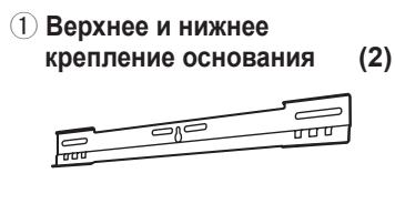
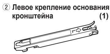
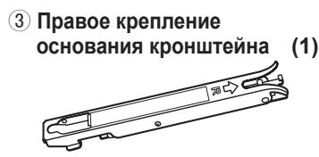
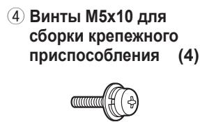
TY-WK5P1SW Wall-hanging bracket (Vertical mounting type) Parts used to assemble the wall-hanging bracket
| ① Base upper and lower fittings (2) | ② Bracket base left fitting (1) | ③ Bracket base right fitting (1) | ④ M5x10 screws for assembling the fixture (4) |
Parts used for installation
View of fully assembled fixture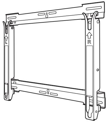
| A M8×24 Allen head countersunk screws (4) | D Positioning stickers (2) |
| B Dished toothed washers (4) | E Long bolt for securing the unit (1) |
| C Insulation spacers (4) | F Screw M6 x 50 for securing the unit (1) |
| G Allen wrench (included tool) (1) |
Please note the following before proceeding with installation:
The plasma TV unit which will be attached to the wall-hanging bracket consists of the display unit, tuner unit and speakers.
Precautions for wall-hanging bracket fitting
The wall-hanging bracket is for use in attaching a plasma TV unit to a vertical wall for viewing. Do not fit to any surface other than a vertical wall. To ensure correct plasma TV performance and prevent trouble, do not fit at any of the following locations.
- Near sprinklers or fire/smoke detectors
- Where there is a risk of exposure to vibration or impact
- Near high-voltage wires or dynamic power supplies
- Near sources of magnetism, heat, water vapor or soot
- Locations exposed to air blown from heating equipment
- Where droplets of condensation from an air conditioner or other unit may form.
Fit using techniques suited to the structure and materials of the fitting location. Use commercially available screws with a nominal diameter of 6 mm (0.2 inches) that are suited to the wall material (wood, steel frame, concrete etc.) you are fitting the bracket to. For the TV power supply plug, use a power supply outlet that can be reached easily. Ensure good air flow so that the equipment ambient temperature does not exceed 40°C (104 F). Failure to do this may cause heat to build up inside the plasma TV, resulting in malfunction. Spread a soft blanket or cloth over the floor so that the plasma TV and floor will not be marked or scratched during the assembly and installation work. When screwing down the parts, ensure that the screws are neither insufficiently tightened nor over tightened. Take sufficient care to ensure safety around you when performing the assembly and installation work or while moving about during the course of the work. Do not install the Plasma TV underneath ceiling lamps (spotlights, halogen lamps, etc.). Otherwise, the cabinet may be bent or damaged by high heat.
1. Assembling the wall-hanging bracket
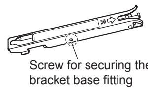
- Remove the screws for securing the bracket base left ② and right ③ fittings.
- Lay the base upper and lower fittings ① and the bracket base left and right fittings ② and ③ as shown in the figure.
- Fit the tabs of the bracket base left and right fittings into the cutouts of the base upper and lower fittings above, and secure them using the two screws ④ used to assemble the bracket.
(Tightening torque: 1.2 to 1.5 N·m)
- Open slightly the bottom of the bracket base left and right fittings, and fit their tabs into the cutouts of the base upper and lower fittings, and secure them using the two screws ④ used to assemble the bracket.
(Tightening torque: 1.2 to 1.5 N·m)
- Tighten the screws for securing the bracket base left ② and right ③ fittings which were loosen in step 1.
Note
- Please hold the bracket base left and right fittings as you work with the assembled wall hanging bracket. Holding the base upper and lower fittings might deform this unit.
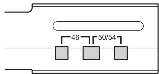
Base upper and lower fittings ①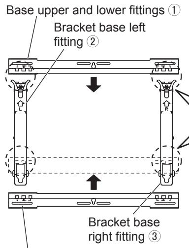
Inside : 46-inch model
Outside : 50 or 54-inch model
M5x10 screws for assembling the fixture ④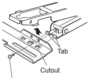
2. Checking the strength of the installation location
- The wall-hanging bracket weighs approximately 2.3 kg (5.1 lbs).
Refer to the instruction manual of the plasma TV, and check the weight of the plasma TV unit which will be fitted into the wall-hanging bracket.
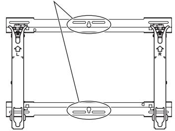
- Refer to the outline drawing of the wall-hanging bracket shown on the right, and check the wall strength at the six installation positions shown. If the strength at any of these positions is lacking, provide sufficient reinforcement.
Notes
- There are five pre-drilled mounting holes at the top and another five at the bottom of the wall-hanging bracket. Use the spare holes provided if wood or some other material is used for the wall and a sufficient level of mounting strength cannot be ensured by anchoring the fixture at the six positions shown on the right. However, bear in mind that, depending on which materials the mounting surface is made of, cracks may form on the surface if the screws are used at positions which are too close together.
- Mount or place only a plasma TV on the fixture: Do not mount or place any other product.
- For details on the dimensions applying when the plasma TV is mounted, refer to the outline drawing (See back cover).
Unit: mm (inches) Use the screws without fail to anchor the fixture.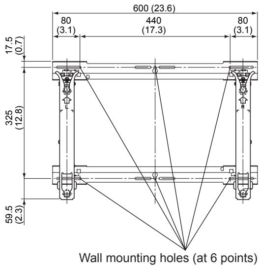
3. Installing the wall-hanging bracket on the wall
Notes
- If it is necessary to embed bolts or nuts in the wall prior to installing the wall-hanging bracket because the wall is made of concrete, for instance, locate the positions of the holes by putting the actual wall-hanging bracket in place on the wall or by calculating the hole positions from the outline drawing, and then embed bolts and nuts with a nominal diameter of 6 mm (0.2 inches) or their equivalent. When embedding the bolts, ensure that their heads protrude by 10 to 15 mm (0.4 to 0.6 inches) from the surface of the wall. In the case of the 46-inch model, limit the extent to which the screws and bolts used in the center holes of the base upper and lower fittings (3 holes on each fitting) protrude from the wall to within 5 mm (0.2 inches).
- For installing the wall-hanging bracket onto the wall, use screws with a nominal diameter of 6 mm (0.2 inches) or their equivalent available from a hardware store and suited to the materials of the installation area on the wall.
- Anchor the screws in at least six locations.
- Install the wall-hanging bracket so that the arrows indicated on it are pointing upward.
- First of all, secure the screw in the upper center hole A.
- Use a level to ensure that the fixture is not tilting on one side, and then secure the screws in the five remaining holes.
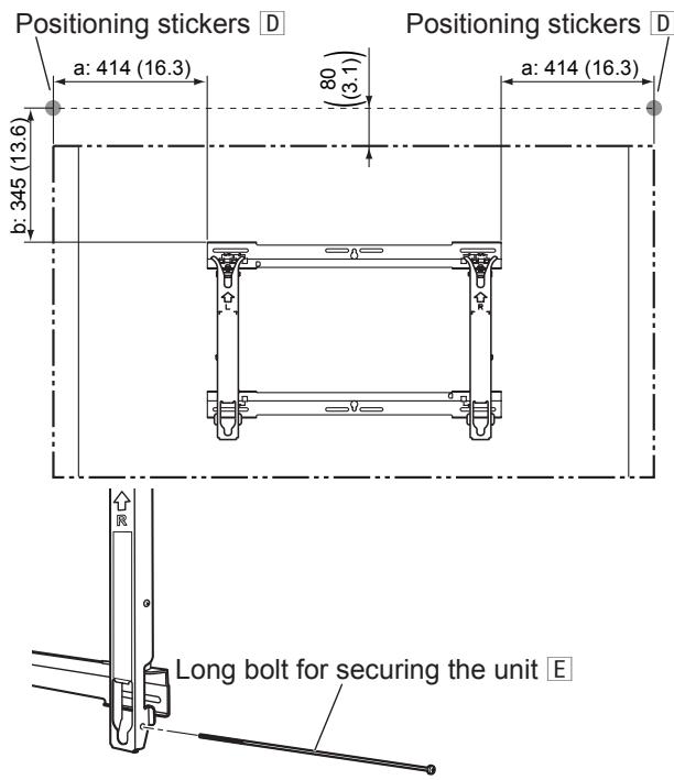
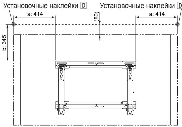
- To provide a guideline for attaching the plasma TV unit, adhere the two positioning stickers D to the wall in the same places as shown in the figure on the right. For the adhesion positions (one at the left and one at the right), refer to the outline drawings (See back cover).
- The positioning seals are adhered at positions which are 80 mm (3.1 inches) above the plasma TV unit.
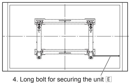
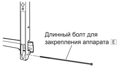
- Loosely secure the long bolt for securing the unit E (by rotating the bolt through 2 or 3 turns) into the screw hole located underneath the right side of the bracket base right ③ fitting.
Note
- When only the display unit of the 46-inch model is to be used, the long bolt for securing the unit E will be visible from the right side. If the installation conditions or other factors are such that this bolt is unsightly, use the screw for securing the unit E instead to secure the unit loosely. In this case, use a long Phillips head screwdriver (at least 40 cm (15.7 inches) long).
In the case of the 46-inch model, limit the extent to which the screws and bolts protrude to within 5 mm (0.2 inches).
Unit: mm (inches) (Example showing where the stickers are adhered on the 54-inch model)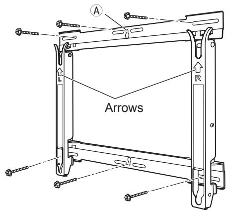
4. Attaching the insulation spacers to the display unit
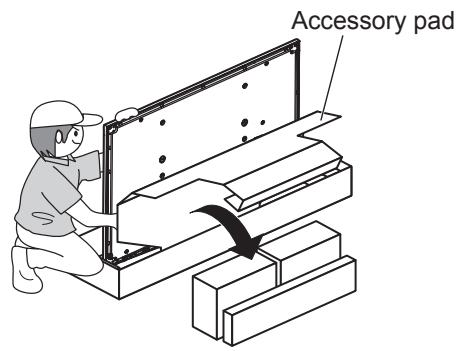
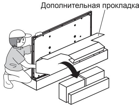
- Remove the top part of the outer cardboard box used for the plasma TV unit, and pull the protective bag down. To ensure that the plasma TV unit does not fall over, provide support at the front.
- Open the accessory pad. Remove the installation stand, accessory box and speaker box from the outer cardboard box.
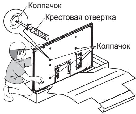
- Remove the four caps from the display unit using a Phillips head screwdriver.
Note
- Keep the installation stand and also the caps which were removed in a safe place.
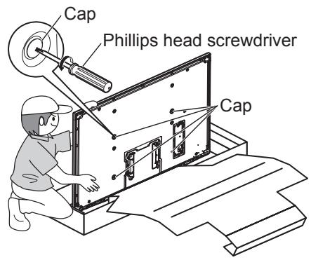
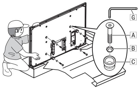
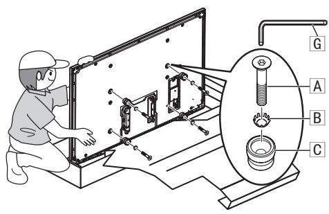
- Using the supplied Allen wrench G, mount the 4 Allen head countersunk screws A, 4 dished toothed washers B and 4 insulation spacers C provided at the locations where the caps were attached, as shown in the figure on the right. (Tightening torque: 3 to 4 N·m)
- If the insulation spacers C are not attached during the assembly process, the display unit may be damaged as a result.
- Connect the HDMI cable (either the one provided or one obtained separately) to the display unit. Use the HDMI cable in the length which is appropriate for the distance from where the tuner unit is to be installed.
Notes
- For details on how to attach the speakers and other parts packed with the plasma TV unit and to connect the HDMI cable, refer to the operating instructions of the plasma TV unit.
- When a full Hi-Vision wireless unit is to be used, follow the instructions given in the unit's operating instructions.
5. Attaching and securing the display unit to the wall-hanging bracket
- Using the positioning stickers adhered to the wall as guidelines, align the top of the display unit at the left and right.
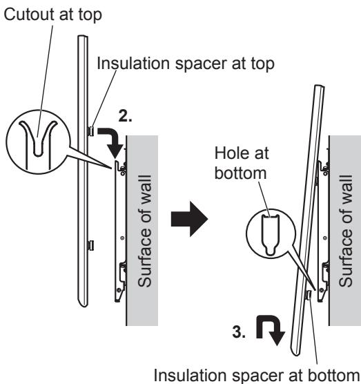
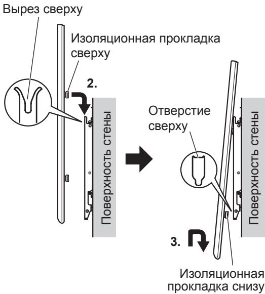
- Engage the insulation spacers at the top of the display unit with the cutouts at the top of the bracket unit, and slowly lower them into place.
- While lifting the display unit slightly, insert the bottom insulation spacers into the holes at the lower end of the wall-hanging bracket, and then pull the display unit straight down into place.
CAUTION
- If the plasma TV is lifted too much, its top part will become disengaged from the wall-hanging bracket.
- Tighten up the long bolt for securing the unit E, which was secured loosely in step 5 of section 3, until it will go no further.
Note
- Tightening up the long bolt for securing the unit E or the screw for securing the unit F too much may cause the bracket to be bent out of shape.
- Lift the display unit slightly, and check that it is firmly secured in place.
- Connect the HDMI cable to the tuner unit.
How to remove the plasma TV from the wall-hanging bracket
Note
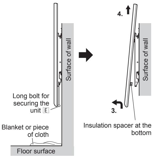
- Place a soft blanket or piece of cloth underneath the plasma TV unit. Remove the long bolt for securing the unit E or the screw for securing the unit F which is attached to the side of the wall-hanging bracket.
- Otherwise, the long bolt for securing the unit E or the screw for securing the unit F may drop down by mistake, leaving marks on the surface of the floor.
- Disconnect the wires connecting the plasma TV to the other units.
- While lifting the bottom part of the plasma TV, pull the plasma TV toward you.
- Once the insulation spacers at the bottom have been released, lift the plasma TV straight up.
- Ensure that the plasma TV unit, which has now been removed from the wall-hanging bracket, is kept upright while it is being handled so that no load will be applied to its front or back panel.
Warning
Do not install the unit in places exposed to moisture, dust, soot, or heat.
- This may have a negative effect on the plasma TV and lead to fire or electric shock.
Installation and removal of the plasma TV should be performed by at least two people.
Use with other apparatus may lead to instability, which could result in injury.
PROFESSIONAL INSTALLATION IS REQUIRED. PANASONIC COMPANY IS NOT RESPONSIBLE FOR ANY DAMAGE AND/OR SERIOUS INJURY, INCLUDING DEATH, RESULTING FROM INCORRECT INSTALLATION OR INCORRECT HANDLING.
Wall-hanging bracket TY-WK5P1SW (for vertical mounting) Parts used for assembling the wall-hanging bracket
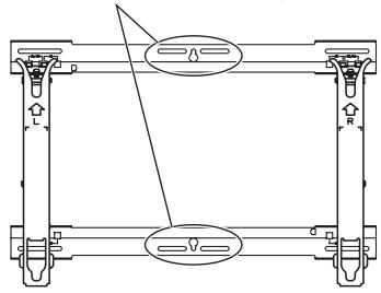
Holes for wall mounting (in the grooves)
Be sure to use the screws for securing the mounting bracket.
3. Wall-mounting the bracket for wall mounting
Notes
- If it is necessary to embed screws or hooks into the wall for mounting the bracket for wall mounting, for example, if the wall is made of concrete, mark the locations of the holes, place the actual wall-mounting bracket in the mounting position on the wall, or calculate the locations for the holes according to the dimensional drawing, and then embed screws or hooks with a nominal diameter of 6 cm or equivalent. When embedding the bolts, check that their heads protrude from the wall surface by 10-15 mm.
In the case of models with a 46-inch screen, limit the distance that the screws or bolts, used in the central holes of the upper and lower mountings of the base (3 holes for each mounting), protrude from the wall to 5 mm.
- For wall-mounting the bracket for wall mounting, use screws with a nominal diameter of 6 mm or equivalent, purchasing them from a hardware store, and suitable for the wall material in the mounting area. - Attach the screws in at least six places.
- Install the bracket for wall mounting so that the arrows marked on it point upward. 2. First, attach a screw in the central upper hole A.
- Use a level to ensure that the mounting bracket is not tilted to either side, and then attach screws in the remaining holes.
4. To mark the orientation for mounting the TV, attach two mounting stickers to the wall in the same places as shown in the figure on the right. For details on the sticker locations (one on the left and one on the right), refer to the dimensional drawings (see the back cover). - The mounting stickers are attached at locations 80 mm above the TV dimensions.
- Loosely fasten the long bolt for attaching the device E (by turning the bolt 2 or 3 turns) into the hole or screw hole located on the right side of the right mounting base of the bracket ③.
Note
Only in the case of using models with a 46-inch screen, the long bolt for attaching device E will be visible from the right side. If the installation conditions or other factors cause the bolt to look unattractive, use the screw for attaching device F instead, to loosely fasten the device. In this case, use a long Phillips screwdriver (at least 40 cm long).
In the case of models with a 46-inch screen, limit the distance that the screws and bolts protrude to 5 mm.
Units: mm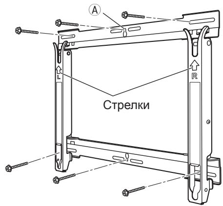
(Example showing the sticker attachment locations for models with a 54-inch screen)
- Keep the mounting stand and the removed caps in a safe place.
- Using the supplied Allen wrench G, mount the 4 Allen head countersunk screws A, 4 dished toothed washers B and 4 insulation spacers C provided at the locations where the caps were attached, as shown in the figure on the right. (Tightening torque: 3 to 4 N·m)
- If the insulation spacers C are not attached during the assembly process, the display unit may be damaged as a result.
- Connect the HDMI cable (either the one provided or one obtained separately) to the display unit. Use the HDMI cable in the length which is appropriate for the distance from where the tuner unit is to be installed.
Notes
- For details on how to attach the speakers and other parts packed with the plasma TV unit and to connect the HDMI cable, refer to the operating instructions of the plasma TV unit.
- When a full Hi-Vision wireless unit is to be used, follow the instructions given in the unit's operating instructions.
5. Attaching and fixing the display to the wall-mounting bracket
1. Using the wall-mounting brackets attached to the wall as guides, align the top part of the display left and right. 2. Insert the insulation spacers into the cutouts on the top part of the display and the top part of the bracket, then gently lower them into place. 3. Slightly lift the display, insert the lower insulation spacers into the holes on the lower parts of the wall-mounting bracket, and then lower the display straight into place.
CAUTION
- If the plasma TV is tilted too strongly, its top part may protrude from the wall-mounting bracket.
- Tighten the long screws for attaching the unit E, which should be loosely fastened to allow the actions of step 5 in section 3, until they are fully tightened.
Incorrect and strong tightening of the wall bracket for the apparatus E or the screw for the apparatus F can lead to deformation of the bracket. 5. Slightly lift the bracket and check that it is securely fixed in place. 6. Connect the HDMI cable to the tuner.
4. Pull the bracket away from the wall to secure the apparatus E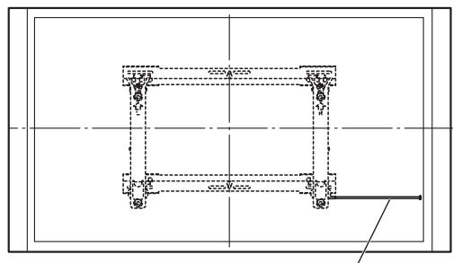
Fully assembled structure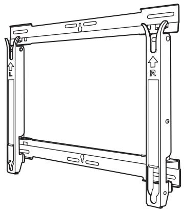
3. Attach the wall bracket to the wall
Attachment
-If necessary, install the screws or nuts before mounting the wall bracket, because the wall is made of concrete, mark the wall by holding the bracket against it or taking into account the distance between the holes with the help of a level, and after that install the screws and nuts with a nominal diameter of 6 mm or equivalent. When installing the screws, make sure they protrude from the surface by 10 to 15 mm. ※For 46-inch models, do not let the screws protrude from the wall more than 5 mm beyond the screws used in the central holes of the upper and lower brackets (with holes in each bracket). -For mounting the wall bracket, use screws with a nominal diameter of 6 mm or equivalent, which are available in hardware stores and are suitable for the wall material in the mounting area. Tighten the screws with a wrench in six places. 1. Install the wall bracket so that the arrows on it point upward. 2. First tighten the screw in the upper central hole A. 3. Using a level, adjust the horizontal position of the structure, then tighten the screws in the five holes that remain.
- FITTING INSTRUCTIONS
- CAUTION
- REQUESTS REGARDING HANDLING
- TY-WK5P1SW WALL-HANGING BRACKET (VERTICAL MOUNTING TYPE) PARTS USED TO ASSEMBLE THE WALL-HANGING BRACKET
- PARTS USED FOR INSTALLATION
- PLEASE NOTE THE FOLLOWING BEFORE PROCEEDING WITH INSTALLATION
- PRECAUTIONS FOR WALL-HANGING BRACKET FITTING
- ASSEMBLING THE WALL-HANGING BRACKET
- NOTE
- CHECKING THE STRENGTH OF THE INSTALLATION LOCATION
- NOTES
- INSTALLING THE WALL-HANGING BRACKET ON THE WALL
- ATTACHING THE INSULATION SPACERS TO THE DISPLAY UNIT
- ATTACHING AND SECURING THE DISPLAY UNIT TO THE WALL-HANGING BRACKET
- HOW TO REMOVE THE PLASMA TV FROM THE WALL-HANGING BRACKET
- WARNING
- WALL-MOUNTING THE BRACKET FOR WALL MOUNTING
- ATTACHING AND FIXING THE DISPLAY TO THE WALL-MOUNTING BRACKET
- ATTACH THE WALL BRACKET TO THE WALL
- ATTACHMENT
Brand : PANASONIC
Model : TY-WK5P1SW
Category : TV Accessories