
TY-WK4P1RW - TV Accessories PANASONIC - Free user manual and instructions
Find the device manual for free TY-WK4P1RW PANASONIC in PDF.

User questions about TY-WK4P1RW PANASONIC
0 question about this device. Answer the ones you know or ask your own.
Ask a new question about this device
Download the instructions for your TV Accessories in PDF format for free! Find your manual TY-WK4P1RW - PANASONIC and take your electronic device back in hand. On this page are published all the documents necessary for the use of your device. TY-WK4P1RW by PANASONIC.
USER MANUAL TY-WK4P1RW PANASONIC
natural_image
Technical line drawing of a mechanical frame assembly (no text or symbols)Model No.
TY-WK4P1RW
Fitting Instructions
Plasma TV wall-hanging bracket (Adjustable angle type)
Before commencing work, carefully read these Instructions and the Manual for the plasma TV to ensure that fitting is performed correctly.
(Please save these instructions. You may need them when maintaining or moving the bracket.)
Ensure that the installation location is strong enough to support long-term use.
- If its strength becomes insufficient over the course of long-term use, the plasma TV may drop, possibly causing injury.
Fitting work and connection equipment expansion should never be done by any other than a qualified installation specialist.
- Incorrect fitting may cause equipment to fall, resulting in injury.
Include a safety factor when considering the strength of the proposed fitting location.
- If strength is not sufficient the equipment may fall, resulting in injury.
Do not fit at a location that cannot bear the load.
- If the fitting location lacks sufficient strength the equipment may fall.
Do not disassemble or modify the wall-hanging bracket.
- Otherwise the unit may be dropped and become damaged, and personal injury may result.
CAUTION
Do not use any television and displays other than those given in the catalogue.
- Otherwise the unit may be dropped and become damaged, and personal injury may result.
Do not fit at any locations subject to humidity, dust, smoke, steam or heat.
- This may have an adverse effect on the plasma TV and cause fire or electric shock.
The work of fitting or removing the plasma TV must be performed by at least two people.
- The plasma TV may fall and cause injury.
Do not fit facing upwards, sideways or upside down.
- This may cause heat to build up inside the plasma TV unit, resulting in a fire.
Provide spacing around the plasma TV of at least 10 cm to the top, the side and the bottom, leave a clearance between the rear panel and the wall.
- The plasma TV unit has air blow holes on the top, and air suction holes on the bottom and rear. Covering these may result in a fire.
Install the plasma TV by taking only the steps which are specified in these instructions: Do not install it in any other way.
- Otherwise the unit may be dropped and become damaged, and personal injury may result.
Install the mounting screws and power cable in such a way that they will not make contact with the inside parts of the wall.
• Electric shocks may result from contact with any metal objects inside the wall.
For installation, use the special-purpose constituent parts.
- Otherwise, the plasma TV may fall off the wall, possibly causing injury.
Remove the product that will not be used any longer.
- Otherwise the product may fall down and personal injury may result.
Requests regarding handling
1) Exercise care when selecting the location for the TV because it may discolor or deform due to light or heat if it is placed where it is exposed to direct sunlight, or near a heater.
2) Clean the wall-hanging bracket by wiping it with a soft, dry cloth (such as cotton or flannel). If the bracket is very dirty, remove the dirt using a neutral detergent diluted in water, and then wipe it clean with a dry cloth. Do not use benzene, thinner, or furniture wax as this may cause the coating to peel.
(For information on cleaning the display unit, see the display unit's instruction manual. If using a chemically-treated cloth, follow the instructions supplied with the cloth.)
3) Do not affix adhesive tape or stickers to the product. Doing so may dirty the surface of the wall-hanging bracket. Do not allow long-term contact with rubber, vinyl products or the like. (Doing so will cause deterioration.)
4) Take care during installation as shocks can cause ‘panel cracks’ to the plasma TV unit.
Caution:
This bracket is intended for only Panasonic plasma TV models (See page 80-83). Use with other apparatus is capable of resulting in instability causing possible injury.
PROFESSIONAL INSTALLATION IS REQUIRED. PANASONIC DISCLAIMS ANY PROPERTY DAMAGE AND/OR SERIOUS INJURY, INCLUDING DEATH RESULTING FROM IMPROPER INSTALLATION OR INCORRECT HANDLING.
TY-WK4P1RW Wall-hanging bracket (Adjustable angle type)
Parts used to assemble the wall-hanging bracket
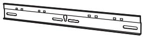
① Base upper and lower fittings (2)
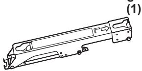
② Bracket base left fitting
natural_image
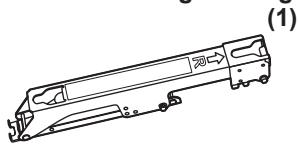
Line drawing of a vehicle chassis frame (no text or symbols)③ Bracket base right fitting
natural_image
Technical line drawing of a mechanical component with no visible text or symbols④ M5x8 screws for assembling the fixture (4)

Parts used for installation
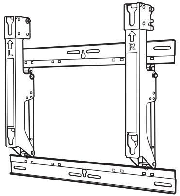
View of fully assembled fixtur
natural_image
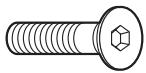
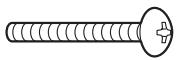
Technical line drawing of a mechanical frame assembly with no visible text or symbolsA M8×32 Allen head countersunk screws (4)
(4)
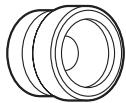
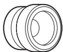
D Spacers (4)

B Dished toothed washers (4)

(4)
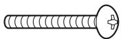
E M5x50 Unit fastening screws (2)
C Insulation spacers (4)
(4)
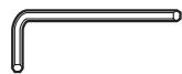
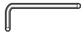
F Allen wrench (included tool) (1)
Precautions for wall-hanging bracket fitting
◆ Installation and removal work must be carried out only by a qualified technician.
If the unit is installed or removed improperly, the display may fall down and personal injury may result.
The wall-hanging bracket is for use in attaching a plasma TV unit to a vertical wall for viewing. Do not fit to any surface other than a vertical wall.
◆ To ensure correct plasma TV performance and prevent trouble, do not fit at any of the following locations.
- Near sprinklers or fire/smoke detectors
- Where there is a risk of exposure to vibration or impact
- Near high-voltage wires or dynamic power supplies
- Near sources of magnetism, heat, water vapor or soot
- Locations exposed to air blown from heating equipment
- Where droplets of condensation from an air conditioner or other unit may form.
◆ Fit using techniques suited to the structure and materials of the fitting location.
Use commercially available screws with a nominal diameter of 6 mm (0.2 inches) that are suited to the wall material (wood, steel frame, concrete etc.) you are fitting the bracket to.
◆ For the TV power supply plug, use a power supply outlet that can be reached easily.
◆ Ensure good air flow so that the equipment ambient temperature does not exceed 40 °C (104 °F). Failure to do this may cause heat to build up inside the plasma TV, resulting in malfunction.
◆ Spread a soft blanket or cloth over the floor so that the plasma TV and floor will not be marked or scratched during the assembly and installation work.
When screwing down the parts, ensure that the screws are neither insufficiently tightened nor over tightened.
Take sufficient care to ensure safety around you when performing the assembly and installation work or while moving about during the course of the work.
Do not install the Plasma TV underneath ceiling lamps (spotlights, halogen lamps, etc.). Otherwise, the cabinet may be bent or damaged by high heat.
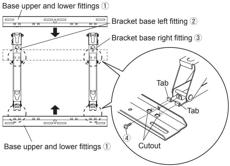
1. Assembling the wall-hanging bracket
Lay the base upper and lower fittings ① and the bracket base left and right fittings ② and ③ as shown in the figure.
Fit the protrusions (tabs) of the bracket base left and right fittings into the cutouts (2 on the left and 2 on the right) in the base upper and lower fittings, and secure the parts using the four screws ④ for assembling the fixture.
(Tightening torque: 1.2 to 1.5 N·m)
2. Checking the strength of the installation location
① The wall-hanging bracket weighs approximately 3.2 kg (7.1 lbs).
Refer to the instruction manual of the plasma TV, and check the weight of the plasma TV unit which will be fitted into the wall-hanging bracket.
② Refer to the outline drawing of the wall-hanging bracket shown on the right, and check the wall strength at the six installation positions shown. If the strength at any of these positions is lacking, provide sufficient reinforcement.
Notes
- There are five pre-drilled mounting holes at the top and another five at the bottom of the wall-hanging bracket.
Use the spare holes provided if wood or some other material is used for the wall and a sufficient level of mounting strength cannot be ensured by anchoring the fixture at the six positions shown on the right.
However, bear in mind that, depending on which materials the mounting surface is made of, cracks may form on the surface if the screws are used at positions which are too close together. - Mount or place only a plasma TV on the fixture: Do not mount or place any other product.
- For details on the dimensions applying when the plasma TV is mounted, refer to the outline drawing (on page 80-83).
Unit: mm (inches)
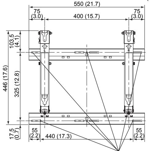
Wall mounting holes (at 6 points)
Use the screws without fail to anchor the fixture.
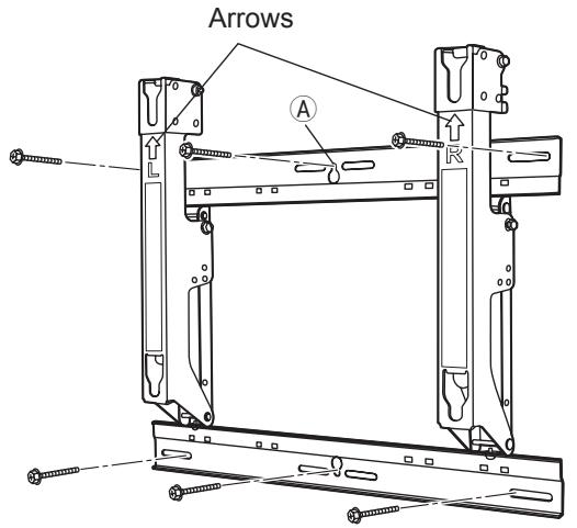
3. Installing the wall-hanging bracket on the wall
① Install the wall-hanging bracket so that the arrows indicated on it are pointing upward.
② First of all, secure the screw in the upper center hole Ⓐ.
③ Use a level to ensure that the fixture is not tilting on one side, and then secure the screws in the five remaining holes.
Notes
- If it is necessary to embed bolts or nuts in the wall prior to installing the wall-hanging bracket because the wall is made of concrete, for instance, locate the positions of the holes by putting the actual wall-hanging bracket in place on the wall or by calculating the hole positions from the outline drawing, and then embed bolts and nuts with a nominal diameter of 6 mm (0.2 inches) or their equivalent. When embedding the bolts, ensure that their heads protrude by 10 to 15 mm (0.4 to 0.6 inches) from the surface of the wall.
- For installing the wall-hanging bracket onto the wall, use screws with a nominal diameter of 6 mm (0.2 inches) or their equivalent available from a hardware store and suited to the materials of the installation area on the wall.
- Anchor the screws in at least six locations.
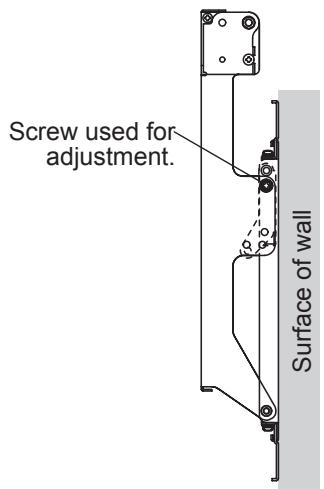
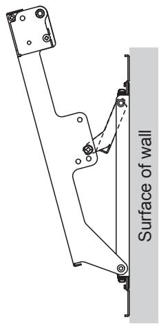
4. Adjusting the angle of the wall-hanging bracket.
① The angle of this wall-hanging bracket can be adjusted in 5-degree increments to one of five positions ranging from “zero tilting” to “20-degree tilting.”
When the wall-hanging bracket is shipped from the manufacturing plant, the angle is set to “zero tilting.” To change this angle, remove the screws used for adjustment and change the position of the stay.
(Tightening torque: 1.2 to 1.5 N•m)
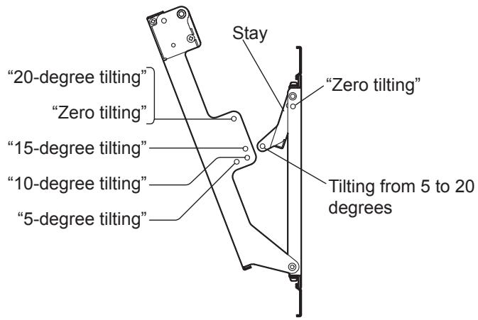
When the angle is set to"Zero tilting"
When the angle is set to"15-degree tilting"
Note
- When using some types of HDMI cables (RP-CDHG80 or RP-CDHG100) or PC cables, the cable may touch the wall and cause damage to the HDMI terminal or the PC input terminal on the television set. In such a case, adjust the angle of the wall-hanging bracket so that no weight is applied to the cable.
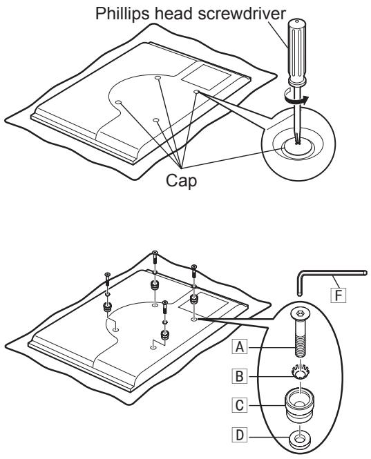
5. Installing the insulation spacers onto the plasma TV
① Place the plasma TV face down on a clean blanket or other piece of fabric free from dirt and foreign matter, and proceed as instructed below.
Take care to prevent scratches or damage if the plasma TV has protruding parts.
② Use a Phillips head screwdriver to remove the caps (4) from the plasma TV.
Note
- Keep the caps which have been removed in a safe place. (They will be required when a separate installation stand is used.)
③ As shown in the figure on the right, install the accessory M8×32 Allen head countersunk screws A, dished toothed washers B, insulation spacers C and spacers D (x4 for each part) using included allen wrench F at the locations where the caps were previously installed. (Tightening torque: 3 to 4 N•m)
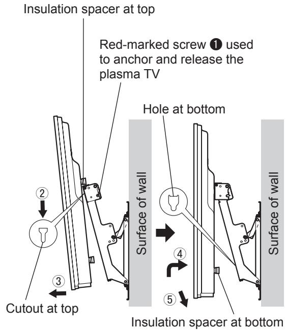
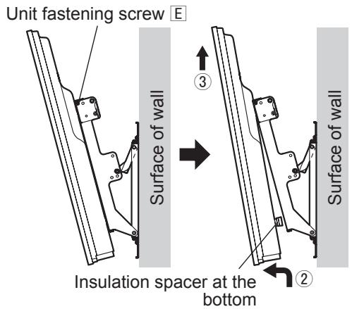
6. Mounting the plasma TV onto the wall-hanging bracket and connecting it to the other components
① Remove the left and right red-marked screws ① (one at the left and one at the right) used to anchor and release the plasma TV.
② Fit the insulation spacers at the top of the plasma TV onto the cutouts at the top of the wall-hanging bracket, and lower the plasma TV.
③ Pull the plasma TV toward you as shown in the figure on the right, and connect it to the other components.
④ After completing the connections, lift the plasma TV slightly, and insert the insulation spacers at the bottom into the holes at the lower part of the wall-hanging bracket.
⑤ Now lower the plasma TV.
CAUTION
- If the plasma TV is lifted too much, its top part will become disengaged from the wall-hanging bracket.
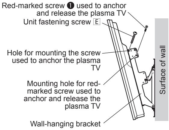
7. Anchoring the plasma TV
① Install the accessory Unit fastening screws E (2) into the screw mounting holes on the sides (left and right) of the wall-hanging bracket used to secure the plasma TV.
② Securely tighten the left and right red-marked screws ① (one at the left and one at the right) used to anchor and release the plasma TV in the red-marked screw mounting holes on the side of the wall-hanging bracket used to anchor and release the plasma TV.
(Tightening torque: 1.2 to 1.5 N·m)
Note
- In order to prevent the plasma TV from becoming disengaged from the wall-hanging bracket, the Unit fastening screws E must be securely tightened at the left and right as far as their bases.
8. How to remove the plasma TV from the wall-hanging bracket
① Remove the Unit fastening screws E (one at the left and one at the right) installed at the sides of the wall-hanging bracket.
② While lifting the bottom part of the plasma TV, pull the plasma TV toward you.
③ Once the insulation spacers at the bottom have been released, lift the plasma TV straight up.
Warnung
natural_image
Technical line drawing of a mechanical frame assembly with no visible text or symbolsnatural_image
Technical line drawing of a mechanical frame assembly (no text or symbols)4. De hoek van de muurbevestigingssteun instellen
natural_image
Technical line drawing of a mechanical linkage or bracket assembly with no visible text or symbolsOpmerking
natural_image
Line drawing of a vehicle chassis frame (no text or symbols)④ Viti M5x8 di
natural_image
Technical line drawing of a mechanical frame assembly with no visible text or symbolsnatural_image
Technical line drawing of a mechanical frame assembly with no visible text or symbolsnatural_image
Technical line drawing of a mechanical frame assembly with no visible text or symbolsA Tornillos Allen M8×32 de cabeza avellanada (4)
D Espaciadores (4)

B Arandelas dentadas convexas (4)

natural_image
Technical line drawing of a mechanical frame assembly with no visible text or symbolsnatural_image
Technical line drawing of a mechanical frame assembly with no visible text or symbolsnatural_image
Technical line drawing of a mechanical frame assembly with no visible text or symbolsnatural_image
Technical line drawing of a mechanical frame assembly with no visible text or symbols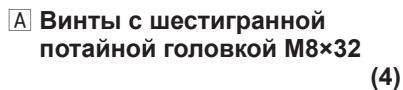


natural_image
Technical line drawing of a mechanical frame assembly with no visible text or symbolsnatural_image
Technical line drawing of a mechanical frame assembly with no visible text or symbolsYÊU CẦU LẮP ĐẶT MỘT CÁCH CHUYÊN NGHIỆP.
PANASONIC TỪ CHỐI MỘI TRÁCH NHIỂM VỀ TỔN HÀI VẬT CHẤT VÀ/HOẠC THƯƠNG TÍCH NGHIỂM TRỌNG DẮN ĐẾN CÁI CHẾT DO L{{{P}}} Đ{{{A}}} T {{K}}} H{{{O}}} G {{U}} N {{C}} A {{H}} O {{A}} C {{D}} I {{E}} U {{K}}} H{{{I}}} E {{N}} S{AI}.
natural_image
Technical line drawing of a mechanical component with no visible text or symbolsnatural_image
Technical line drawing of a mechanical component with no visible text or symbolsnatural_image
Technical line drawing of a mechanical frame assembly with no visible text or symbols(Unit : mm (inches))
(Einheit: mm)
(Eenheid: mm)
(Unità: mm)
(Unité : mm)
(Unidad: mm)
(Unidade : mm)
(Enhet: mm)
(Enhed: mm)
(Единицы: мм)
(Unit : mm (inches))
(Einheit: mm)
(Eenheid: mm)
(Unità: mm)
(Unité : mm)
(Unidad: mm)
(Unidade : mm)
(Enhet: mm)
(Enhed: mm)
(Единицы: мм)