
TY-ST65VX100 - Plasma TV mount PANASONIC - Free user manual and instructions
Find the device manual for free TY-ST65VX100 PANASONIC in PDF.
| Product Type | Plasma TV Stand |
| Brand | Panasonic |
| Model | TY-ST65VX100 |
| Compatibility | Specific Panasonic plasma screens |
| Material | Metal and plastic |
| Dimensions (pedestal) | Not specified in the manual |
| Pedestal weight | Not specified in the manual |
| Maximum supported load | Not specified, refer to screen weight |
| Main functions | Floor stand, light blocking panel, cable ties |
| Included accessories | Base, uprights, dowels, screws, fixing clips, light blocking panel, fasteners |
| Maintenance and cleaning | Soft dry cloth; mild detergent if very dirty; avoid solvents, thinners, wax |
| Safety | Professional installation required; anti-tip supports recommended; do not step on the pedestal |
| Installation | Requires at least 3 people; stable and level surface; free space of 10 cm on sides and top, 7 cm behind |
| Maximum ambient temperature | 40 °C |
| Spare parts and repairability | Contact dealer for damaged parts; do not disassemble or modify |
| General information | Manual available in several languages; free download |
Frequently Asked Questions - TY-ST65VX100 PANASONIC
User questions about TY-ST65VX100 PANASONIC
0 question about this device. Answer the ones you know or ask your own.
Ask a new question about this device
Download the instructions for your Plasma TV mount in PDF format for free! Find your manual TY-ST65VX100 - PANASONIC and take your electronic device back in hand. On this page are published all the documents necessary for the use of your device. TY-ST65VX100 by PANASONIC.
USER MANUAL TY-ST65VX100 PANASONIC
natural_image
Line drawing of a flatboard with two vertical posts and a curved base (no text or symbols)Model No.
TY-ST65VX100
| Installation InstructionsPedestal for Plasma DisplayBefore commencing work, carefully read these Instructions and the Manual for the plasma display to ensure that fitting is performed correctly. (Please keep these instructions. You may need them when maintaining or moving.) | English |
| InstallationsanleitungSockel für PlasmadisplayVor der Ausführung lesen Sie bitte diese Anleitung und die Bedienungsanleitung für das Plasmadisplay sorgfältig durch, damit die Anbringung richtig ausgeführt wird.(Bitte bewahren Sie diese Anleitung auf. Sie kann bei der Wartung oder der erneuten Anbringung der Halterung benötigt werden.) | Deutsch |
| InstallatiehandleidingVloerstandaard voor plasmaschermLees deze installatiehandleiding en de bedieningshandleiding voor het plasmascherm zorgvuldig door voordat u begint, zodat de montagewerkzaamheden op de juiste wijze worden uitgevoerd.(Bewaar deze handleiding. U hebt de handleiding weer nodig bij verwijdering of verplaatsing.) | Nederlands |
| Istruzioni per l’installazionePiedistallo per lo schermo al plasmaPrima di iniziare il montaggio leggere attentamente queste istruzioni ed il manuale dello schermo al plasma per poter procedere al montaggio in modo corretto.(Conservare poi queste istruzioni che si renderanno necessarie per la manutenzione e l’eventuale spostamento della staffa.) | Italiano |
| Instructions d’installationPiédestal pour l’écran plasmaAvant de commencer le travail, lisez attentivement ces instructions ainsi que le mode d’emploi de l’écran plasma de manière à réaliser un montage convenable.(Conservez soigneusement les présentes instructions. Vous pouvez en avoir besoin pour effectuer un entretien ou si vous désirez déplacer le piédestal.) | Français |
| Instrucciones de instalaciónPedestal para pantalla de plasmaAntes de empezar el trabajo, lea atentamente estas instrucciones y el manual de la pantalla de plasma para asegurar una instalación correcta.(Guarde estas instrucciones. Podrá necesitarlas cuando haga trabajos de mantenimiento o mueva el soporte.) | Español |
| MonteringsanvisningarBottenplatta för plasmaskärmInnan arbetet påbörjas ska du noga läsa dessa anvisningar och bruksanvisningen som medföljer plasmaskärmen för att försäkra att arbetet utförs på rätt sätt.(Bevara dessa anvisningar. Du kan behöva anlita dem på nytt för underhåll eller flyttning av hållaren.) | Svenska |
| MonteringsvejledningSokkel til plasmaskärmFør arbejdet påbegyndes, skal De omhyggeligt læse disse instruktioner og betjeningsvejledningen til plasmaskäermen for at sikre at opsætningsarbejdet udföres korrekt.(Gen disse instruktioner. De kan få brug for dem ved vedligeholdelse, eller hvis ophænget skal flyttes.) | Dansk |
| Инструкция по установкеПодставка для плазменного дисплеяПеред проведением работ внимательно прочитайте эту Инструкцию и Руководство для плазменного дисплея, чтобы убедиться в том, что установка выполняется правильно.(Сохраните, пожалуйста, эту инструкцию. Она может Вам понадобиться для технического обслуживания или перемещения.) | Русский |
| Інструкції з встановленняПідставка для плазмового дисплеяПеред початком робіт уважно прочитайте ці інструкції та інструкції з експлуатації плазмового дисплея, аби забезпечити правильний монтаж.(Збережіть ці інструкції, оскільки вони можуть знадобитись Вам, коли виникне необхідність у технічному обслуговуванні або встановленні в іншому місці.) | Українська |
■ WARNING
Do not install in a location that cannot support the entire load.
- If the pedestal is not installed correctly, the Plasma Display may fall over and become damaged, and personal injury may result.
Do not disassemble or modify the pedestal.
- Otherwise the unit may fall over and become damaged, and personal injury may result.
■ CAUTION
Do not use any display other than those given in the catalogue.
- If this is not done, the unit may fall over and become damaged, and personal injury may result.
Do not climb up onto the pedestal or use it as a step. (Young children should be made particularly aware of this caution.)
- If the unit falls over or becomes damaged through misuse, injury may result.
Do not use the pedestal if it becomes warped or physically damaged.
- If you use the pedestal whilst it is physically damaged, personal injury may result.
Set up on a stable, level surface.
- If this is not done, the unit may fall over and become damaged, and personal injury may result.
Keep the unit away from direct sunlight and heating equipment.
- Failure to do so may result in warping, deformation, or degradation of materials, and a loss of strength that may cause the equipment to fall over or break and cause injury.
During setting-up, make sure that all screws are securely tightened.
- If sufficient care is not taken to ensure screws are properly tightened during assembly, the pedestal will not be strong enough to support the Plasma Display, and it might fall over and become damaged, and personal injury may result.
Use the accessory parts for fall-prevention to secure the Plasma Display.
- If the unit is knocked or children climb onto the pedestal with the Plasma Display installed, the Plasma Display may fall over and personal injury may result.
When installing or removing the plasma display and pedestal, ensure that the work is done by at least three persons.
- If more than three people are not present, the display may be dropped, and personal injury may result.
Leave a space of at atleast 10 cm (3.9 inches) at the top, left and right, and at least 7 cm (2.8 inches) at the rear, and keep the space between the bottom of the display and the floor surface.
- Do not cover the air inlet holes and air outlet holes, or a fire may result.
■ Notes on handling
1) If the unit is placed in direct sunlight or next to a stove, the light and heat may cause discoloration or deformation.
2) Cleaning
Wipe the surfaces with a soft, dry cloth. If the unit is particularly dirty, clean it using a cloth soaked with water to which a small amount of neutral detergent has been added, and then wipe with a dry cloth.
Do not use products such as solvents, thinner or household wax for cleaning, as they can damage the surface coating.
(If using a chemically-treated cloth, follow the instructions supplied with the cloth.)
3) Do not attach sticky tape or labels, as they can make the surface of the pedestal dirty.
■ Notes on installing the pedestal
- Insert the mains plug into a mains socket which is close and easily accessible for the plasma display.
- Provide adequate ventilation so that the temperature around the display does not rise above 40^ (104 °F). If there is insufficient movement of the air inside the display, heat may build up inside the display and fire may result.
PROFESSIONAL INSTALLATION IS REQUIRED.
PANASONIC DISCLAIMS ANY PROPERTY DAMAGE AND/OR SERIOUS INJURY, INCLUDING DEATH RESULTING FROM IMPROPER INSTALLATION OR INCORRECT HANDLING.
Parts for assembly (Be sure to check the parts before assembling)
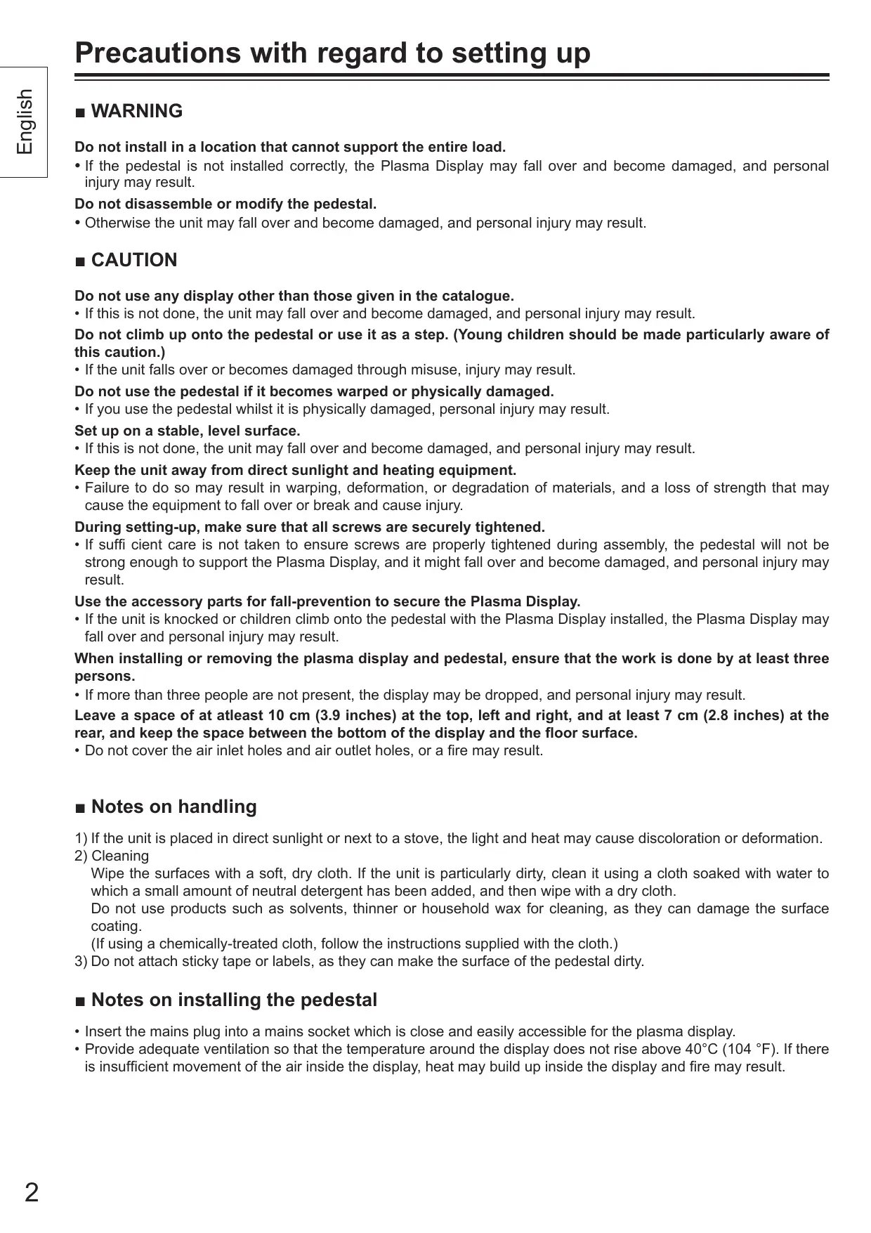
A Stand pin fixing screws (2)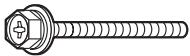 M8 × 60 M8 × 60 | E Clampers (2)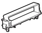 | G Stand base (1) |
| B Stand pole fixing screws (2)Stand pole display fixing screws (4)[IMAGE]M8 × 30 | F Stand poles (2)[YBAH] | |
C Fixing pins (4) | H Light-blocking panel (1)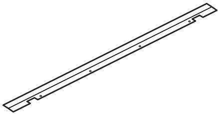 | |
D Stand pins (2)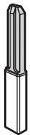 |
Assembling the pedestal
1 Place the stand base so that it is flat.
To prevent damage to the stand base, place it on a flat floor or on a stand.
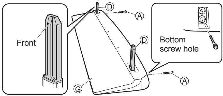
2 Attach and secure the stand pins.
(1) Insert the two stand pins Ⓓ into the top of the stand base Ⓖ.
- The stand pins Ⓓ have a front and back.
(2) Firmly secure the stand pin fixing screws Ⓐ into bottom screw hole of the stand base Ⓖ.
Attaching the pedestal to the display
For setting up the pedestal, refer to the operating instructions of plasma display.
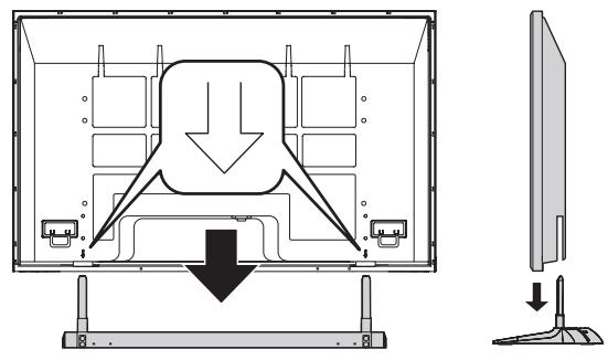
1 Attach the plasma display to the pedestal.
Arrow marks are displayed on the back cover at the locations shown below.
Align the stand pins Ⓓ with these arrows, and install the plasma display.
natural_image
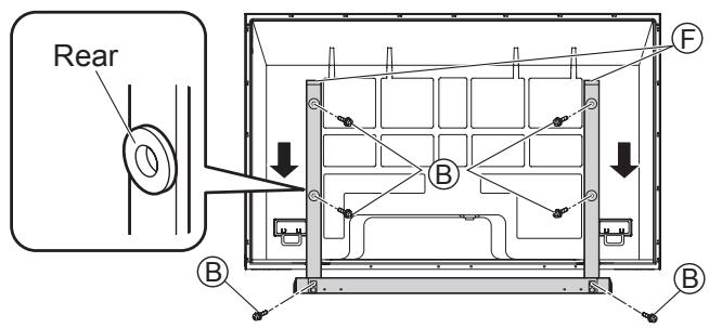
Diagram of a computer monitor showing internal components and a side-view view (no text or symbols)2 Attach the stand poles.
(1) Insert the two stand poles Ⓕ into the stand base Ⓖ from the rear of the plasma display, and then use the stand pole fixing screws Ⓑ to secure the stand poles Ⓕ.
- The stand poles (F) have a front and back.
(2) Use the four stand pole display fixing screws Ⓑ to secure the stand poles Ⓕ and plasma display.
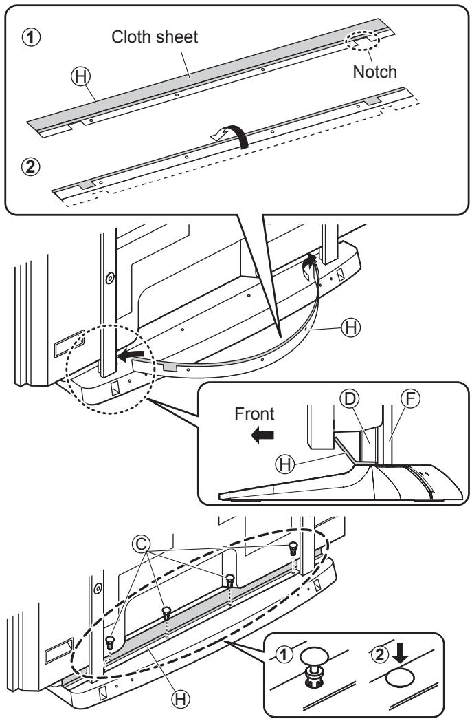
Attaching the light-blocking panel
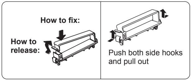
1 Prepare the light-blocking panel.
(1) Place the light-blocking panel Ⓗ with the cloth sheet facing upward.
(2) Fold over the portion of the panel with notches and holes in it along the crease. (See illustration.)
2 Attach and secure the light-blocking panel.
(1) Slightly bend the light-blocking panel to form a U-shape and fit the ends into the gaps (right and left) between the stand pins and the plasma display. Align the notches in the light-blocking panel with the stand pins.
- The cloth sheet side should be facing the rear panel of the plasma display.
(2) Align the four holes in the light-blocking panel Ⓗ with the holes in the stand base, insert the (four) fixing pins Ⓒ, and push down hard on the tops of the fixing pins to lock them in place.
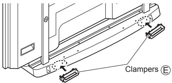
Cable binding instructions
1 Attach the clampers to the pedestal.
Attach the stand clampers Ⓔ (right and left).
2 Connect the cable and mains lead.
3 Use the clampers to bind the cable and mains lead.
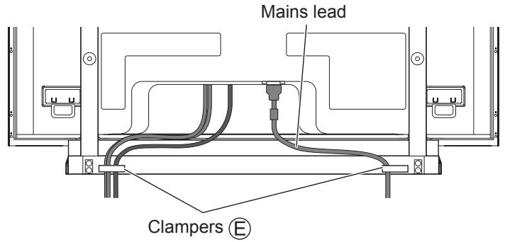
* For cable connection, refer to the operating instructions of plasma display.
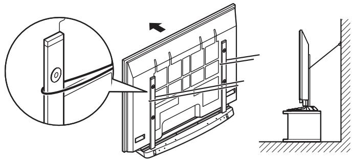
Preventing the plasma display from failing over
Accessories for pedestal security
We recommend that measures are taken to prevent the Plasma display from falling over in such an event.
* The information in this section is designed to reduce the risk of injuries caused by the Plasma display falling over during an earthquake, etc.
However, no measure can guarantee protection against all earthquakes.
Securing to a wall.
Notes:
- Securely attach to a wall, pillar or similarly solid structural feature using separately- obtained products such as cords or chains of adequate strength.
- Secure in the wall at two locations each on the left and right.
natural_image
Technical line drawing of a door frame assembly with an inset showing a close-up of the door panel (no text or symbols present)■WARNUNG
natural_image
Diagram of a computer monitor with an arrow indicating a downward motion, shown from front and side views (no text or symbols present)natural_image
Technical line drawing of a door frame assembly with an inset showing a close-up of the component (no text or symbols present)■ WAARSCHUWING
natural_image
Diagram of a computer monitor showing internal components and a separate screen with a downward arrow indicating motion (no text or symbols present)natural_image
Technical illustration of a door panel assembly with an inset showing the close-up of the component (no text or symbols present)■ AVVERTENZA
natural_image
Diagram of a computer monitor with an open panel showing internal components and a downward arrow indicating a loading or disassembly process (no text or symbols present)natural_image
Technical line drawing of a door panel assembly with an inset showing a close-up view of the component (no text or symbols present)■ AVERTISSEMENT
natural_image
Diagram of a monitor front view showing internal components and a downward arrow indicating compression or disassembly (no text or symbols present)natural_image
Technical line drawing of a door panel assembly with an inset showing a close-up view of the component (no text or symbols present)■ ADVERTENCIA
natural_image
Diagram of a monitor with an open panel showing internal components and a downward arrow indicating compression or disassembly (no text or symbols present)natural_image
Technical line drawing of a door frame assembly with an inset showing a close-up of the door panel (no text or symbols present)■ WARNING
natural_image
Diagram of a monitor with internal components and a downward arrow indicating motion, shown from front and side views (no text or symbols)natural_image
Technical line drawing of a door frame assembly with an inset showing a close-up of the door panel (no text or symbols present)■ ADVARSEL
natural_image
Diagram of a monitor with internal components and a downward arrow indicating compression or disassembly (no text or symbols present)natural_image
Technical line drawing of a door frame assembly with an inset showing a close-up of the door panel (no text or symbols present)■ ПРЕДУПРЕЖДЕНИЕ
natural_image
Diagram of a monitor front view showing internal components and a side-view view of the screen (no text or symbols present)2 Закрепите стойки.
natural_image
Technical line drawing of a door panel assembly with an inset showing a close-up detail (no text or symbols)■ ПОПЕРЕДЖЕННЯ
natural_image
Diagram of a computer monitor with an arrow indicating downward motion, showing internal components and a separate side view (no text or symbols present)natural_image
Technical line drawing of a door frame assembly with an inset showing a close-up of the door panel (no text or symbols present)Dimension diagram / Abmessungen / Afmetingen / Diagramma delle dimensioni / Dimensions / Diagrama de dimensiones / Måttdiagram / Dimensioner / Диаграмма размеров / Розміри
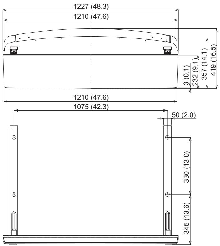
Units : mm (inches)
Einheit : mm
Eenheid : mm
Unità : mm
Unité : mm
Unidades : mm
Enhet : mm
Enhed : mm
Единицы : мм
Одиниці : мм

other
| Dimension | Value | | --------- | ----- | | Total Length | 278 (10.9) | | Total Width | 15 (0.6) | | Height | 141 (5.6) | | Total Height | 832 (32.8) | | Total Width | 255 (10.0) | | Total Height | 62 (2.4) | | Total Width | 112 (4.4) | | Total Height | 223 (8.8) |Memo :
- TY-ST65VX100
- ■ WARNING
- ■ CAUTION
- ■ Notes on handling
- ■ Notes on installing the pedestal
- Parts for assembly (Be sure to check the parts before assembling)
- Assembling the pedestal
- Place the stand base so that it is flat.
- Attach and secure the stand pins.
- Attaching the pedestal to the display
- Attach the plasma display to the pedestal.
- Attach the stand poles.
- Attaching the light-blocking panel
- Prepare the light-blocking panel.
- Attach and secure the light-blocking panel.
- Cable binding instructions
- Preventing the plasma display from failing over
- Accessories for pedestal security
- Securing to a wall.
- Notes:
- ■WARNUNG
- ■ WAARSCHUWING
- ■ AVVERTENZA
- ■ AVERTISSEMENT
- ■ ADVERTENCIA
- ■ ADVARSEL
- ■ ПРЕДУПРЕЖДЕНИЕ
- Закрепите стойки.
- ■ ПОПЕРЕДЖЕННЯ
- Dimension diagram / Abmessungen / Afmetingen / Diagramma delle dimensioni / Dimensions / Diagrama de dimensiones / Måttdiagram / Dimensioner / Диаграмма размеров / Розміри
- Memo :
Brand : PANASONIC
Model : TY-ST65VX100
Category : Plasma TV mount