805-894 - Toy Nordic Play - Free user manual and instructions
Find the device manual for free 805-894 Nordic Play in PDF.

| Product Type | Toy |
| Brand | Nordic Play |
| Model | 805-894 |
| Recommended Age | 3+ years |
| Dimensions (L x W x H) | 30 x 20 x 15 cm |
| Weight | 0.5 kg |
| Material | ABS plastic, non-toxic |
| Power Source | None (manual operation) |
| Battery Requirements | Not applicable |
| Functions | Interactive play, sound effects (if applicable), moving parts |
| Assembly Required | Yes, minor assembly (screws included) |
| Color | Multi-color |
| Safety Certifications | CE, EN71 |
| Care Instructions | Wipe clean with a dry cloth. Do not immerse in water. |
| Spare Parts Availability | Contact Nordic Play customer service |
| Repairability | Limited; no user-serviceable parts inside |
| Package Includes | 1 toy, instruction manual |
| Warranty | 2 years against manufacturing defects |
Frequently Asked Questions - 805-894 Nordic Play
User questions about 805-894 Nordic Play
0 question about this device. Answer the ones you know or ask your own.
Ask a new question about this device
Download the instructions for your Toy in PDF format for free! Find your manual 805-894 - Nordic Play and take your electronic device back in hand. On this page are published all the documents necessary for the use of your device. 805-894 by Nordic Play.
USER MANUAL 805-894 Nordic Play
natural_image
White off-road vehicle with black and white tires, featuring a 'STARTNOW' badge and roof-mounted headlights (no readable text beyond branding)

Size 114,5 x 72,5 x 73 cm
Art. no. 805-894
EAN 5705858718811
Imported by / Importeret af
NSH NORDIC A/S
Virkefeltet 4
DK-8740 Braedstrup
Made in China / produceret i Kina
General safety rules for NORDIC PLAY products
Warning:
- The vehicle may not be used on roads, sidewalks, in hills or sand.
- The vehicle should only be used on flat surfaces.
- Do not overload the vehicle. Pay attention to the maximum weight limits. Typical maximum total weight is 25 - 35 kg. Please check for your specific model.
- Only adults may charge the battery.
- Children using the vehicle should always be supervised by a responsible adult.
- Do not charge the vehicle's circuit.
- Do not drive in water or other fluids.
- Stop the vehicle when it is approaching an obstacle, turn away from the obstacle and drive somewhere else.
- Please charge the battery when the vehicle starts to drive slowly, otherwise the battery's lifespan can be shortened.
- Please charge the battery fully before the battery is stored for longer periods without use. Charge the battery every three months to extend the battery's lifespan.
- Do not drive during rain.
- Battery, charger, electrical cables, outlets and other parts should periodically be checked. If damages are discovered, the vehicle may not be used until these are fixed.
- The charger should be checked for damages on cord, plug and other parts periodically. If there are damages, the charger may not be used until the damage is fixed.
- Vehicle with a battery may not be used by children under 3 years of age.
- Push/foot-to-floor vehicles without a battery can be used from 1 year of age.
- The vehicle may only be used with the recommended charger.
• The charger is not a toy. - Only clean with a damp cloth.
- Check that all parts are undamaged. If not, repair or change these.
- It is a good idea to use safety equipment, depending on the vehicle.
- Worn out batteries should be removed/changed from the vehicle.
- The battery should be removed before the vehicle is disposed of.
- Declaration of conformity: This product is in accordance with EU directive 2014/53 / EU.
Warning:
For your child's safety, pay attention to the following:
- Only adults may assemble the product.
- Small parts and plastic parts should be kept away from the child to avoid risk of suffocation.
- Children may not touch or open the battery holder.
• Adult supervision is required. - Vehicles with a battery may not be used by children under 3 years of age.
- Push/foot-to-floor vehicles without battery can be used from 1 year of age.
- Use the vehicle with caution, since driving skills are required to avoid falls or crashes that can result in injuries to the user or third party.
- Instructions on how the vehicle is used should be given to the child before use – especially for the braking system.
- May not be used in traffic. Only use the vehicle on private property.
- Only drive on flat surfaces away from other vehicles and obstacles.
General safety rules for NORDIC PLAY products
- Avoid sharp bumps and sudden changes of the surface.
- Avoid roads and surfaces with water, sand, gravel, dirt, leaves and other debris.
- Wet weather can reduce the traction, brake effect and visibility.
- Do not drive when it is dark.
- Avoid excessive speed in conjunction with downhill driving.
- Watch out for pedestrians.
- Check and tighten all screws before every drive. Do not allow two or more children to use the vehicle at once.
- Do not use the vehicle if it has damages.
-
Change damaged parts immediately.
-
Insert 220V/12V charger cable's connector to the vehicle.
- Insert actual 220V/12V charger unit to your 220V power outlet. The battery will start charging.
- Detach after 8-12 hours
IMPORTANT NOTE: When shifting (forward/backward), please make sure the vehicle is completely stopped, otherwise it will damage the gear box and motor.
Forward: 1. Press the "Forward/backward switch" to the "Forward" position.
- Press the "Foot pedal", the vehicle drives forward.
Stop: 1. The vehicle will brake automatically, when foot is lifted from the "foot-pedal".
Back Up: 1. Press the "Forward/backward switch" to the "Backward" position.
- Press the "Foot pedal", the vehicle will back up.
Loosen the screw from the back of the seat seat, take away the seat. Then connect the battery line red wire to the red terminal of the battery and finally then connect black wire to black battery terminal. Never connect wires into the uncorrect battery terminals. After the connections, please assemble the seat back to the original place and tighten the screw.
Battery replacement and fuse
The battery is equipped with a thermal fuse which blows if the motor, battery or electrical circuit is overloaded. The vehicle must then be switched off for at least 5 minutes, after which the fuse will restore itself. If the product does not work, the fuse may therefore be the problem. To avoid this, read the following points:
- Do not overload the vehicle.
- Do not pull anything behind the vehicle.
- Do not drive up steep hills.
- Do not run into motionless objects that cause the wheels to spin.
- Do not drive at extreme temperatures.
- Make sure the product does not come into contact with liquids.
- Do not touch the electrical circuit.
As the battery gets older it will start to lose some of its capacity. Depending on the conditions, it can last anywhere from 1 - 3 years. If the battery needs a replacement, follow these steps:
- Loosen the crew and remove the seat.
- Disconnect the cables from the battery terminals.
- Remove the battery cover.
- Carefully lift the battery out of the vehicle. Depending on the condition of the battery (leakage or similar), safety equipment may be required. Do not lift the battery from its wires but from the battery itself.
- Put the battery in a plastic bag and dispose it responsibly. NEVER put the battery to general waste.
- Insert the new battery into the vehicle.
- Reconnect the cables to the new battery. Red wire to red terminal (+) and black wire to black terminal (-) of the battery.
- Slide the seat into place. Tighten the screw.
To protect the environment, batteries and electrical equipment must be disposed separately from household waste. Contact the municipality for the nearest collection point.
| Problem Possible Cause Solution | ||
| Vehicle does not run Battery low on power Recharge battery. | ||
| Thermal fuse has tripped Let the vehicle cool down for 5 minutes.Do not overload the vehicle. | ||
| Battery connector or wires are loose Check that the battery connectors and wires are firmly connected. | ||
| Battery is dead Battery lasts 1-3 years. Replace battery and recycle the old battery responsibly. | ||
| Electrical system is damaged Contact your distributor please. | ||
| Motor is damaged Contact your distributor please. | ||
| Vehicle does not run very long Battery is not properly charged. Check that the battery connectors are firmly plugged into each other when recharging. Recharge battery again. | ||
| Battery is old Battery lasts 1-3 years. Replace battery and recycle the old battery responsibly. | ||
| Vehicle runs sluggishly Battery low on power Check that the battery connectors are firmly plugged into each other when recharging. Recharge battery again. | ||
| Battery is old Battery lasts 1-3 years. Replace battery and recycle the old battery responsibly. | ||
| Vehicle is overload Reduce weight on vehicle.Maximum user weight is 25 kgs. | ||
| Vehicle is being used in unsuitable conditions Use the vehicle on flat, even surfaces. | ||
| Vehicle needs a push to go forward | Poor contact of wires or connectors | Check that the battery connectors are firmly plugged into each other when recharging. Recharge battery again. |
| “Dead Spot” on motor A dead spot means the electric power is not being delivered to the terminal con nection and the vehicle needs repair.Contact your distributor please. | ||
| Difficult shifting from forward to reverse or vice-versa | Attempting to shift while the vehicle is motion | Always completely stop the vehicle before shifting. |
| Loud grinding or clicking noises coming from motor or gear box | Motor or gears are damaged Contact your distributor please. | |
| Battery will not recharge | Battery connector or adapter connector is loose | Check that the battery connectors are firmly plugged into each other when recharging. Recharge battery again. |
| Charger not plugged in | Check that the battery charger is plugged into a working wall outlet. | |
| Charger is not working | Contact your distributor please. | |
| Charger feels warm when recharging | This is normal and not a cause for concern | |
Completely read through this manual and the troubleshooting guide table before calling. If you still need help resolving the problem Contact your distributor please.
Maintenance
- Check all screws periodically and tighten as needed.
- Check the vehicle's plastic components frequently for damage.
- The mechanical parts of the vehicle can be lubricated with oil if necessary.
- Store the product indoors to protect it from the weather.
- Keep product away from hot items such as stove and the likes.
- Do not drive in rain, snow, sand and gravel as this may damage the product.
- Do not clean the product with a garden hose and do not use soap. A dry or moist cloth is enough.
If the product is not to be used for an extended period, recharge the battery and then disconnect all cables
Installation and Operating Instructions
natural_image
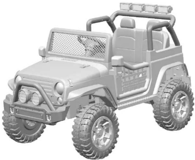
3D rendering of a toy off-road vehicle with large tires and front panel (no text or symbols visible)Please read the operating instructions carefully before use
Before using the vehicle the child should understand the vehicle controls and safety issues. They must also demonstrate the capability to handle the vehicle and operate its controls. It is the responsibility of the adult to educate the child and supervise the vehicles use. Read the following safety warnings to any child using the vehicle before riding.
| Suitable age: 3+ years Battery: 12V 10Ah | ||
| Load Capacity: 50 kg Size of car: 114,5 x 72,5 x 73 cm | ||
| Speed: 3-8 km/h | ||
| Material: Metal and plastic | Optimum temperature: | 0 - 40° |
| Charger: | Input: 100-240V AC Charging time: 8 - 12 hours | |
| Output: DC 12V 500 - 1000mA | Motor DC 12V | |
Our products are suitable for ASTM F963; GB6675,GB19865; EN71 and EN62115 standard.
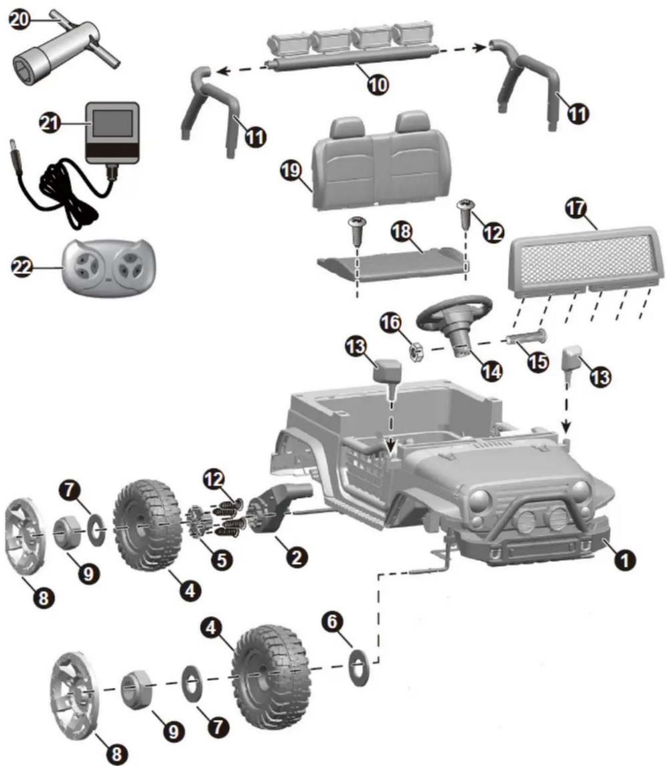
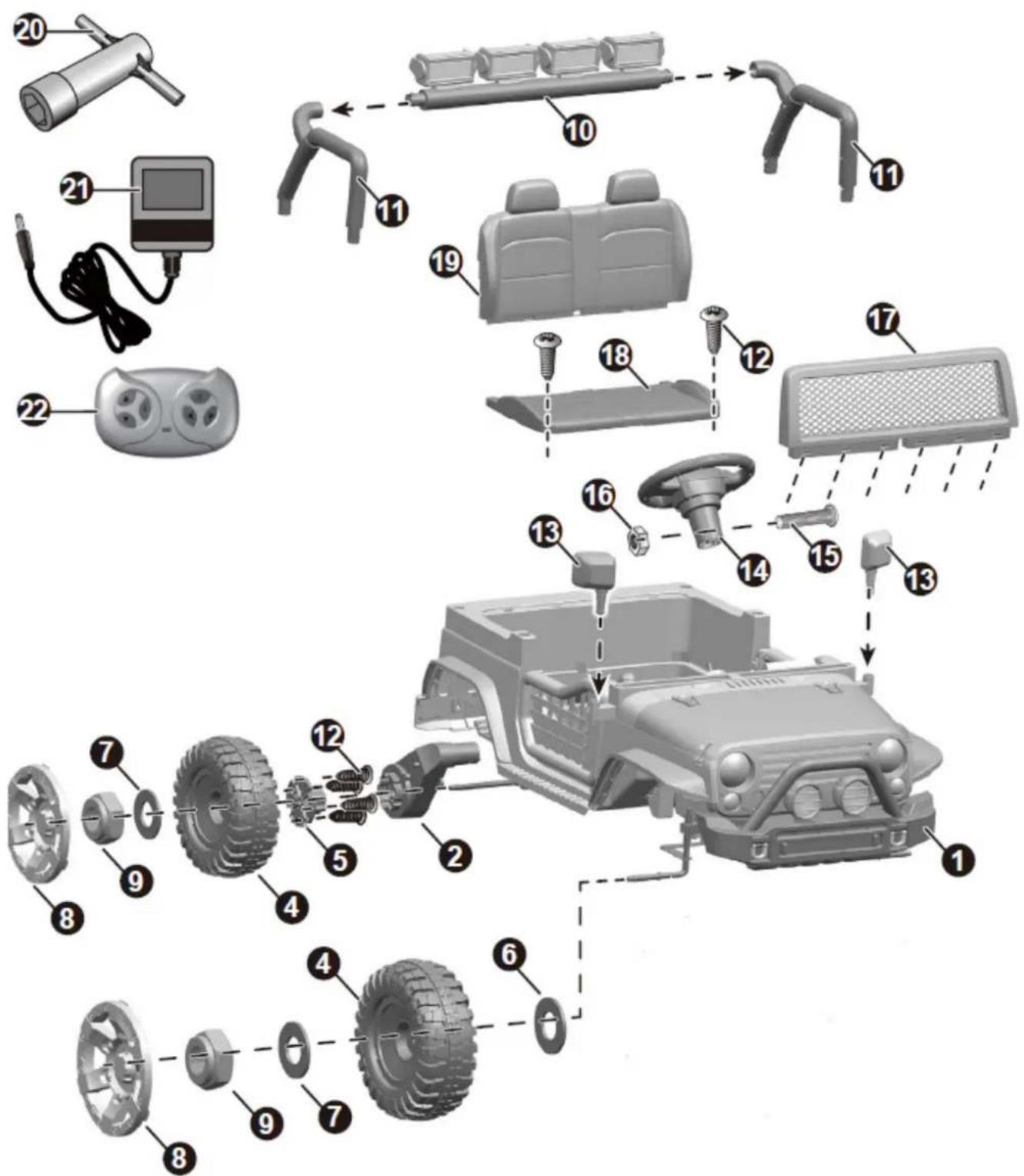
Parts list
| NO. | PART NAME | Q'TY (PCS)4WD | REMARK |
| 1 | Vehicle body 1 | ||
| 2 | Rear Gear box 2 | ||
| 3 | Front Gear box 2 | ||
| 4 | Wheel 4 | ||
| 5 | Wheel driver 4 | ||
| 6 | \ | ||
| 7 | Ø10 washer 4 | ||
| 8 | Wheel cover 4 | ||
| 9 | Lock nut | 4 | |
| 10 | Light bar linkage | 1 | |
| 11 | Light bar support | 2 | |
| 12 | Ø4 x 12 screws | 18 | |
| 13 | Side mirror | 2 | left and right |
| 14 | Steering wheel | 1 | |
| 15 | M5 x 45 machine screw | 1 | |
| 16 | Ø5 nut | 1 | |
| 17 | Windshield | 1 | |
| 18 | Seat | 1 | |
| 19 | Seat back | 1 | |
| 20 | Spanner | 1 | |
| 21 | Charger | 1 | |
| 22 | Remote controller | 1 |
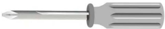
Assembly tools required (not included):
Screwdriver
natural_image
Illustration of a screwdriver with a pointed tip and threaded shaft (no text or symbols)Parts Diagram:
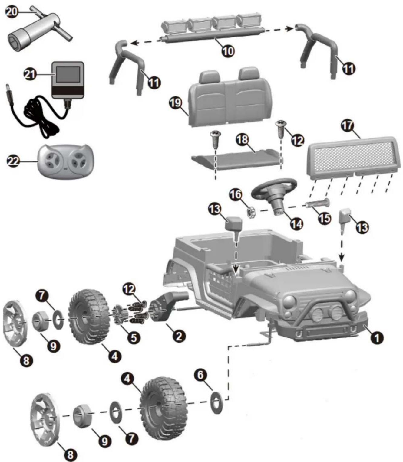
text_image
Exploded view diagram of a vehicle's internal components with numbered parts for identificationHINT: Some parts shown are assembled on both sides of vehicle
Attach the front wheels
The assembly steps on this page is for type 2WD only, if you product is type 4WD, refer to the next page please.
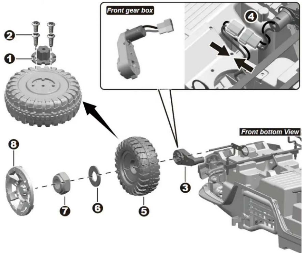
text_image
Front gear box Front bottom View1-2. Fit the wheel driver to the wheel, tighten four ∅4 x 12 screws with screwdriver.
3-4. Slide a gear box onto the front axle, and plug the connector on the gear box into the connector on the vehicle body.
5. Slide the front wheel (with wheel driver) onto the front axle and make sure the rear wheel fits with the gear box.
6. Slide the ∅10 washer onto the front axle.
7. Tighten a lock nut to the end of the front axle with a spanner.
8. Fit the wheel cover to the front wheel. Repeat for the other front wheel.
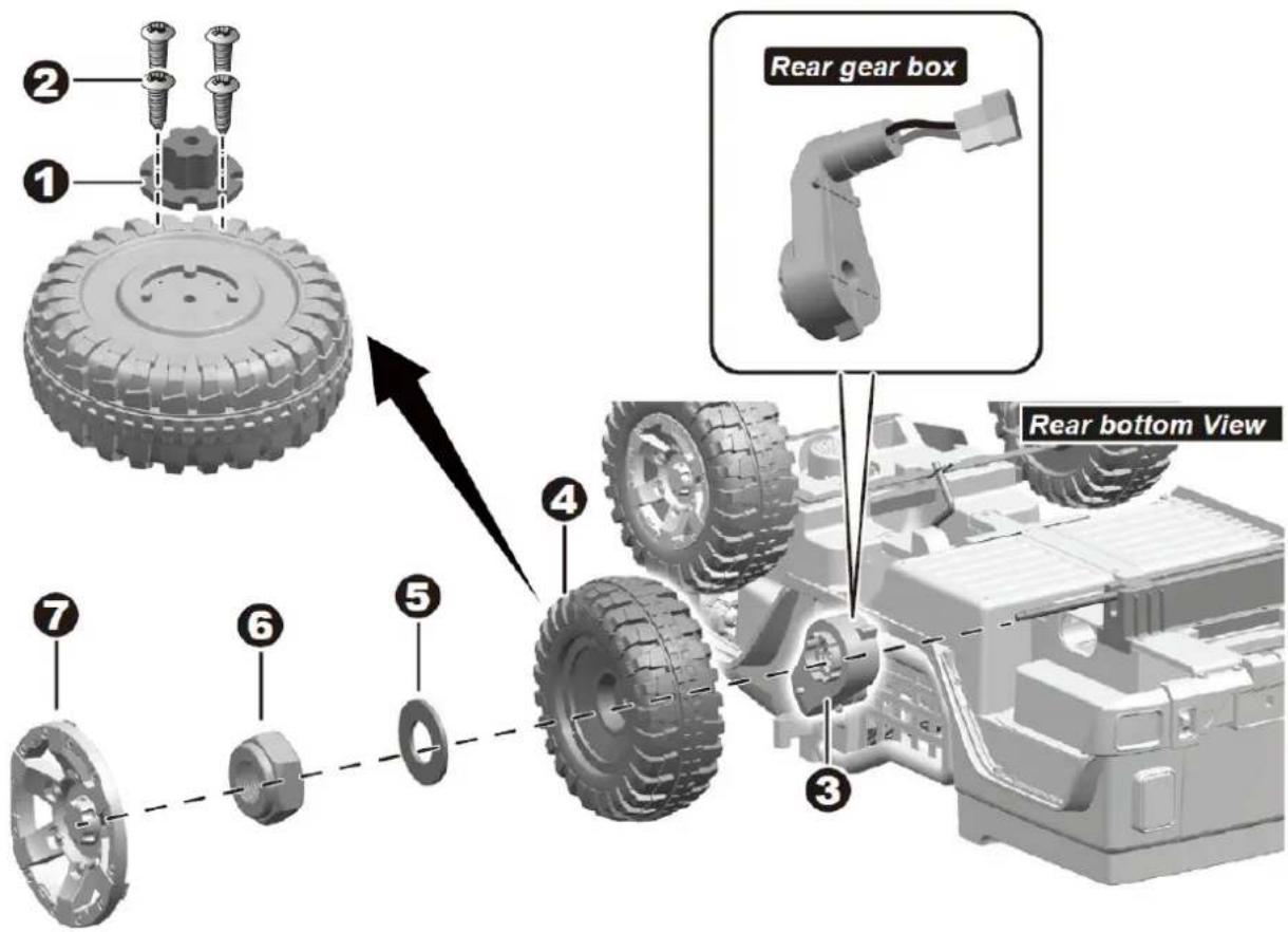
Attach the front wheels
text_image
① ② ③ ④ ⑤ ⑥ ⑦ Rear gear box Rear bottom ViewRemove all the parts from the rear axle.
1-2. Fit the wheel driver to the wheel, tighten four ∅4 x 12 screws with screwdriver.
3. Slide a gear box on the rear axle, and ensure the motor on the gear box passes through the hole in the vehicle body.
4. Slide a wheel (with wheel driver) onto the rear alxe. The gear part on the driving wheel should match up with the gear box.
5. Slide a ∅10 washer onto the front axle.
6. Tighten a lock nut to the end of the front axle with a spanner. DO NOT over tighten.
7. "Snap" the wheel cover to the wheel.
Repeat the above procedures to assemble the other rear wheel.
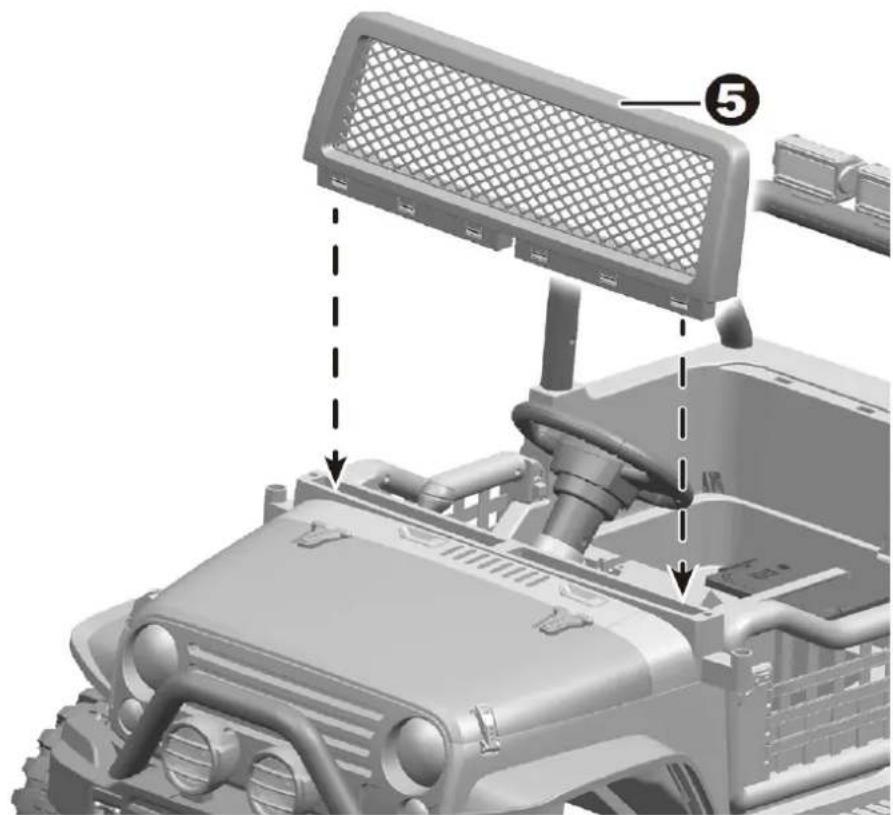
Attach the light bar
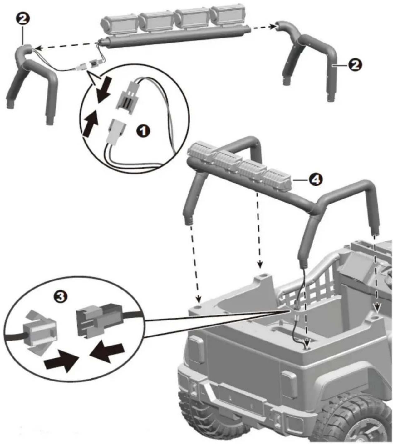
text_image
Technical diagram illustrating automotive component assembly with numbered parts and labeled connectorsTurn the vehicle body upright.
- Plug the light unit connector into the connector on the light bar support R.
- Fit the light bar supports to the light bar.
- Plug the connector on the light bar into the connector in the vehicle body.
- Insert the tabs on the light bar into the holes, and push it until you hear it "click" into placed.
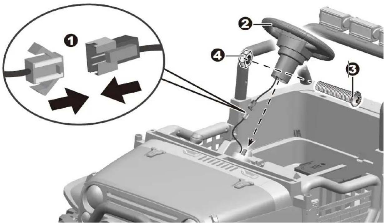
Attach the steering wheel & windshield
text_image
Technical diagram showing mechanical assembly with numbered components and directional arrows indicating assembly steps- Plug the sound unit connector on the steering wheel into the connector on the vehicle body.
- Fit the steering wheel to the end of the steering column.
- Line up the holes on the steering wheel with the holes on the steering column, insert the M5 x 45 machine screw.
- Fasten a nut on the opposite end of the screw with a screwdriver.
- Insert the tabs on the windshield into the grooves on the vehicle body, push until you hear it "click" into place.
natural_image
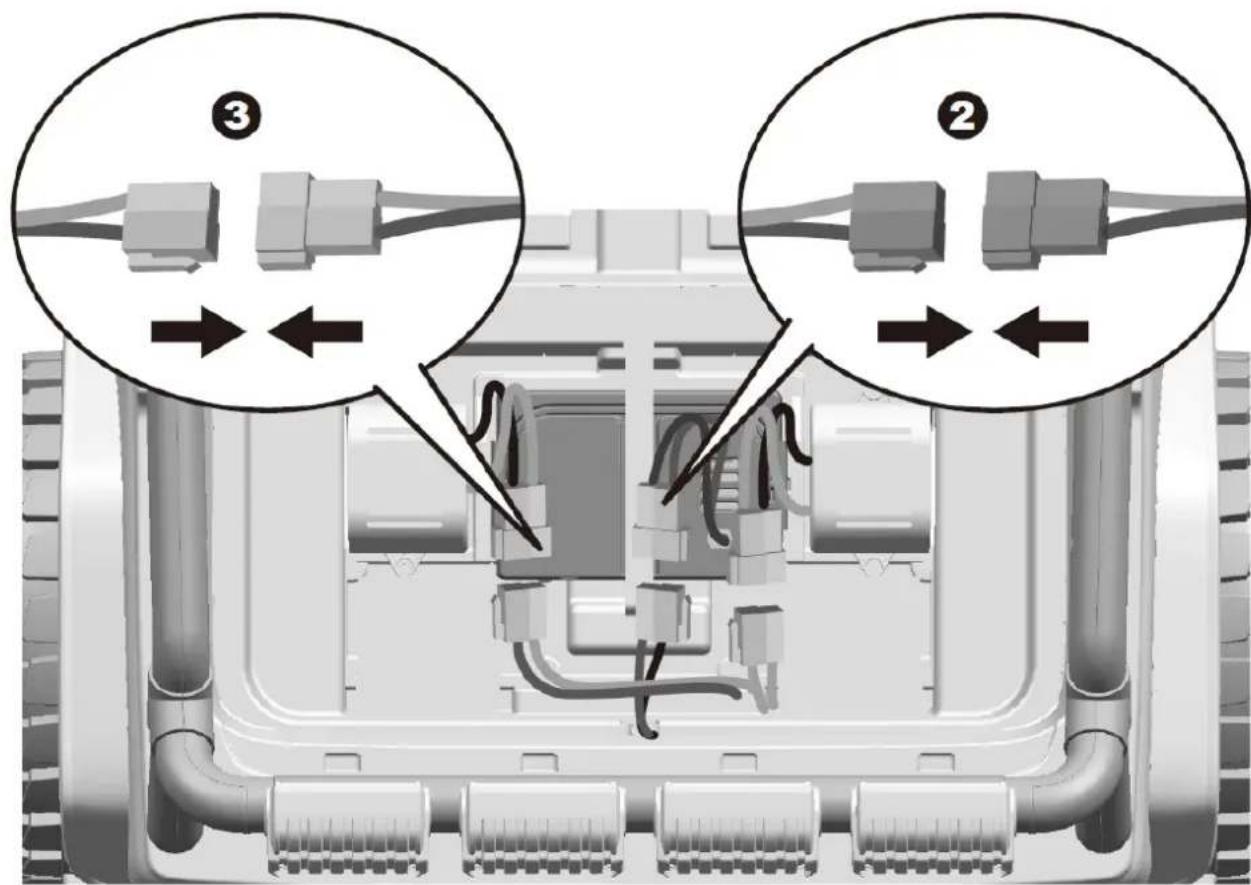
3D mechanical component diagram showing a vehicle's engine compartment with a mesh cover and labeled part (5), no readable text or symbols present.Attach the side mirrors & connect the power supply
- Insert the mirror into the hole on the side of the vehicle body.

natural_image
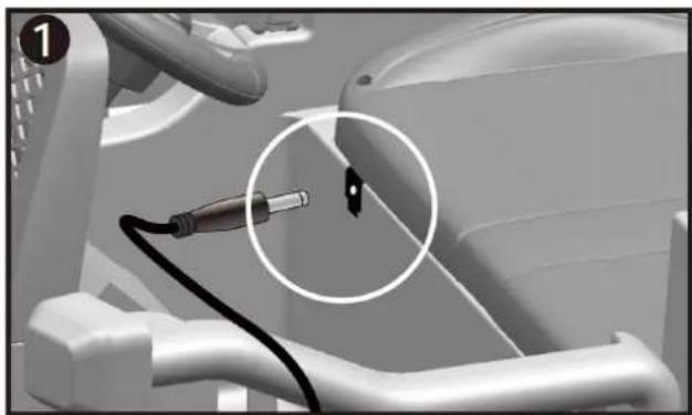
3D mechanical component diagram showing internal structure with labeled component (1), no readable text or symbols present.-
Plug the red connector on the vehicle body into the red connector on the battery.
-
Plug the white connector on the motor into the white connector of the vehicle body. Repeat for the other side.
text_image
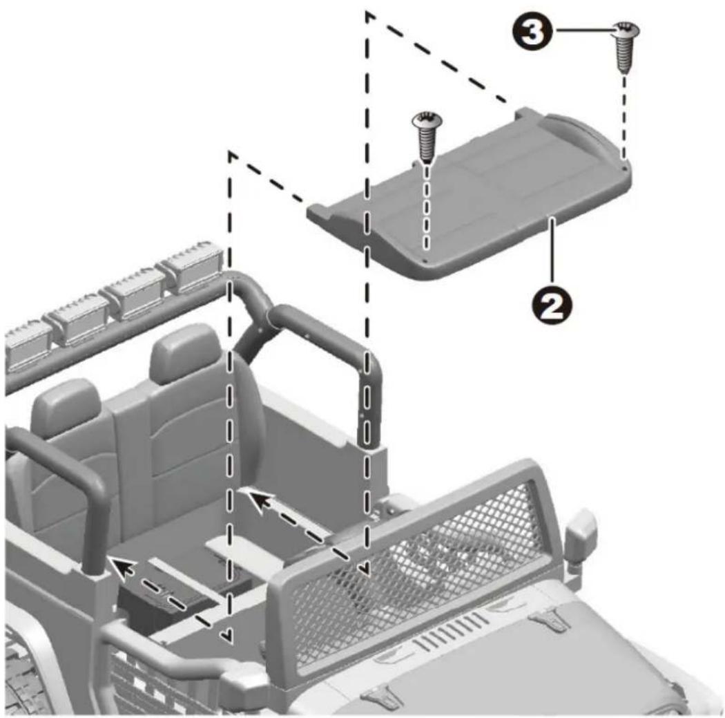
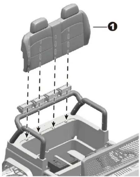
Diagram showing three labeled components (②, ③) of a mechanical or electrical component with directional arrows indicating flow or movement.Attach the seat

natural_image
3D mechanical assembly diagram showing a car interior with mounting brackets and structural elements (no text or symbols)-
Insert the tabs on seat back into the holes on the vehicle body.
-
Fit seat to the vehicle body.
-
Insert and tighten two ∅4 x 12 screws and tighten with a screwdriver.
text_image
Technical diagram showing assembly steps of a vehicle's door frame with numbered components and directional arrows indicating movement.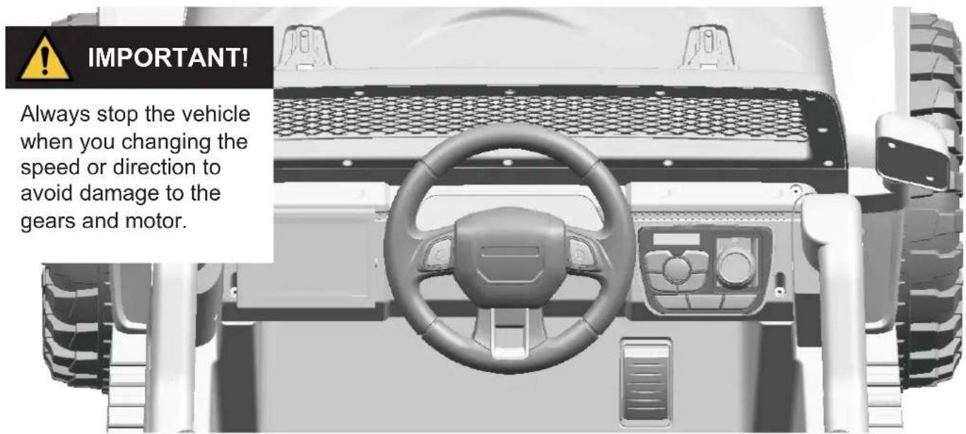
text_image
IMPORTANT! Always stop the vehicle when you changing the speed or direction to avoid damage to the gears and motor.- Foot pedal: ● To move the vehicle, press the pedal down.
-
To brake or slow down, release pressure from the pedal.
-
Horn button: Press for horn playing.
A. Power Switch: Press it to power on the vehicle, long press it for 3 seconds to power off.
B. Forward / Reverse switch:
Changes the direction that vehicle moves from forward to reverse. The vehicle equipped with 2 speeds in forward: high speed / low speed.
C. Display screen: It displays the power level of the battery when the vehicle stops. When the numerical value is less than 12, recharge the battery please.
D. Lights button: Turns the lights on and off.
E. Play / Pause
F. Previous / decrease volume
G. Next / Increase volume
H. Rocking mode
I. USB interface: Allow the audio from your portable device to be played through the vehicle speakers. MP3 format ONLY.
J. 3.5 mm AUX input: Allow the audio from your portable music player or phone to be played through the vehicle speakers. MP3 format ONLY.
K. Music mode
L. Change the audio input from the FM radio, USB, AUX input or Bluetooth
Under the FM radio mode, long press on button E (play/pause) for radio searching. When your phone is connected to the product with bluetooth, the product could answer the call through the microphone inside the dash.

text_image
C K A D L H F E G J O I B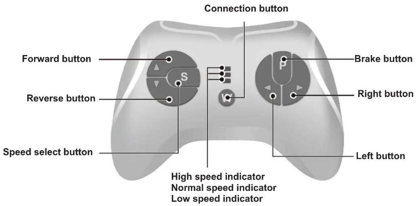
text_image
Connection button Forward button Brake button Reverse button Right button Speed select button Left button High speed indicator Normal speed indicator Low speed indicatorAttach the batteries of controller
Lift the battery compartment door on the back of the controller and insert two AAA (LR03) batteries.
HINT: Batteries not included. Refer to the Battery Information on the page 1.
1. Connection button (Build connection)
Long press on the connection buttons for 3 seconds, and the low speed indicator flashes. Then power on the vehicle, the low speed indicator goes to long bright, means the connection is successful. If the low speed indicator don't response, it means the connection failed. Replace the batteries and retry.
2. Brake button
Press the button to stop the vehicle, press it again to release the brake.
3. Speed select button
The switch operates the vehicle to move in low, normal and high speed. HINT: This switch won't work while your vehicle moves reverse.
NOTE:
- Leave the remote controller idling for about 10 seconds, it will shut down automatically.
- Rebuild connection when you replace the batteries of the remote controller.

WARNING!
ONLY AN ADULT CAN CHARGE AND RECHARGE THE BATTERY!

WARNING!
This product with Charging Protection: when charging, all functions will be cut off! Only an adult can charge and recharge the battery!
- The POWER SWITCH must be turned in OFF position when charging.
- Before the first use, you should charge the battery for 4-6 hours. Do not recharge the battery for more than 10 hours to avoid overheating the charger.
- When the vehicle begins to run slowly, recharge the battery.
• After each use or once a month minimum recharge time as 8 to 12 hours, less than 20 hours at most. - Use the only rechargeable battery and charger supplied with your vehicle.
NEVER substitute the battery or the charger with another brand. Using another battery or charger may cause a fire or explosion. - Do not use the battery or charger for any other product.
natural_image
Close-up of a car interior with a cable and connector, no visible text or symbols
natural_image
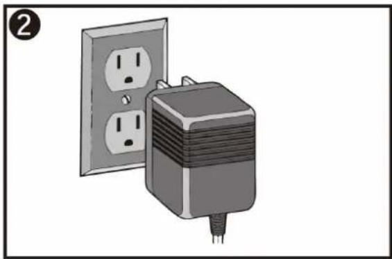
Illustration of a wall-mounted power plug next to an open socket (no text or symbols)- Plug the charger port into the input socket. (below the seat)
- Plug the charger plug into a wall outlet. The battery will begin charging.
natural_image
3D rendering of a toy off-road vehicle with large tires and front panel (no text or symbols visible)natural_image
Illustration of a screwdriver with a pointed tip and threaded shaft (no text or symbols)Del Diagram:

text_image
Exploded view diagram of a vehicle's internal components with numbered parts for identificationtext_image
Front gear box Front bottom Viewtext_image
① ② ③ ④ ⑤ ⑥ ⑦ Rear gear box Rear bottom Viewtext_image
Technical diagram illustrating vehicle assembly and component installation steps, with numbered annotations for each step.Vend bilen om på hjulene.
text_image
Technical diagram showing engine component assembly with numbered parts and directional arrows indicating assembly stepsnatural_image
3D mechanical component diagram showing a vehicle's engine compartment with a mesh cover and labeled parts (no text or symbols beyond annotations)Montering af side spejle og strømtilslutning
natural_image
3D mechanical component diagram showing internal structure with labeled component (1), no readable text or symbols present.text_image
Diagram showing three labeled components (②, ③) of a mechanical or electrical device with directional arrows indicating movement or flow.Montering af sæde
natural_image
3D mechanical assembly diagram showing a car interior with labeled parts and directional arrows (no text or symbols)text_image
Diagram illustrating vehicle gear assembly with numbered components and directional arrows indicating motion or movement.Betjening af bilen

text_image
C K A D L H F E G J O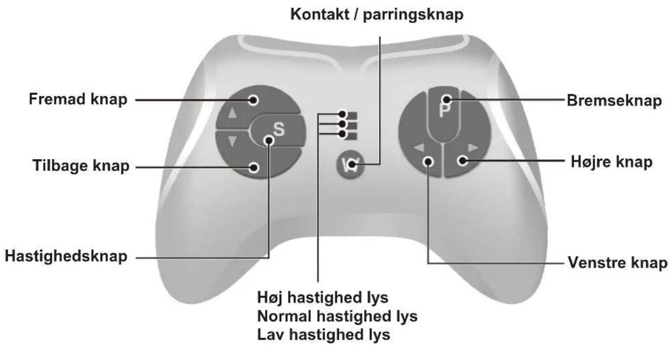
natural_image
Close-up of a car interior with a cable and connector, no visible text or symbols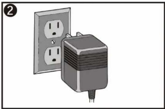
natural_image
Illustration of a wall-mounted power plug with two outlets, no text or symbols presentnatural_image
3D rendering of a toy off-road vehicle with large tires and front panel (no text or symbols visible)natural_image
Illustration of a screwdriver with a pointed tip and threaded shaft (no text or symbols)Deldiagram:
text_image
Exploded view diagram of a vehicle's internal components with numbered parts for identificationtext_image
Front gear box Front bottom Viewtext_image
① ② ③ ④ ⑤ ⑥ ⑦ Rear gear box Rear bottom Viewtext_image
Technical diagram illustrating vehicle assembly and component installation steps, with numbered annotations for each step.text_image
Technical diagram showing mechanical assembly with numbered components and directional arrows indicating assembly stepsnatural_image
3D mechanical component diagram showing engine compartment with mesh grille and labeled parts (no text or symbols beyond numbered annotations)natural_image
3D mechanical assembly diagram showing internal components with no visible text or symbolstext_image
Diagram showing three labeled components (②, ③) of a mechanical or electrical component with directional arrows indicating flow or movement.Montering av säte

natural_image
3D mechanical assembly diagram showing a car interior with mounting brackets and structural elements (no text or symbols)text_image
Technical diagram showing assembly steps of a vehicle's door frame with numbered components and directional arrows indicating movement.Användning av bilen

text_image
C K A D L H F E G J O I B
natural_image
Close-up of a car interior with a cable and connector, no visible text or symbols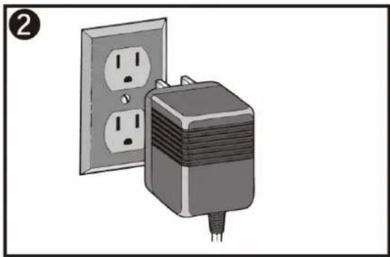
natural_image
Illustration of a wall-mounted power plug with two outlets, no text or symbols presentnatural_image
3D rendering of a toy off-road vehicle with large tires and front panel (no text or symbols visible)natural_image
Illustration of a screwdriver with a pointed tip and threaded shaft (no text or symbols)Osa kaavio:
text_image
Exploded view diagram of a vehicle's internal components with numbered parts for identificationtext_image
Front gear box Front bottom Viewtext_image
① ② ③ ④ ⑤ ⑥ ⑦ Rear gear box Rear bottom Viewtext_image
Technical diagram illustrating automotive component assembly with numbered parts and labeled connectorstext_image
Technical diagram showing mechanical assembly with numbered components and directional arrows indicating assembly stepsnatural_image
3D mechanical component diagram showing engine compartment with mesh grille and labeled parts (no text or symbols beyond numbered annotations)natural_image
3D mechanical component diagram showing internal structure with labeled component (1), no readable text or symbols present.text_image
Diagram showing three labeled components (②, ③) of a mechanical or electrical component with directional arrows indicating flow or movement.Istuimen asennus

natural_image
3D mechanical assembly diagram showing a car interior with mounting brackets and structural elements (no text or symbols)text_image
Technical diagram showing assembly steps of a vehicle's door frame with numbered components and directional arrows indicating movement.Auton käyttö

text_image
C K A D L H F E G J Onatural_image
Close-up of a car interior with a cable and connector, no visible text or symbols