
Super Silent Udtræk - Range hood Thermex - Free user manual and instructions
Find the device manual for free Super Silent Udtræk Thermex in PDF.


| Product Type | Range hood (extractor hood) |
| Brand | Thermex |
| Model | Super Silent Udtræk |
| Dimensions (W x D x H) | Approx. 600 x 500 x 300 mm |
| Weight | Approx. 8 kg |
| Power Supply | 220-240 V, 50 Hz |
| Power Consumption | Max. 200 W |
| Motor Type | Low-noise motor |
| Max. Extraction Rate | Approx. 650 m³/h |
| Noise Level (max) | Approx. 45 dB(A) |
| Number of Speeds | 3 |
| Filter Type | Aluminum grease filter, optional charcoal filter |
| Lighting | Integrated LED lights (2 x 3 W) |
| Duct Diameter | 120 mm (4.7 in) |
| Installation Type | Wall-mounted or recirculation |
| Control Type | Push buttons or slider (depending on version) |
| Energy Class | A+ (if applicable) |
| Warranty | 2 years (vary by country) |
| Maintenance | Clean grease filter monthly; replace charcoal filter every 3-6 months |
| Safety Features | Thermal overload protection, sturdy mounting brackets |
Frequently Asked Questions - Super Silent Udtræk Thermex
User questions about Super Silent Udtræk Thermex
0 question about this device. Answer the ones you know or ask your own.
Ask a new question about this device
Download the instructions for your Range hood in PDF format for free! Find your manual Super Silent Udtræk - Thermex and take your electronic device back in hand. On this page are published all the documents necessary for the use of your device. Super Silent Udtræk by Thermex.
USER MANUAL Super Silent Udtræk Thermex
natural_image
Technical diagram of a structural support frame with an arrow indicating direction (no text or symbols present)natural_image
Technical diagram of a ceiling structure with arrows indicating downward force or movement (no text or symbols present)natural_image
Technical diagram of a mechanical assembly with two components and directional arrows indicating movement (no text or symbols)Sæt recirkulationsfiltrene i emhætten.
VEDLIGEHOLD OG RENG∅RING
natural_image
Technical diagram of a mechanical assembly with arrows indicating force or movement (no text or symbols present)natural_image
Technical diagram of a mechanical assembly with two components and directional arrows indicating movement (no text or symbols)RECIRKULATIONSFILTRENE
natural_image
Technical diagram of a structural support frame with a blue arrow indicating direction (no text or symbols present)Trekk fronten på kjøkkenviften ut.
2
natural_image
Diagram of a kitchen ventilation system with blue arrows indicating airflow or movement (no text or symbols present)natural_image
Diagram of a mechanical assembly with two components and directional arrows indicating movement (no text or symbols)natural_image
Technical diagram of a ceiling-mounted fixture with two blue arrows indicating downward motion (no text or symbols present)natural_image
Technical diagram of a mechanical assembly with two blue arrows indicating direction (no text or symbols present)Sett filtrene i viften.
natural_image
Technical diagram of a structural support frame with a blue arrow indicating direction (no text or symbols present)natural_image
Diagram of a kitchen lift with two blue arrows indicating downward motion, showing structural components (no text or symbols)natural_image
Technical diagram of a mechanical assembly with two components and directional arrows indicating movement (no text or symbols)natural_image
Technical diagram of a kitchen lift with two blue arrows indicating downward motion (no text or symbols present)natural_image
Technical diagram of a mechanical assembly with two blue arrows indicating direction (no text or symbols present)RECIRKULATIONSFILTREN
natural_image
Technical diagram of a structural support frame with a blue arrow indicating direction (no text or symbols present)natural_image
Technical diagram of a kitchen fixture with two blue arrows indicating downward motion (no text or symbols present)natural_image
Technical diagram of a mechanical assembly with two components and directional arrows indicating movement (no text or symbols)natural_image
Technical diagram of a kitchen lift with two blue arrows indicating downward motion (no text or symbols present)natural_image
Technical diagram of a mechanical assembly with two blue arrows indicating direction (no text or symbols present)natural_image
Technical diagram of a structural support frame with an arrow indicating direction (no text or symbols present)Extraer la parte frontal del extractor.
2
natural_image
Diagram of a kitchen ventilation system with arrows indicating airflow or movement (no text or symbols present)natural_image
Diagram of a mechanical assembly with two components and directional arrows indicating movement (no text or symbols)natural_image
Technical diagram of a ceiling-mounted device with two blue arrows indicating downward motion (no text or symbols present)natural_image
Technical diagram of a mechanical assembly with two blue arrows indicating direction, no text or symbols present| General warning | 35 |
| Use of the hood | 36 |
| Maintenance and cleaning | 37 |
| Service | 39 |
| Environmental consideration | 39 |
GENERAL WARNING
- This hood has been developed and produced in accordance with DS/EN 60335-1.
- This hood is intended for home use only. Using for other purposes will make the warranty invalid.
- All installations must be carried out by a qualified technician in accordance with the instructions set out by Thermex Scandinavia A/S (Thermex) and the Laws in force.
- Thermex disclaims any liability for damage resulting from improper installation, assembly, operation or incorrect settings.
BEFORE INSTALLATION/OPERATION
- Check the hood for transport damage, defects and missing parts immediately upon receipt.
- Transport damage should be reported immediately to the transport company and Thermex upon receipt.
- Any defects and/or missing parts should be reported to Thermex within 8 days of receipt and prior to installation/operation.
INSTALLATION
- The hood is designed to operate at 230 volts ± 10% \~ 50 Hz in accordance with EN 50160
- Connect the hood with the attached plug. NOTE: If the plug has an Earth terminal, the hood MUST be earthed.
- For models with an external motor it is important NOT to use common zero when installing the hood and motor, as this will affect operation.
- When using an external motor from another supplier, the motor MUST be compatible with the selected hood. Failure to comply with this will invalidate the warranty.
- The hood must not be connected to the mains before installation is complete.
- The air must not be discharged from the hood into a pipe used for extraction from devices using gas or other combustible materials. Such devices must have a separate vent.
- The national law and building regulations, etc. for air emissions must be observed.
• Always use the original exhaust measurements. Reduction of the exhaust size will reduce performance and increase sound levels. - The exhaust from the hood to the outside should be as short as possible in order to maximise the efficiency of the hood.
- The number of bends on the exhaust should be minimal in order to maximise the efficiency of the hood.
- Thermex recommends that vent hoses insulated against noise and condensation for all bushings in unheated rooms are always used.
- Thermex recommends using a silencer when flexible hoses are used in order to minimise sound levels.
- When using flexible hoses, always ensure that they have been fully
extended in order to minimise air resistance and thereby maximise suction performance.
- Different materials require different rawlplugs and screws. Rawl plugs and screws suitable for the material onto which the hood will be mounted on must be used.
- If the instructions for the installation of screws and fittings are not followed, it may result in electrical shock.
- The minimum distance to gas hobs from the burner's edge to the underside of the hood MUST be a minimum of 65 cm in accordance with EN 60335-2-31.
- For cupboard-integrated, suspended and wall-mounted hoods. Thermex recommends that the distance between the hob and cooker hood is between 50 cm and 70 cm in order to ensure maximum suction.
• Always check the minimum distance between the hob and the cooker hood, as indicated in the instructions for the hob. The instructions for the hob MUST be observed if a greater distance than that recommended by Thermex is indicated in this manual. - Thermex recommends that the distance between the hob and the hood should not exceed 3 meters for ceiling-integrated models.
USE OF THE HOOD
• Always read this manual carefully BEFORE using the hood.
• Always keep this manual for future reference.
- Always disconnect the power to the hood prior to cleaning, maintenance or repair.
- Do not repair or replace any part of the hood, unless specifically recommended in the instruction manual.
• A qualified technician must carry out all repairs.
- The hood may only be used by children under 8 years of age, people with physical, mental or sensory disabilities and persons who lack experience or knowledge if these persons are supervised or have received the necessary training in the safe use of the product.
- Children should be supervised so that they do not play with the hood.
• Children may only carry out cleaning and maintenance when under supervision.
- The hood must be cleaned regularly to ensure optimal operation and long service life.
- Grease and dust debris collect in the filter and may risk igniting with insufficient cleaning.
- The hood should be cleaned inside and out frequently to avoid grease stains on walls or other surfaces.
- If the hood is used together with appliances that use gas or other combustible material, there must be adequate ventilation.
• NEVER flambé beneath the hood.
- The hood's parts may become hot during use of the hob.
USE OF THE HOOD
The hood is fitted with:
• LEDs
- Push buttons
- After-running
CONTROL PANEL
51 2 3 4
- On/off light
- Level 1
- Level 2
- Level 3
- After-running
When a function is activated, the icon for the selected function will light up.
NOTE: The front of the hood must be pulled out in order for the functions of the hood to be activated.
EXTRACTION
Activating the icon for the level the hood is to be activated on turns on the motor. If the hood is activated on level 1, the motor is turned on at speed 1. If level 2 is activated on level, the motor is turned on at speed 2. If level 3 is activated on level, the motor is turned on at speed 3.
NOTE: It can take up to 15 seconds from when a level is selected until the motor achieves the desired speed for Super Silent Extractors with an internal motor.
The hood is turned off by activating the icon for the level that the hood is operating on.
NOTE: All functions will be turned off if the hood is pushed together.
LIGHT
The light in the hood is switched on and off by activating the on/off light icon. The light can be turned on independently of whether the motor is activated.
NOTE: The light will be turned off if the hood is pushed together.
AFTER-RUNNING
If after-running is activated, the motor will run for 15 minutes at the selected speed. After-running can be activated regardless of which speed the motor is running at. Turning on the hood at the desired level activates this function, and this is followed by pressing the after-running button.
NOTE: The speed can be controlled when after-running has been enabled.
After-running can be interrupted within the 15 minutes expiration by activating the after-running icon or by switching off the hood.
RECIRCULATION
The hood can be used for recirculation. This is used in kitchens and in locations where there is no possibility of venting into the open-air. The air is first drawn through the grease filter and then through a filter with active carbon to remove odours.
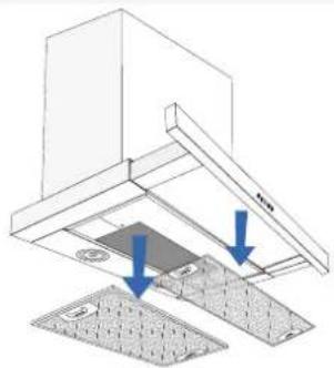
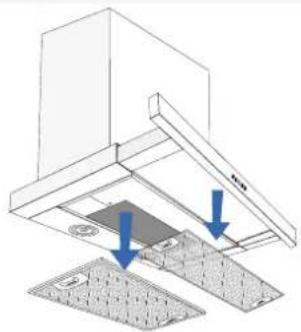
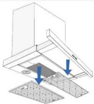
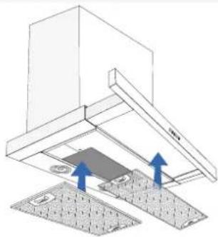
NOTE: Two recirculation filters must be used, which are installed on the motor. The recirculation filters are not included in the purchase of the hood, but can be purchased with item numbers 535.19.3750.9 and 535.19.3760.9. One of each must be used.
The recirculation filters are installed on the motor as follows:
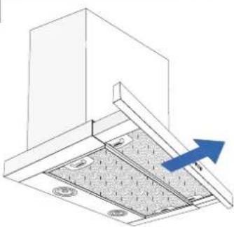
1
natural_image
Technical diagram of a structural support frame with a blue arrow indicating direction (no text or symbols present)Pull out the front of the hood.
2
natural_image
Diagram of a kitchen structure with two blue arrows indicating downward motion, showing structural components (no text or symbols)Remove the filters from the hood.
3
natural_image
Diagram of a mechanical assembly with two components and directional arrows indicating motion (no text or symbols)Replace the recirculation filters inside the hood.
MAINTENANCE AND CLEANING
• Always disconnect the power before cleaning.
- The hood must be cleaned regularly to ensure optimal operation and long service life.
- Grease and dust debris collect in the filter and may risk igniting with insufficient cleaning.
- The hood should be cleaned inside and out frequently to avoid grease stains on walls or other surfaces.
DAILY CLEANING
- For cupboard-integrated, free-hanging and wall-mounted hoods, Thermex recommends that the grease filter be wiped with a damp cloth after each cooking session. It requires very little effort every day to keep your cooker hood clean and effective.
• Steel surfaces are cleaned with a damp cloth and detergent, and finished with a metal polish (can be purchased with the item number 499.99.9999.9).
• Lacquered surfaces should be cleaned with a damp cloth with detergent/washing-up liquid. Abrasives must NEVER be used.
CLEANING THE GREASE FILTERS
Grease filters should be cleaned as needed. Thermex recommends as a minimum that the filter be cleaned at the following intervals, depending on the fat used for frying:
• Frying margarine - filter cleaned every 3 weeks
• Liquid margarine - filter cleaned every 2 weeks
- Oil - the filter must be cleaned once per week
- Deep fat frying - filter cleaned 2-3 times per week
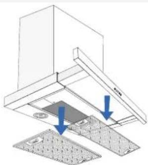
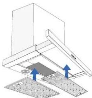
The grease filters are cleaned in the following way:
1
natural_image
Technical diagram of a kitchen fixture with two blue arrows indicating downward motion (no text or symbols present)Remove the filter from the hood.
2
- Place the filters in warm soapy water and clean if necessary with a soft brush.
- Rinse with warm water.
- Leave the filters to dry on a dishcloth or similar.
- Repeat the process if necessary.
3
natural_image
Technical diagram of a mechanical assembly with two blue arrows indicating direction (no text or symbols present)Replace the filters inside the hood.
NOTE: The filters can also be washed in the dishwasher. Please note, however, that machine washing can result in discolouration of the filters. Discolouration of the filters does not affect performance.
THE RECIRCULATION FILTERS
Be aware that recirculation filters for use without ventilation have a limited lifetime. These cannot be cleaned, and must therefore be replaced regularly.
Thermex recommends that the recirculation filters are changed a MINIMUM of twice yearly, but please note that the lifetime of a recirculation filter varies depending on the hood's use.
SERVICE
It is important that you read the installation and/or user instructions carefully before reporting your Thermex hood to the service department. This ensures that Thermex can provide you with the best possible assistance.
The service department at Thermex can be contacted regarding:
• Getting technical support for mounting and installing your hood.
- Explaining the functionalities of your hood.
• Service requests while your hood is under warranty.
Always try to disconnect the power supply to the hood for approx. 5 minutes. Reconnect the power to see if the problem has been solved.
If this does not solve the problem, disconnect the power supply to the hood for one hour. If the hood is still not working properly, even though you have consulted the troubleshooting section for help, contact the service department.
NOTE: When making inquiries regarding your warranty, you will be asked for proof of your purchase in the form of a sales receipt. You should therefore always save your sales receipt.
It is important to have all the necessary information ready before contacting us regarding service requests while your product is under warranty:
• Description of error
- Model
- Type of hood and serial number (indicated on the chassis plate)
• Purchase information
TROUBLESHOOTING OVERVIEW
| PROBLEM POSSIBLE CAUSE SOLUTION | ||
| The hood is not working | The hood is not connected to the power supply. | Check that the hood is connected to the power supply.Disconnect the power for approximately 5 minutes and connect again to check if the fault is still there. |
| Air extraction of the hood is not sufficient. | The shutter damper is blocked. | Check to see if something has fallen down onto the shutter damper or if the clamp around the shutter damper has been tightened so much that the damper cannot open.Loosen the clamp or remove the object if the shutter damper is blocked. |
| The exhaust is jammed or blocked. Check that the exhaust is not jammed or blocked. Correct if necessary. | ||
| The filters are dirty or blocked. Check to see if the filters are clean and if necessary, clean them according to the section on cleaning and maintenance in this manual. | ||
ENVIRONMENTAL CONSIDERATION
PACKAGING
The packaging must be disposed of in accordance with the local regulations for waste management.
DISPOSAL OF THE HOOD

The symbol 📄 on the product or the accompanying documentation indicates that this product must not be disposed of as household waste but delivered to the nearest collection centre for the recycling of electrical and electronic equipment.
THERMEX SCANDINAVIA A/S SERVICEAFD.
- VEDLIGEHOLD OG RENG∅RING
- RECIRKULATIONSFILTRENE
- RECIRKULATIONSFILTREN
- GENERAL WARNING
- BEFORE INSTALLATION/OPERATION
- INSTALLATION
- USE OF THE HOOD
- EXTRACTION
- LIGHT
- AFTER-RUNNING
- RECIRCULATION
- MAINTENANCE AND CLEANING
- DAILY CLEANING
- CLEANING THE GREASE FILTERS
- THE RECIRCULATION FILTERS
- SERVICE
- ENVIRONMENTAL CONSIDERATION
- THERMEX SCANDINAVIA A/S SERVICEAFD.
Brand : Thermex
Model : Super Silent Udtræk
Category : Range hood